EP1189332A2 - Motor mit integriertem Wellgetriebe - Google Patents
Motor mit integriertem Wellgetriebe Download PDFInfo
- Publication number
- EP1189332A2 EP1189332A2 EP01120391A EP01120391A EP1189332A2 EP 1189332 A2 EP1189332 A2 EP 1189332A2 EP 01120391 A EP01120391 A EP 01120391A EP 01120391 A EP01120391 A EP 01120391A EP 1189332 A2 EP1189332 A2 EP 1189332A2
- Authority
- EP
- European Patent Office
- Prior art keywords
- motor according
- toothing
- segments
- yoke
- bell
- Prior art date
- Legal status (The legal status is an assumption and is not a legal conclusion. Google has not performed a legal analysis and makes no representation as to the accuracy of the status listed.)
- Withdrawn
Links
Images


Classifications
-
- H—ELECTRICITY
- H02—GENERATION; CONVERSION OR DISTRIBUTION OF ELECTRIC POWER
- H02K—DYNAMO-ELECTRIC MACHINES
- H02K41/00—Propulsion systems in which a rigid body is moved along a path due to dynamo-electric interaction between the body and a magnetic field travelling along the path
- H02K41/06—Rolling motors, i.e. motors having the rotor axis parallel to the stator axis and following a circular path as the rotor rolls around the inside or outside of the stator ; Nutating motors, i.e. having the rotor axis parallel to the stator axis inclined with respect to the stator axis and performing a nutational movement as the rotor rolls on the stator
Definitions
- the invention relates to a motor with an integrated Harmonicdrive gearbox in the preamble of claim 1 defined genus.
- Harmonicdrive gearboxes also called wave gearboxes
- Harmonicdrive gearboxes have that The advantage of a very high reduction with a compact design.
- Such a Harmonicdrive gear becomes elastic deformable element (Flexspline) with external teeth with an internal toothing that is a few teeth larger (Cirularspline) rolled off by oval deformation.
- Harmonic Piezodrive miniaturized servo drive VDI / Z special drive technology April 99, page 15, Oliver Barth: "Harmonic Piezodrive, a miniaturizable servo drive ”
- Harmonic Piezodrive miniaturized servo drive VDI / Z special drive technology April 99, page 15, Oliver Barth: "Harmonic Piezodrive, a miniaturizable servo drive ”
- Hardspline elastic deformable element
- the motor according to the invention with an integrated harmonic drive gear has the advantage of a compact, flat design with very high output torque and extreme dynamics. There in him only the magnetic field and no large mass at high speed circulates, it is highly dynamic and generates a high Torque at low speeds.
- the engine is simple composed of a few repeating parts and light to assemble. Because of its flat design and its high
- the output torque is as a servomotor, especially in Motor vehicles, suitable for any positioning tasks. So can he e.g. as a selector motor or shift motor in automatic gearboxes with its fast ramp-up the switching times shorten considerably. When used in window regulators or He can almost see sunroofs when a jam occurs be stopped without delay.
- the outer element has a plurality of on one Output shaft coaxial dividing circle arranged equidistant Electromagnets, each electromagnet a U-shaped Yoke with two radially extending yoke legs and a connecting, axially aligned yoke web having.
- An outer toothing section is arranged on the yoke legs.
- the yoke is preferably laminated, and each is made of wedge-shaped rolled sheet metal strip has yoke a one-piece molded tooth of the internal toothing. The thickness of the slats is due to the tooth pitch Internal teeth given.
- the external teeth are arranged in bell tongues is preferably formed on a flexible ring which the free ends of the bell tongues on the outer element enclosing facing outer surface. While the bell is off a material with good magnetic properties is made, the flexible ring is made of spring steel manufactured and is therefore more wear-resistant than magnetic better materials.
- the inner element with external teeth from a variety of radially aligned segments composed by at least one spring ring displaceable in the radial direction are held, each segment preferably one integrally molded tooth of the external teeth.
- the thickness of the segments is again due to the tooth pitch the external toothing.
- the segments in at least one non-rotatably connected to the output shaft cylindrical driver held the segments in Radial slots slidably accommodates.
- two drivers on the output shaft at an axial distance arranged from each other, and in the circumferential direction successive segments, each with two axially teeth that are spaced apart from one another are rotated by 180 ° each alternately used in one and the other driver.
- the yokes of the electromagnets carry the on both pole faces Yoke leg an internal gear section one of two arranged in an axial distance from each other, ring-shaped Internal gears.
- Integrated harmonic drive gear in the following harmonic magnetic motor called, has a fixed outer element 11 with an annular internal toothing 12 in FIGS. 1-3 and in Figures 4-6 two axially spaced apart Internal gears 12, 12 'and one of the outer element 11 concentrically enclosed inner element 13 with in FIGS. 1-3 an external toothing 14 and two of them in FIGS. 4-6 axially spaced external toothings 14, 14 ', whose on the full number of teeth by at least two teeth is smaller than the number of teeth of the internal toothing 12 or 12 '.
- the division of internal and external gearing is the same.
- the inner element 13 is non-rotatably seated on a coaxial Output shaft 15 and is in the region of its ring-shaped External teeth 14, 14 'flexible, so that the External teeth 14, 14 'is oval deformable and thus with successive gear sections in the Internal teeth 12, 12 'can engage, which is Inner element 13 overall by oval deformation on the Internal toothing 12, 12 'rolls.
- the oval deformation will thereby by means of at least one rotating around the outer element 11 Magnetic field causes that in the area of the teeth 12, 14th or 12 ', 14' one on an external toothing section 141 acting, radially outward magnetic force (arrow 16 in Fig. 1).
- the outer element 11 has a plurality of electromagnets 17, the on a 15 coaxial to the output shaft dividing circle are arranged equidistant.
- the number of electromagnets 17 is preferably greater than six, but should not be too large be chosen because with it the effort for the electronics increases. A large number of electromagnets 17 lead to a more even process of passing on the External teeth 14, 14 'of the inner element 13 on the Internal teeth 12, 12 'on the outer element 11.
- everyone Electromagnet 17 has a U-shaped yoke 18 with two Yoke legs 181, 182 and one the yoke legs 181, 182 connecting yoke web 183.
- the yokes are 18 arranged so that the yoke legs 181, 182 radially are aligned and the yoke web 183 is in the axial direction extends. There is a magnetic coil 19 on each yoke web 183 arranged.
- the internal toothing 12 or 12 'of the outer element 11 is in the exemplary embodiments on eight electromagnets 17 divided, each with an internal gear section 121, 121 'is assigned to an electromagnet 17 and on the from the free ends of the yoke legs 181, 182 formed pole faces facing the inner element 13 are arranged.
- the yokes 18 are laminated wedge-shaped rolled sheet metal strip, and each Yoke plate carries one tooth of the internal toothing 12 or two Teeth of the internal toothing 12 ', which is integrally formed or which are molded in one piece.
- the yoke blades are out wedge-shaped rolled sheet metal strip, and their thickness depends on the tooth pitch of the internal toothing 12.
- harmonic magnetic motor in 1-3 are only on the lower yoke leg 181 of the Electromagnet 17 arranged internal toothing sections 121, which together form a coaxial ring gear Add tooth-free sections in between.
- the Exemplary embodiment of the harmonic magnetic motor according to FIG. 4 - 6 carry both the yoke legs 181 and Yoke leg 182 on their pole faces Internal toothing sections 121 and 121 ', each in same way to a ring gear with intermediate complete toothless sections.
- the inner element 13 is in the embodiment of the 1 - 3 as bell 20 with harmonic magnetic motor Bell bottom 201 and bell jacket 202 formed, the Bell jacket 202 from the edge of the bell to the bottom of the bell 201 is slotted, so that a variety of in Circumferential direction of adjacent flexible Bell tongues 21 results (Fig. 2).
- Bell 20 is off made of ferromagnetic material.
- the free ends of the Bell tongues 21 are on the outer element 11 facing outer surface of a flexible ring 22nd enclosed, which carries the external toothing 14.
- the flexible one Ring 22 with external teeth 14 is made of spring steel manufactured.
- the mode of operation of the Hamonic magnetic motor according to FIGS. 1-3 is as follows:
- the tooth segments 23, 24 are made of ferromagnetic material, namely from profile rolled sheet metal strips, the thickness of which by the Tooth pitch of the external toothing 14 of the inner element 13 is determined.
- the tooth angle of the teeth 25, 25 determines that removable torque on the output shaft 15.
- the segments 23, 24 are in two drivers 28, 28 ' added, which are rotationally fixed on the Output shaft 15 sit.
- Each driver 28, 28 ' has one half of the number of segments 23, 24 corresponding number of Radial slots 29 that are slightly wider than the thickness of the Segments 23, 24 are executed.
- the segments 23 are in the radial slots 29 of the driver 28 and the segments 24 inserted into the radial slots 29 of the driver 28 '. there the segments 23, 24 remain in their respective radial slots 29 radially displaceable.
- the outer element 11 carries two at the same distance as the external teeth 14, 14 ' of the inner element 13 arranged internal teeth 12, 12 ', from which the internal toothing 12 in turn Internal gear sections 121 is composed, which the pole faces of the yoke legs 181 of the electromagnets 17 are formed, and the internal toothing 12 ' Internal gear sections 121 'is composed, which the pole faces of the yoke legs 182 are formed.
- the Internal teeth 12 and 12 ' have the same number of teeth, which in the same way as in Figs. 1-3, i.e. at least by two teeth, is greater than the number of teeth also identically designed external gears 14 and 14 '.
- each driver 28, 28 ' has a cylindrical part 281 or 281 'and a flange 282 and 282', the Radial slots 29 in the cylinder part 281 or 281 ' are introduced, while the flange 282 and 282 ' Segments 23, 24 overlaps in the radial direction, so that the Segments 23, 24 essentially in the axial direction immovable between the flange parts 282 and 282 'of Carriers 28, 28 'are held.
- the invention is not based on those described Embodiment limited. So with appropriate Concession to the size of the harmonic magnetic motor according to the embodiment of FIGS. 4-6 with only one Internal and external teeth are executed. In this In this case, all segments are in a single carrier recorded and wear only one on their outer edge Tooth of the external toothing. The outer element is then as in the embodiment of FIGS. 1-3 executed, ie with provided only with an internal toothing.
Abstract
Description
- Fig. 1
- einen Halbschnitt eines Harmonic-Magnetmotors gemäß Linie I - I in Fig. 2,
- Fig. 2
- eine Ansicht des Motors in Richtung II in Fig. 1,
- Fig. 3
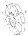
- eine perspektivische Darstellung der Ansicht des Motors gemäß Fig. 2 mit abgenommenem Außenverzahnungsring,
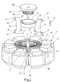
- Fig. 4
- eine perspektivische Ansicht eines Harmonic-Magnetmotors gemäß einem weiteren Ausführungsbeispiel mit einigen nach Art einer Explosionsdarstellung herausgezogenen Bauteilen,
- Fig. 5
- eine Draufsicht des Motors in Richtung Pfeil V in Fig. 4,
- Fig. 6
- einen Schnitt längs der Linie VI -VI in Fig. 5.
Claims (15)
- Motor mit integriertem Harmonicdrive-Getriebe, der ein feststehendes Außenelement (11) mit mindestens einer ringförmigen Innenverzahnung (12) und ein von dem Äußenelement (11) umschlossenes, auf einer dazu koaxialen Abtriebswelle (15) drehfest sitzendes Innenelement (13) mit mindestens einer eine gegenüber der Innenverzahnung (12) wenig kleinere Zähnezahl besitzenden Außenverzahnung (14) aufweist, das mindestens im Bereich seiner Außenverzahnung (14) flexibel ausgebildet ist und sich mit seiner Außenverzahnung (14) durch ovale Verformung auf der Innenverzahnung (12) abwälzt, dadurch gekennzeichnet, daß die ovale Verformung mittels mindestens eines am Außenelement (11) umlaufenden Magnetfelds bewirkt ist, das im Bereich der Verzahnungen (12, 14) eine nacheinander auf aufeinanderfolgende Außenverzahnungsabschnitte (141) der Außenverzahnung (14) wirkende, radial nach außen gerichtete Magnetkraft erzeugt.
- Motor nach Anspruch 1, dadurch gekennzeichnet, daß zwei diametral am Außenelement (11) angeordnete Magnetfelder vorhanden sind, die synchron umlaufen.
- Motor nach Anspruch 1 oder 2, dadurch gekennzeichnet, daß das Außenelement (11) eine Mehrzahl von auf einem zur Abtriebswelle (15) koaxialen Teilerkreis äquidistant angeordneten Elektromagneten (17) aufweist, daß jeder Elektromagnet (17) ein U-förmiges Joch (18) mit zwei radial sich erstreckenden Jochschenkeln (181, 182) und einem diese miteinander verbindenden Jochsteg (183) aufweist und daß an mindestens einer der dem Innenelement (13) zugekehrten stirnseitigen Polflächen der Jochschenkel (181, 182) ein Innenverzahnungsabschnitt (121) angeordnet ist.
- Motor nach Anspruch 3, dadurch gekennzeichnet, daß das Joch (18) lamelliert ist und jede Jochlamelle einen einstückig angeformten Zahn der Innenverzahnung (12) aufweist.
- Motor nach Anspruch 4, dadurch gekennzeichnet, daß die Jochlamellen aus keilförmig gewalztem Blechband mit einer durch die Zahnteilung der Innenverzahnung (12) bestimmten Dicke hergestellt ist.
- Motor nach einem der Ansprüche 3 - 5, dadurch gekennzeichnet, daß das Innenelement (13) Glockenform aufweist, daß der Glockenmantel (202), vorzugsweise bis zum Glockenboden (201), geschlitzt ist und daß an den freien Enden von durch die Schlitzung gebildeten Glockenzungen (21) die Außenverzahnung (11) angeordnet ist.
- Motor nach Anspruch 6, dadurch gekennzeichnet, daß das glockenförmige Innenelement (13) aus ferromagnetischem Material hergestellt ist.
- Motor nach Anspruch 6 oder 7, dadurch gekennzeichnet, daß die Außenverzahnung (14) auf einem flexiblen Ring (22) ausgebildet ist, der die freien Enden der Glockenzungen (21) auf deren dem Außenelement (11) zugekehrten Außenfläche umschließt.
- Motor nach Anspruch 8, dadurch gekennzeichnet, daß der Ring (22) aus Federstahl hergestellt ist.
- Motor nach einem der Ansprüche 3 - 5, dadurch gekennzeichnet, daß das Innenelement (13) aus einer Vielzahl von radial ausgerichteten ringartig hintereinander gereihten Segmenten (23, 24) zusammengesetzt ist, die durch mindestens einen Federring (27, 27') in Radialrichtung verschiebbar gehalten sind und daß jedes Segment (23, 24) mindestens einen vorzugsweise einstückig angeformten Zahn (25, 25') der Außenverzahnung (14, 14') aufweist.
- Motor nach Anspruch 10, dadurch gekennzeichnet, daß die Dicke der Segmente (23, 24) durch die Zahnteilung der Außenverzahnung (14, 14') festgelegt ist.
- Motor nach Anspruch 10 oder 11, dadurch gekennzeichnet, daß die Segmente (23, 24) in mindestens einem drehfest mit der Abtriebswelle (15) verbundenen zylindrischen Mitnehmer (28, 28') gehalten sind, der die Segmente (23, 24) in Radialschlitzen längsverschiebbar aufnimmt.
- Motor nach Anspruch 12, dadurch gekennzeichnet, daß die Segmente (23, 24) mindestens einen Axialschlitz (26, 26') aufweisen, in die der mindestens eine Federring (27, 27') zur Rückstellung der radial verschieblichen Segmente (23, 24) einliegt.
- Motor nach einem der Ansprüche 10 - 13, dadurch gekennzeichnet, daß die Segmente (23, 24) aus ferromagnetischem Material hergestellt sind.
- Motor nach einem der Ansprüche 10 - 14, dadurch gekennzeichnet, daß jedes Segment (23, 24) zwei axial voneinander beabstandete Zähne einer unteren und einer oberen Außenverzahnung (14, 14') trägt, daß auf der Abtriebswelle (15) zwei Mitnehmer (28, 28') drehfest sitzen, daß in Umfangsrichtung der Mitnehmer (28, 28') aufeinanderfolgende Segmente (23, 24) um jeweils 180° gedreht abwechselnd in den einen und anderen Mitnehmer (28, 28') eingesetzt sind und daß die Joche (18) der Elektromagneten (17) an den Polflächen beider Jochschenkel (181, 182) einen Innenverzahnungsabschnitt (121, 121') einer von zwei in Axialabstand voneinander angeordneten Innenverzahnungen (12, 12') trägt.
Applications Claiming Priority (2)
| Application Number | Priority Date | Filing Date | Title |
|---|---|---|---|
| DE2000142398 DE10042398A1 (de) | 2000-08-30 | 2000-08-30 | Motor mit integriertem Harmonicdrive-Getriebe |
| DE10042398 | 2000-08-30 |
Publications (2)
| Publication Number | Publication Date |
|---|---|
| EP1189332A2 true EP1189332A2 (de) | 2002-03-20 |
| EP1189332A3 EP1189332A3 (de) | 2004-01-07 |
Family
ID=7654172
Family Applications (1)
| Application Number | Title | Priority Date | Filing Date |
|---|---|---|---|
| EP01120391A Withdrawn EP1189332A3 (de) | 2000-08-30 | 2001-08-25 | Motor mit integriertem Wellgetriebe |
Country Status (2)
| Country | Link |
|---|---|
| EP (1) | EP1189332A3 (de) |
| DE (1) | DE10042398A1 (de) |
Families Citing this family (4)
| Publication number | Priority date | Publication date | Assignee | Title |
|---|---|---|---|---|
| DE10334594A1 (de) * | 2003-07-28 | 2005-02-24 | Faurecia Innenraum Systeme Gmbh | Elektromotor |
| DE102006017713A1 (de) * | 2006-04-15 | 2007-10-25 | Zf Friedrichshafen Ag | Getriebemotor |
| DE102007058605B4 (de) | 2007-12-04 | 2014-06-18 | Wittenstein Ag | Antriebseinheit für die Antriebstechnik mit hoher Leistungsdichte mit zumindest einer Übersetzungsstufe |
| DE102012104083A1 (de) * | 2012-05-09 | 2013-11-14 | Wittenstein Ag | Lager für ein Getriebe |
Citations (2)
| Publication number | Priority date | Publication date | Assignee | Title |
|---|---|---|---|---|
| US2703370A (en) * | 1952-07-02 | 1955-03-01 | Steensen Sverre Johan | Electric compressor or pump motor with rolling rotor |
| US3561006A (en) * | 1969-05-22 | 1971-02-02 | Usm Corp | Electromagnetic actuators with deflectible rotor |
-
2000
- 2000-08-30 DE DE2000142398 patent/DE10042398A1/de not_active Withdrawn
-
2001
- 2001-08-25 EP EP01120391A patent/EP1189332A3/de not_active Withdrawn
Patent Citations (2)
| Publication number | Priority date | Publication date | Assignee | Title |
|---|---|---|---|---|
| US2703370A (en) * | 1952-07-02 | 1955-03-01 | Steensen Sverre Johan | Electric compressor or pump motor with rolling rotor |
| US3561006A (en) * | 1969-05-22 | 1971-02-02 | Usm Corp | Electromagnetic actuators with deflectible rotor |
Also Published As
| Publication number | Publication date |
|---|---|
| EP1189332A3 (de) | 2004-01-07 |
| DE10042398A1 (de) | 2002-03-14 |
Similar Documents
| Publication | Publication Date | Title |
|---|---|---|
| EP1735896B1 (de) | Einsteller für einen fahrzeugsitz | |
| EP1735178B1 (de) | Antriebseinheit eines einstellers eines fahrzeugsitzes | |
| EP1735180B1 (de) | Antriebseinheit für einen fahrzeugsitz | |
| WO2005100081A2 (de) | Antriebseinheit eines einstellers eines fahrzeugsitzes | |
| EP3803153B1 (de) | Getriebe mit zugmittel | |
| EP1626202A1 (de) | Untersetzungsgetriebe und dieses verwendende Antriebseinheit | |
| DE102019117489A1 (de) | Planetenradträger eines Planetengetriebes | |
| DE19845914C2 (de) | Antriebsvorrichtung | |
| EP1675251B1 (de) | Rohrmotor für Jalousien | |
| EP1682786B1 (de) | Aktuator mit einem elektrischen stellmotor und steuerbare reibungskupplung mit einem solchen | |
| DE10137230C1 (de) | Elektrisch angetriebenes Spannungswellen-Getriebe | |
| WO2011060881A1 (de) | Spannungswellengetriebe | |
| EP3473889A1 (de) | Antriebsvorrichtung und verfahren zum betrieb einer antriebsvorrichtung | |
| EP1189332A2 (de) | Motor mit integriertem Wellgetriebe | |
| DE102008061606A1 (de) | Bremsvorrichtung und Motor mit Geschwindigkeitsreduzierungsmechanismus | |
| DE10042678A1 (de) | Vorrichtung zum Bewegen eines Körpers, insbesondere eines Fahrzeugteils und vorzugsweise eines Fahrzeugspiegels | |
| WO2019179869A1 (de) | Planetengetriebe mit einzahnigem sonnenrad mit evoloidverzahnung | |
| DE10056597A1 (de) | Schaltgetriebe für ein Fahrrad mit Elektromotor | |
| WO2001031218A1 (de) | Doppelkupplung mit einem elektromagneten | |
| DE102017114013A1 (de) | Elektrisch angetriebener Getriebemotor | |
| DE10021368B4 (de) | Mechatronischer Aktuator | |
| EP1562275A1 (de) | Motor mit Planetengetriebe | |
| DE3728868B4 (de) | Elektromotor mit relativ zueinander drehbar und axial verschiebbar gelagertem Rotor und Stator | |
| AT525577B1 (de) | Planetengetriebe | |
| EP2306047A2 (de) | Geräuschreduzierter Antrieb für Stellsysteme |
Legal Events
| Date | Code | Title | Description |
|---|---|---|---|
| PUAI | Public reference made under article 153(3) epc to a published international application that has entered the european phase |
Free format text: ORIGINAL CODE: 0009012 |
|
| AK | Designated contracting states |
Kind code of ref document: A2 Designated state(s): AT BE CH CY DE DK ES FI FR GB GR IE IT LI LU MC NL PT SE TR |
|
| AX | Request for extension of the european patent |
Free format text: AL;LT;LV;MK;RO;SI |
|
| PUAL | Search report despatched |
Free format text: ORIGINAL CODE: 0009013 |
|
| AK | Designated contracting states |
Kind code of ref document: A3 Designated state(s): AT BE CH CY DE DK ES FI FR GB GR IE IT LI LU MC NL PT SE TR |
|
| AX | Request for extension of the european patent |
Extension state: AL LT LV MK RO SI |
|
| 17P | Request for examination filed |
Effective date: 20040707 |
|
| AKX | Designation fees paid |
Designated state(s): DE ES |
|
| STAA | Information on the status of an ep patent application or granted ep patent |
Free format text: STATUS: THE APPLICATION IS DEEMED TO BE WITHDRAWN |
|
| 18D | Application deemed to be withdrawn |
Effective date: 20050311 |