BACKGROUND OF THE INVENTION
1. Field of the Invention
The present invention relates to liquid crystal
displays and, more particularly, to a technique suitable for
use in a transflective liquid crystal display provided with
a backlight and a reflection film.
2. Description of the Related Art
Substantially all mobile phones and mobile information
terminals are now provided with liquid crystal displays, and
recently, many such mobile electronic apparatuses have been
provided with transflective liquid crystal displays.
In general, a transflective liquid crystal display
includes a reflector provided on the interior or exterior of
a pair of transparent substrates for reflecting incident
light from outside and also includes a backlight at the back
side thereof. The transflective liquid crystal display can
be used as a reflective liquid crystal display and as a
transmissive liquid crystal display by switching between a
reflective mode in which solar light or an external
illumination is used as a light source and a transmissive
mode in which light from the backlight is used as a light
source.
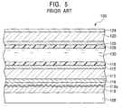
FIG. 5 is a partial sectional view of a conventional
transflective liquid crystal display. In a conventional
transflective liquid crystal display 100 shown in the
drawing, a first substrate 110 and a second substrate 120,
which are composed of a transparent material, such as glass,
are opposed to each other, and a liquid crystal layer 130 is
enclosed therebetween.
An electrode layer 115 and an alignment film 116 are
deposited in that order on a surface of the first substrate
110 facing the liquid crystal layer 130. An electrode layer
125 and an alignment film 126 are deposited in that order on
a surface of the second substrate 120 facing the liquid
crystal layer 130.
A polarizer 118 is provided on another surface of the
first substrate 110 opposite to the liquid crystal layer 130
(i.e., the outer surface of the substrate 110), and a
reflector 119 having a reflection film 119a composed of a
metal is provided on the outer surface thereof such that the
reflection film 119a faces the polarizer 118. A polarizer
128 is provided on the outer surface of the second substrate
120. A backlight 105 for transmissive display is provided
on the back of the liquid crystal display 100.
The transflective liquid crystal display 100 having the
structure described above is used, for example, as a display
area of a mobile phone. When there is sufficient external
light, the transflective liquid crystal display 100 operates
in the reflective mode in which the backlight 105 is off,
and in an environment where there is insufficient external
light, it operates in the transmissive mode in which the
backlight 105 is on.
However, in the transflective liquid crystal display
100, since the reflector 119 is placed on the exterior of
the substrate 110, light entering the liquid crystal display
100 from outside must pass through two substrates, 110 and
120, and two polarizers, 118 and 128, before being reflected
by the reflector 119. Therefore, the propagation loss of
light is increased, and it is not possible to obtain
satisfactory brightness when the transflective liquid
crystal display 100 is used as a reflective liquid crystal
display.
On the other hand, in the transmissive mode in which
the liquid crystal display 100 is used as a transmissive
liquid crystal display, although the reflector 119 must
transmit light from the backlight 105, the thickness of the
reflection film 119a is usually set at 1,000 to 1,500 Å in
order to increase the reflectance of light. That is, pores
are made in the reflection film 119a in order to transmit
light.
However, in the method in which light from the
backlight 105 is transmitted by providing the pores in the
reflection film 119a, if the aperture ratio of the pores of
the reflection film 119a is increased, the reflectance of
the reflection film 119a is decreased, thereby decreasing
brightness in the reflective mode. Therefore, it is not
possible to sufficiently increase the aperture ratio, and
satisfactorily bright display is not obtained when the
backlight 105 is lit.
In order to solve the problems described above, a
structure is disclosed, in which a reflector is placed
between two substrates constituting a liquid crystal display
so that the number of layers of substrates and polarizers
through which light passes before reaching the reflector is
decreased, and, by suppressing the propagation loss of light
in the reflective mode, brighter reflective display can be
obtained. By using such a structure, since display
brightness in the reflective mode is ensured where possible,
it is believed that brightness in the transmissive mode can
be increased by decreasing the thickness of the reflection
film for reflecting light to approximately 300 Å, but
brightness in the reflective mode is slightly sacrificed.
However, even if such a structure is used, although the
display brightness in the transmissive mode is improved, the
brightness in the reflective mode is the same as that of the
liquid crystal display 100. If the thickness of the
reflection film is increased to a certain degree by giving a
high priority to the brightness in the reflective mode, the
brightness in the transmissive mode becomes insufficient.
As described above, a transflective liquid crystal
display in which satisfactorily bright, easily visible
display is performed both in the reflective mode and in the
transmissive mode has not yet been produced.
SUMMARY OF THE INVENTION
It is an object of the present invention to provide a
transflective liquid crystal display in which a bright
display is obtained by efficiently reflecting light in the
reflective mode, and also in which bright display is
obtained by satisfactorily transmitting light in the
transmissive mode in which a backlight is lit. It is
another object of the present invention to provide a
transflector which is suitable for use in such a liquid
crystal display.
In one aspect of the present invention, a liquid
crystal display includes a pair of substrates which oppose
each other with a liquid crystal layer therebetween, and a
light source provided on the exterior of the pair of
substrates. At least an organic film, a metallic reflection
film, an overcoat film, an electrode layer, and an alignment
film are formed on the inner face of one of the substrates.
Many concaves are contiguously formed on a surface of the
organic film, the inner surface of each concave constituting
a part of a spherical surface, and the metallic reflection
film has a thickness of 80 to 500 Å.
In the construction of the present invention described
above, since many concaves are contiguously formed on the
surface of the organic film provided with the reflection
film for reflecting light entering the liquid crystal
display from outside, the inner surface of each concave
constituting a part of a spherical surface, it is possible
to greatly improve the reflection efficiency of light in
comparison to the conventional transflective liquid crystal
display. Therefore, it is possible to improve the
transmittance of the liquid crystal display by decreasing
the thickness of the metallic reflection film so that a
bright display is also obtained for the transmissive liquid
crystal display. Consequently, a bright display can be
obtained both in the reflective mode and in the transmissive
mode. Moreover, since bright display is enabled in the
reflective mode, it is not necessary to turn on the
backlight even when the liquid crystal display is used in a
slightly dark environment. Consequently, power consumption
can be reduced in an electronic apparatus provided with the
liquid crystal display of the present invention.
In the liquid crystal display, preferably, the metallic
reflection film has a thickness of 80 to 100 Å.
In such a construction, since the transmittance of the
liquid crystal display can be improved by decreasing the
thickness of the metallic reflection film, it is possible to
obtain a liquid crystal display exhibiting superior
visibility. Moreover, since the liquid crystal display of
the present invention has superior transmittance, it is
possible to decrease the amount of light of the backlight
required. Consequently, in the liquid crystal display of
the present invention, it is possible to reduce the power
consumption of the backlight which constitutes the majority
of the power consumption of an electronic apparatus provided
with the liquid crystal display of the present invention.
In the liquid crystal display, preferably, the depth of
the concaves is in the range of 0.1 to 3 µm, the inclination
angle of the inner surface of each concave is in the range
of -30 degrees to +30 degrees, and the pitch of the
adjoining concaves is in the range of 5 to 50 µm.
In such a construction, since the surface configuration
of the organic film is optimized, incident light from
outside is more efficiently reflected, and thereby brighter
display can be obtained.
In another aspect of the present invention, a
transflector includes a reflection layer, the reflection
layer including a metallic film deposited on a surface
thereof, many concaves being contiguously formed on the
surface, the inner surface of each concave constituting a
part of a spherical surface. The depth of the concaves is
in the range of 0.1 to 3 µm, the inclination angle of the
inner surface of each concave is in the range of -30 degrees
to +30 degrees, the pitch of the adjoining concaves is in
the range of 5 to 50 µm, and the thickness of the metallic
film is 80 to 500 Å.
In such a construction of the present invention, since
the surface of the reflection layer can be formed into an
optimum shape, light can be reflected more efficiently. By
decreasing the thickness of the metallic film placed on the
surface of the reflection layer to the value described above,
transmittance can be improved. Consequently, in both cases
when light is reflected and when light is transmitted, the
transflector exhibits superior characteristics.
In another aspect of the present invention, a liquid
crystal display includes the transflector described above.
In such a construction, it is possible to obtain a
liquid crystal display having superior visibility in which
bright display is obtained both in the reflective mode and
in the transmissive mode.
An embodiment of the present invention will now be
described, by way of example only, with reference to the
accompanying diagrammatic drawings, in which:
DESCRIPTION OF THE PREFERRED EMBODIMENTS
The embodiments of the present invention will be
described with reference to the drawings. However, it is to
be understood that the present invention is not limited to
the embodiments described below.
First Embodiment
FIG. 1 is a partial sectional view which schematically
shows a transflective liquid crystal display including an
edge thereof in a first embodiment of the present invention.
As shown in FIG. 1, in a transflective liquid crystal
display 1, a first substrate 10 and a second substrate 20,
for example, composed of a transparent glass, which oppose
each other with a liquid crystal layer 30 therebetween, are
integrally bonded to each other by a sealant 40 which is
annularly provided in the periphery of the two substrates 10
and 20.
At the liquid crystal layer 30 side of the first
substrate 10, an organic film 11 for corrugating a
reflection film 12, a metallic reflection film 12 for
reflecting light entering the liquid crystal display, color
filters 13 for performing color display, an overcoat film 14
for protecting the organic film 11 and the metallic
reflection film 12 as well as for planarizing the
corrugation due to the organic film 11 and the color filters
13, electrode layers 15 for driving the liquid crystal layer
30, and an alignment film 16 for controlling the alignment
of liquid crystal molecules constituting the liquid crystal
layer 30 are deposited in that order. At the liquid crystal
layer 30 side of the second substrate 20, electrode layers
25, an overcoat film 24, and an alignment film 26 are
deposited in that order.
A polarizer 18 is provided at a side of the first
substrate 10 opposite the liquid crystal layer 30 side (on
the outer surface of the first substrate 10), and a
retardation film 27 and a polarizer 28 are deposited in that
order at a side of the second substrate 20 opposite the
liquid crystal layer 30 side (on the outer surface of the
second substrate 20).
A backlight 5, which acts as a light source for
performing transmissive display in the transflective liquid
crystal display 1, is provided on the outer surface of the
polarizer 18 of the first substrate 10.
The organic film 11 corrugates the metallic reflection
film 12 formed thereon so that reflected light is
efficiently scattered. Since light entering the liquid
crystal display 1 is efficiently scattered by corrugating
the metallic reflection film 12, bright display is enabled
in the reflective mode.
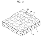
FIG. 2 is a perspective view showing a section
including the organic film 11 and the metallic reflection
film 12 formed thereon. As shown in the drawing, concaves
12A are contiguously formed on the surface of the organic
film 11 such that they share a common edge, the inner
surface of each concave constituting a part of a spherical
surface, and the metallic reflection film 12 is deposited on
the concaved surface.
Preferably, the depth of the concaves 12A is set at
random in the range of 0.1 to 3 µm, the pitch of the
adjoining concaves 12A is set in the range of 5 to 50 µm,
and the inclination angle of the inner surface of each
concave 12A is in the range of -30 degrees to +30 degrees.
It is particularly important to set the inclination
angle of the inner surface of each concave 12A in the range
of -30 degrees to +30 degrees and to arrange the pitches of
the adjoining concaves 12A planarily at random in all
directions. If the pitches of the adjoining concaves 12A
are regular, reflected light is colored due to interference
colors of light, and this is disadvantageous. If the
inclination angle of the inner surface of the concave 12A is
out of the range of -30 degrees to +30 degrees, the
diffusing angle of reflected light becomes excessively large
to decrease the intensity of reflection, and thereby it is
not possible to obtain bright display. This is because the
diffusing angle of reflected light becomes 36 degrees or
more in air and the peak of reflection intensity in the
liquid crystal display is decreased, resulting in a large
total reflection loss.
If the depth of the concaves 12A exceeds 3 µm, when the
concaves 12A are planarized in the subsequent step, the
apexes of convexes will not be completely embedded in a
planarizing film (overcoat film 14), and it is not possible
to obtain desired flatness, resulting in display unevenness.
If the pitch of the adjoining concaves 12A is less than
5 µm, constraints are imposed on the manufacture of a
transfer mold used for forming the organic film 11, giving
rise to problems, such as a considerably long processing
time, not being able to form the shape which allows a
desired reflection property, and the occurrence of
interference of light waves. When a diamond indenter having
a diameter of 30 to 100 µm, which can be practically used in
practice for manufacturing the transfer mold, is used, the
pitch of the adjoining concaves 12A is preferably set at 5
to 50 µm.
A method for forming the organic film 11 will be
briefly described with reference to FIG. 3.
FIG. 3 is a process chart which schematically shows a
process for forming the organic film 11 of the transflective
liquid crystal display shown in FIG. 1 in this embodiment.
First, in step (A), a photosensitive resin solution,
such as an acrylic resist, is applied on the first substrate
10 by spin coating or the like, and pre-baking is then
performed to form a photosensitive resin layer 11a.
Next, in step (B), a transfer mold 19 which includes a
corrugated surface 19a and a flat surface 19b in the
periphery thereof is pressed against the surface of the
photosensitive resin layer 11a so that the shape of the
corrugated surface 19a of the transfer mold 19 is
transferred to the surface of the photosensitive resin layer
11a.
Additionally, in order to manufacture the transfer mold
19, a diamond indenter is pressed to the surface of a base
material for a matrix having a planar surface composed of
brass, stainless steel, tool steel, or the like to form the
surface configuration shown in FIG. 2, and thereby the
matrix for transferring is formed. The transfer mold 19 is
molded from a silicon resin or the like using the matrix for
transferring. The transfer mold 19 has corrugation which is
the reverse of the surface configuration of the concaves 12A
shown in FIG. 2.
Next, in step (C), a section corresponding to the flat
surface 19b in the periphery of the transfer mold 19 on a
back surface 10a of the first substrate 10 is covered by a
photomask 21. The back surface 10a of the first substrate
10 is then irradiated with light 22, such as ultraviolet
light (g-line, h-line, or i-line) so that the photosensitive
resin layer 11a is cured.
In step (D), the photomask 21 is removed from the first
substrate 10 and the transfer mold 19 is detached from the
photosensitive resin layer 11a. At this stage, since the
section corresponding to the flat surface 19b in the
photosensitive resin layer 11a is masked by the photomask 21,
it is not cured and is removed together with the transfer
mold 19 when the transfer mold 19 is detached. Development,
and rinsing using deionized water are performed, and firing
is then performed using a heating medium, such as a heating
oven, or a hot plate.
The organic film 11 having the corrugated surface is
thereby formed on a predetermined region on the first
substrate 10.
By forming the organic film 11 on the region excluding
the periphery of the substrate 10, it is possible to cover
the organic film 11 up to the edge by the overcoat film 14
to be formed later. Thereby, the organic film 11 is
prevented from being brought into contact with outside air,
and degradation of the organic film 11 due to moisture can
be avoided.
The metallic reflection film 12 reflects/scatters light
entering the liquid crystal layer 30 so that bright display
is obtained, and is formed on the corrugation of the organic
film 11. Preferably, the metallic reflection film 12 is
composed of a metallic material having a high reflectance,
such as Al or Ag. The metallic reflection film 12 may be
formed by deposition, such as sputtering or vacuum
deposition, using the metallic material.
Since the metallic material, such as Al or Ag, does not
necessarily have good adhesion to the substrate 10 composed
of glass, if a part of the metallic reflection film 12 is
formed between the overcoat film 14 and the substrate 10,
separation of the film may occur.
Therefore, when the metallic reflection film 12 is
formed, preferably, the periphery of the substrate 10 in
which the organic film 11 is not formed is covered by a mask,
and the mask is removed after the metallic reflection film
12 is formed so that the film of the metallic material is
not deposited on the first substrate 10.
Preferably, the metallic reflection film 12 has a
thickness of 80 to 500 Å. If the thickness is less than 80
Å, display becomes darker in the reflective mode because the
reflectance of light by the metallic reflection film 12 is
too insignificant. If the thickness is larger than 500 Å,
display becomes dark in the transmissive mode because the
transmittance of the metallic reflection film 12 is
decreased.
More preferably, the metallic reflection film 12 has a
thickness of 80 to 200 Å. If the thickness of the metallic
reflection film 12 is in such a range, since bright display
is enabled in the transmissive mode, the difference in
brightness between the transmissive mode and the reflective
mode can be decreased. Therefore, when the transflective
liquid crystal display is used by switching between the two
operational modes, the visibility of the display can be
improved.
Most preferably, the metallic reflection film 12 has a
thickness of 80 to 100 Å (i.e., 90 Å ± 10 Å). In such a
range, brightness in the reflective mode can be maintained
and considerably superior brightness is enabled in the
transmissive mode.
As described above, in the liquid crystal display 1 of
the present invention, although the metallic reflection film
12 with a thickness which is considerably small compared to
the conventional liquid crystal display is used, display can
be performed with satisfactory brightness in the reflective
mode, and because of the decrease in the thickness of the
metallic reflection film 12, remarkably bright display is
enabled in the transmissive mode compared to the
conventional liquid crystal display.
The reason for the above is due to the surface
configuration of the organic film 11 described above. That
is, the reflectance itself of the metallic reflection film
12 is decreased if the thickness of the metallic reflection
film 12 is decreased in order to increase the transmittance.
However, bright display is enabled in the transmissive mode
without greatly losing the display brightness in the
reflective mode by forming concaves contiguously on the
surface of the organic film 11, the inner surface of each
concave constituting a part of a spherical surface, so that
the reflection efficiency of light by the metallic
reflection film 12 is maximized.
In the liquid crystal display 1 of the present
invention, if the thickness of the metallic reflection film
12 is set in the range of 80 to 100 Å, remarkably bright
display is enabled in the transmissive mode. A bright
display is achieved not only because of the improvement in
transmittance due to a large decrease in the thickness of
the metallic reflection film 12, but also because of the
advantages of using the surface configuration of the organic
film 11. That is, as shown in FIG. 2, since the inner
surface of each concave 12A formed on the surface of the
organic film 11 is spherical, the lens effect acts on light
entering the organic film 11 from the substrate 10 side, and
light from the backlight 5 passing through the organic film
11 is amplified, resulting in a remarkably bright display.
A plurality of strip electrode layers 15 composed of a
transparent conductive film such as indium tin oxide (ITO)
is arrayed on the overcoat film 14. The individual
electrode layers 15 are connected to an external drive
circuit (not shown in the drawing) and drives liquid crystal
molecules constituting the liquid crystal layer 30.
Similarly, a plurality of strip electrode layers 25 composed
of a transparent conductive film such as ITO is arrayed on
the substrate 20. The individual electrode layers 25 are
connected to an external drive circuit. The electrode
layers 15 and the electrode layers 25 are disposed so as to
be orthogonal to each other when viewed from the top, and
thus the liquid crystal display 1 is of a passive matrix
type.
Although the liquid crystal display of the passive
matrix type has been described above, the present invention
is not limited thereto and is also applicable to a liquid
crystal display of an active matrix type. In such a case,
for example, after a transparent organic film having the
surface configuration described above is formed above or
below pixel electrodes constituting pixels, a metallic
reflection film composed of Al, Ag, or the like is formed on
the organic film at a thickness of 80 to 500 Å.
Second Embodiment
In the first embodiment, the metallic reflection film
12 for reflecting light entering from outside is disposed
between the substrate 10 and the substrate 20. In contrast,
in a second embodiment of the present invention, a reflector
is provided on the exterior of two substrates which sandwich
a liquid crystal layer.
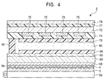
FIG. 4 is a partial sectional view which schematically
shows a liquid crystal display 2 in the second embodiment of
the present invention. As shown in FIG. 4, in the liquid
crystal display 2, a first substrate 60 and a second
substrate 70, for example, composed of a transparent glass,
which oppose each other with a liquid crystal layer 80
therebetween, are integrally bonded to each other by a
sealant 90 which is annularly provided in the periphery of
the substrates 60 and 70.
At the liquid crystal layer 80 side of the first
substrate 60, electrode layers 65 for driving the liquid
crystal layer 80, and an alignment film 66 for controlling
the alignment of liquid crystal molecules constituting the
liquid crystal layer 80 are deposited. At the liquid
crystal layer 80 side of the second substrate 70, electrode
layers 75, an overcoat film 74, and an alignment film 76 are
deposited in that order.
A polarizer 68 is provided at a side of the first
substrate 60 opposite the liquid crystal layer 80 side (on
the outer surface of the first substrate 60), and a
retardation film 77 and a polarizer 78 are deposited in that
order at a side of the second substrate 70 opposite the
liquid crystal layer 80 side (on the outer surface of the
second substrate 70).
A transflector 3 in accordance with the present
invention is placed on the outer surface (lower surface) of
the polarizer 68 of the first substrate 60 so that a
reflection film 3a faces the polarizer 68. An adhesive 4
composed of a material which does not adversely affect the
refractive index of light, such as glycerol, is filled
between the polarizer 68 and the transflector 3.
Although not shown in the drawing, a color filter
layers may be formed by printing or the like between the
substrate 60 and the electrode layers 65 so that the liquid
crystal display performs color display.
A backlight 50, which acts as a light source for
performing transmissive display in the transflective liquid
crystal display 2, is provided on the back of the
transflective liquid crystal display 2 (at the outer surface
of the first substrate 60).
The transflector 3 shown in FIG. 4 enables bright
display and widens the angle of view by efficiently
reflecting and diffusing incident light. In order to form
the reflection film 3a, a surface configuration which is the
same as that of the organic film 11 in the first embodiment
shown in FIG. 2, (i.e., the configuration in which concaves
12 are contiguously formed, the inner surface of each
concave constituting a part of a spherical surface), is
transferred to the surface of a flat resin base (a base for
the reflector) composed of a photosensitive resin or the
like formed on a substrate composed of a transparent glass
or the like, and a thin film composed of Al or Ag is
deposited thereon by vapor deposition, printing, or the like.
Additionally, as a material for the substrate described
above, a transparent material having a high transmittance,
such as glass, may be used without problems, or a flexible
film composed of a resin may be used. In some cases, the
substrate may not be provided. Additionally, the
transflector 3 can be fabricated by substantially the same
method as that for the organic film 11 in the first
embodiment shown in FIG. 3.
The surface configuration of the transflector 3 is the
same as that for the organic film 11 shown in FIG. 2.
Preferably, the depth of the concaves formed on the surface
of the transflector 3 is set at random in the range of 0.1
to 3 µm, the pitch of the adjoining concaves is set at
random in the range of 5 to 50 µm, and the inclination angle
of the inner surface of each concave is set in the range of
-30 degrees to +30 degrees. The reasons for this are the
same as those described in the first embodiment. By forming
the concaves so as to satisfy the above conditions, the
reflection efficiency of the transflector 3 can be increased.
The reflection film 3a is formed on the surface of the
transflector 3, and it reflects and scatters incident light.
The reflection film 3a preferably has a thickness of 80 to
500 Å, the same as the metallic reflection film 12 in the
first embodiment. The reason for this is the same as that
described in the first embodiment, and by setting the
thickness in the above range, bright display is also enabled
in the transmissive mode. In particular, if the thickness
is set in the range of 80 to 100 Å (i.e., 90 Å ± 10 Å),
remarkably bright display is enabled.
In the liquid crystal display 2 provided with the
transflector 3 having the structure described above, the
same as the liquid crystal display 1 in the first embodiment,
brighter, more easily visible display is performed both in
the reflective mode and in the transmissive mode compared to
the conventional liquid crystal display. This is because of
the improvement in the reflection efficiency of light due to
the surface configuration of the transflector 3 and because
of the improvement in transmittance due to a significantly
small thickness of 80 to 300 Å of the reflection film 3a
formed on the transflector 3.
Since the transflector 3 is an exterior type which is
placed on the exterior of the substrates constituting the
liquid crystal display, the transflector 3 can be mounted on
a transmissive liquid crystal display without problems, and
it is possible to produce a transflective liquid crystal
display in which bright display is performed both in the
reflective mode and in the transmissive mode. Therefore, by
using the transflector 3 of the present invention, it is
possible to manufacture a transflective liquid crystal
display without changing the structure of the liquid crystal
device except a reflector, thereby minimizing the cost for
changing the manufacturing process.
Although the present invention is applied to a passive
matrix liquid crystal display in the second embodiment, the
present invention is also applicable to a three-terminal
type (thin-film transistor: TFT) active matrix liquid
crystal display and a two-terminal type active matrix liquid
crystal display.
By applying the present invention to such active matrix
liquid crystal displays, it is possible to obtain liquid
crystal displays which provide a high-speed response and a
wide angle of view and also satisfactory visibility in both
cases when the backlight is on and when the backlight is off.
The present invention will be described in more detail
based on the examples. However, it is to be understood that
the present invention is not limited the examples described
below.
EXAMPLE 1
An organic film composed of a photosensitive resin
having a thickness of 2 µm was formed on a glass substrate
with a thickness of 0.7 mm. An aluminum film, as a metallic
reflection film, was deposited on the organic film at a
thickness of 90 Å, and an overcoat film was deposited at a
thickness of 300 Å so as to cover the organic film and the
metallic reflection film. Electrode layers and an alignment
film were deposited thereon in that order, and a substrate
for a liquid crystal display was thereby prepared. With
respect to the surface configuration of the organic film,
concaves were formed on the surface of the organic film so
as to satisfy the following conditions: the depth of the
concaves was in the range of 0.6 to 1.2 µm, the inner
surface of each concave constituting a part of a spherical
surface; the inclination angle of the inner surface of each
concave was in the range of -8 degrees to +8 degrees; and
the pitch of the adjoining concaves was in the range of 26.5
to 36.5 µm.
The substrate for the liquid crystal display and a
counter substrate provided with electrode layers, an
alignment film, etc., which was prepared separately, were
integrally bonded to each other by a sealant, and a liquid
crystal was then injected between the two substrates. A
backlight was placed on the exterior of the substrate for
the liquid crystal display, and a transflective liquid
crystal display was thereby fabricated.
EXAMPLES 2 to 5
Transflective liquid crystal displays having the same
structure as that of Example 1 were fabricated, except that
aluminum films, as metallic reflection films, with the
thicknesses described below were formed.
| | Thickness of Reflection Film |
| EXAMPLE 2 | 100 Å |
| EXAMPLE 3 | 150 Å |
| EXAMPLE 4 | 200 Å |
| EXAMPLE 5 | 300 Å |
Transflective liquid crystal displays having the same
structure as that of Example 1 were fabricated, except that
aluminum films as metallic reflection films with thicknesses
described below were formed.
| | Thickness of Reflection Film |
| COMPARATIVE EXAMPLE 1 | 75 Å |
| COMPARATIVE EXAMPLE 2 | 325 Å |
| COMPARATIVE EXAMPLE 3 | 1,000 Å |
An organic film composed of a photosensitive resin
having a thickness of 2 µm was formed on a glass substrate
with a thickness of 0.5 mm. Concaves were formed on the
surface of the organic film so as to satisfy the following
conditions: the depth of the concaves was in the range of
0.6 to 1.2 µm, the inner surface of each concave
constituting a part of a spherical surface; the inclination
angle of the inner surface of each concave was -8 degrees to
+8 degrees; and the pitch of the adjoining concaves was in
the range of 26.5 to 36.5 µm. An aluminum film with a
thickness of 90 Å, as a reflection film, was deposited on
the organic film, and thereby a transflector was fabricated.
The transflector was bonded to the back of a
transmissive liquid crystal display with an adhesive
comprising glycerol therebetween so that the reflection film
faced the liquid crystal display, and a backlight was placed
on the outside of the transflector. A transflective liquid
crystal display was thereby fabricated.
EXAMPLES 7 TO 10
Transflectors having the same structure as that of
Example 6 and transflective liquid crystal displays using
the transflectors were fabricated, except that aluminum
films, as reflection films, with the thicknesses described
below were formed.
| | Thickness of Reflection Film |
| EXAMPLE 7 | 100 Å |
| EXAMPLE 8 | 150 Å |
| EXAMPLE 9 | 200 Å |
| EXAMPLE 10 | 300 Å |
Transflectors having the same structure as that of
Example 6 and transflective liquid crystal displays using
the transflectors were fabricated, except that aluminum
films, as reflection films, with thicknesses described below
were formed.
| | Thickness of Reflection Film |
| COMPARATIVE EXAMPLE 4 | 75 Å |
| COMPARATIVE EXAMPLE 5 | 325 Å |
| COMPARATIVE EXAMPLE 6 | 1,000 Å |
With respect to the transflective liquid crystal
displays fabricated in Examples 1 to 10 and Comparative
Examples 1 to 6, display brightness was evaluated both in
the reflective mode in which the backlight was off and in
the transmissive mode in which the backlight was on. The
evaluation results were classified according to the four
levels described below, and in addition to evaluations in
the reflective mode and in the transmissive mode,
comprehensive evaluations resulting therefrom were also made.
A Remarkably bright and easily visible B Bright and easily visible C Slightly dark D Insufficiently bright but visible
First, with respect to the liquid crystal displays
having reflection films inside in Examples 1 to 5 and
Comparative Examples 1 to 3, the evaluation results are
shown in a table below. As shown in the table, with respect
to the liquid crystal displays in Examples 1 and 2, a
remarkably bright and easily visible display was obtained
both in the reflective mode and in the transmissive mode.
With respect to the liquid crystal displays in Examples 3 to
5, brightness in the transmissive mode was slightly inferior
compared to Examples 1 and 2, and accordingly, a decrease in
visibility was observed. With respect to the liquid crystal
display in which the thickness of the reflection film was
300 Å in Example 5, there was a difference in display
brightness between the transmissive mode and the reflective
mode, and although display brightness was sufficient for use,
it was slightly difficult to see the display when the liquid
crystal display was used while switching between the
transmissive mode and the reflective mode. Additionally,
with respect to the brightness in the transmissive mode in
Examples 3 to 5, the liquid crystal display in Example 3 was
brightest, the display in Example 5 was darkest, and
brightness in Example 4 was between these two results.
In contrast, in the liquid crystal display in
Comparative Example 1, display in the reflective mode was
slightly dark, and in the liquid crystal display in
Comparative Example 2, display in the transmissive mode was
slightly dark, and therefore, display was significantly more
difficult to see compared to the liquid crystal displays in
Examples 1 to 5. In the liquid crystal display in
Comparative Example 3, since substantially no light was
transmitted, display in the transmissive mode was
significantly inferior.
| | Thickness of Reflection film | Evaluation of Reflection | Evaluation of Transmittance | Comprehensive Evaluation |
| Example 1 | 90 Å | A | A | A |
| Example 2 | 100 Å | A | A | A |
| Example 3 | 150 Å | A | B | B |
| Example 4 | 200 Å | A | B | B |
| Example 5 | 300 Å | A | B | B |
| Comparative Example 1 | 75 Å | C | A | C |
| Comparative Example 2 | 325 Å | A | C | C |
| Comparative Example 3 | 1,000 Å | A | D | D |
Next, with respect to the transflective liquid crystal
displays provided with the transflectors on the exterior
thereof in Examples 6 to 10 and Comparative Examples 4 to 6,
the evaluation results are shown in a table below.
Similarly to the evaluation results of the liquid crystal
displays having reflection films inside, with respect to the
liquid crystal displays in Examples 6 and 7, in which the
thickness of the reflection film was 90 Å and 100 Å,
respectively, brightest and easily visible display was
obtained, and with respect to the liquid crystal displays in
Examples 8 to 10, brightness was slightly low compared to
Examples 6 and 7. However, with respect to the liquid
crystal display in Example 10 in which the thickness of the
reflection film was 300 Å, similar to the liquid crystal
display in Example 5, there was a difference in brightness
depending on the operation modes, and it was slightly
difficult to see the display when the liquid crystal display
was used while switching between the transmissive mode and
the reflective mode.
In Comparative Examples 4 and 6, brightness was
insufficient in the reflective mode and in the transmissive
mode, respectively, and also, since the transflectors were
provided outside, brightness tended to be more insufficient
than the liquid crystal displays having reflection films
inside in Comparative Examples 1 and 2. With respect to the
liquid crystal display in Comparative Example 6, brightness
was insufficient in the transmissive mode, the same as in
the Comparative Example 3.
| | Thickness of Reflection film | Evaluation of Reflection | Evaluation of Transmittance | Comprehensive Evaluation |
| Example 6 | 90 Å | A | A | A |
| Example 7 | 100 Å | A | A | A |
| Example 8 | 150 Å | A | B | B |
| Example 9 | 200 Å | A | B | B |
| Example 10 | 300 Å | A | B | B |
| Comparative Example 4 | 75 Å | C | A | C |
| Comparative Example 5 | 325 Å | A | C | C |
| Comparative Example 6 | 1,000 Å | A | D | D |
In the method in which the degree of brightness was
classified according to four levels, although the brightness
of the liquid crystal displays having reflection films
inside in Examples 1 and 2 and the brightness of the liquid
crystal displays provided with transflectors on the exterior
thereof in Examples 6 and 7 were evaluated as "A", a
brighter display was obtained in the liquid crystal displays
wherein light pass through fewer substrates in Examples 1
and 2 compared to the liquid crystal displays in Examples 6
and 7, respectively, both in the reflective mode and in the
transmissive mode.
The liquid crystal displays in Examples 1 to 10
provided display brightness sufficient for practical use.