EP1189055B1 - Gas detector-alarm employing hot-wire gas sensor and method of detection - Google Patents
Gas detector-alarm employing hot-wire gas sensor and method of detection Download PDFInfo
- Publication number
- EP1189055B1 EP1189055B1 EP00311201A EP00311201A EP1189055B1 EP 1189055 B1 EP1189055 B1 EP 1189055B1 EP 00311201 A EP00311201 A EP 00311201A EP 00311201 A EP00311201 A EP 00311201A EP 1189055 B1 EP1189055 B1 EP 1189055B1
- Authority
- EP
- European Patent Office
- Prior art keywords
- gas
- reference level
- cycle
- wire
- hot
- Prior art date
- Legal status (The legal status is an assumption and is not a legal conclusion. Google has not performed a legal analysis and makes no representation as to the accuracy of the status listed.)
- Expired - Lifetime
Links
Images
Classifications
-
- G—PHYSICS
- G08—SIGNALLING
- G08B—SIGNALLING SYSTEMS, e.g. PERSONAL CALLING SYSTEMS; ORDER TELEGRAPHS; ALARM SYSTEMS
- G08B21/00—Alarms responsive to a single specified undesired or abnormal condition and not otherwise provided for
- G08B21/02—Alarms for ensuring the safety of persons
- G08B21/12—Alarms for ensuring the safety of persons responsive to undesired emission of substances, e.g. pollution alarms
-
- G—PHYSICS
- G08—SIGNALLING
- G08B—SIGNALLING SYSTEMS, e.g. PERSONAL CALLING SYSTEMS; ORDER TELEGRAPHS; ALARM SYSTEMS
- G08B17/00—Fire alarms; Alarms responsive to explosion
- G08B17/10—Actuation by presence of smoke or gases, e.g. automatic alarm devices for analysing flowing fluid materials by the use of optical means
- G08B17/117—Actuation by presence of smoke or gases, e.g. automatic alarm devices for analysing flowing fluid materials by the use of optical means by using a detection device for specific gases, e.g. combustion products, produced by the fire
-
- G—PHYSICS
- G01—MEASURING; TESTING
- G01N—INVESTIGATING OR ANALYSING MATERIALS BY DETERMINING THEIR CHEMICAL OR PHYSICAL PROPERTIES
- G01N25/00—Investigating or analyzing materials by the use of thermal means
- G01N25/18—Investigating or analyzing materials by the use of thermal means by investigating thermal conductivity
Definitions
- This invention relates to a gas detector-alarm employing a hot-wire gas sensor and more particularly to a technology to reduce electric power to heat the heat wire.
- heating time must be increased, with a resulting increase in power consumption during the time when gas is present.
- a gas detector-alarm determines gas concentration by means of a hot-wire gas sensor to which pulsed actuating current is supplied.
- Said gas detector-alarm has an actuating-current control unit that supplies said pulsed actuating current with a cycle T0 when the concentration of gas detected by said hot-wire gas sensor is lower than a first reference level and with a cycle TI, which is shorter than said cycle T0, at least once when the concentration is higher than a second reference level.
- the current-supply cycle is reduced to T0 in preparation for further concentration increase.
- gas /0 concentration is found to exceed the second reference level and reaches the warning level, the current-supply cycle is increased to Ti to save electricity in the presence of high-concentration gas.
- the object of this invention is to provide a gas detector-alarm employing a hot-wire gas sensor for detecting gas concentration by means of a pulsed actuating signal supplied thereto, the gas detector-alarm comprises:
- the present invention also provides a method of detecting a gas concentration using a hot-wire gas sensor, the method comprises the steps of:
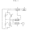
- Fig. 1 is a block diagram of an embodiment of a gas detector-alarm according to this invention.
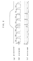
- Fig. 2 is a waveform showing the operation of the same embodiment.
- FIG. 1 shows an embodiment of a gas detector-alarm according to this invention.
- a hot-wire gas sensor 1 alters electric resistance by detecting the difference in thermal conductivity of gases and comprises a bridge formed of a temperature-compensated resistor 2 and fixed resistors 3 and 4.
- the actuating power terminal of the hot-wire gas sensor is connected to a power supply 6 via a switching device 5, whereas the detecting terminal thereof is connected to an actuating power control 7 that controls the operation of the switching device 5.
- the actuating power control 7 supplies a pulsed actuating power with a time width t0 as shown in Figs. 2 (a) to 2 (c) .
- the actuating power control 7 is adapted to supply the actuating power with a cycle T0 when the hot-wire gas sensor 1 does not detect any gas or the bridge outputs a detection signal representing a detection output lower than the noise level L0 and with a cycle T1, which is shorter than the cycle T0, when the bridge outputs a detection signal representing a gas concentration higher than a predetermined concentration or above a warning level L1.
- Reference numeral 8 designates a measuring circuit that actuates an alarm indicator 9 based on the detection signal from the bridge.
- the time width t0 of the actuating power is set at a length of time in which the hot-wire gas sensor 1 is heated from ordinary temperature to a temperature at which normal gas detection can be made.
- the temperature permitting normal gas detection and time width t0 are several hundreds degrees centigrade and approximately 2 seconds, respectively.
- the cycle T1 is not shorter than an interval of time between the start of measurement by the hot-wire gas sensor and a time point at which a gas admitted into a cell in the hot-wire gas sensor 1 is replaced that is long enough to permit an alarm to be triggered within a given time after the concentration of the gas has exceeded a predetermined level.
- the cycle T1 in this embodiment is set at 4 seconds.
- the actuating power control 7 of this embodiment supplies the pulsed actuating power to the bridge that constitutes the gas sensor 1 with a cycle T0. Accordingly, the gas sensor 1 becomes quiescent after it has been heated to a high enough temperature to permit gas detection, thus eliminating the waste of power by the gas sensor 1.
- the actuating power control 7 When gas leakage occurs and the detection signal exceeds level L1, the actuating power control 7 shortens the power supply cycle from T0 to T1. Even if, as such, gas concentration increases suddenly to above the warning level, a detection signal representing a concentration above warning level L3 is triggered whereby the measuring circuit 8 promptly actuates the alarm indicator 9 to trigger an alarm. After the alarm has been provided, the actuating power control 7 lengthens the power supply cycle to T0 and thereby eliminates the waste of power.
- the hot wire is coated with a catalytic substance that reacts with the gas detected to prevent overheating by high-concentration gases and possible shortening of the service life of the gas sensor.
- a hot wire coated with a catalytic or other active substance also performs the same function by detecting the heat of reaction as resistance change.
Landscapes
- Business, Economics & Management (AREA)
- General Physics & Mathematics (AREA)
- Physics & Mathematics (AREA)
- Emergency Management (AREA)
- General Health & Medical Sciences (AREA)
- Toxicology (AREA)
- Health & Medical Sciences (AREA)
- Environmental & Geological Engineering (AREA)
- Engineering & Computer Science (AREA)
- Chemical & Material Sciences (AREA)
- Analytical Chemistry (AREA)
- Investigating Or Analyzing Materials By The Use Of Electric Means (AREA)
- Emergency Alarm Devices (AREA)
Description
- This invention relates to a gas detector-alarm employing a hot-wire gas sensor and more particularly to a technology to reduce electric power to heat the heat wire.
- With gas detectors that determine gas concentration by means of a gas sensor with a hot wire, most of electric power supplied thereto is consumed by the gas sensor. As such, provisions are made to supply electricity to the hot wire at given intervals for the shortest possible but long enough time to permit gas detection, as proposed in Japanese Provisional Utility Model Publication No. 14595 of 1987, and, in addition to the above, to ensure continued supply of electricity when the presence of gas is detected, as proposed in Japanese Provisional Patent Publication No. 233699 of 1991 (JP-62-014595U).
- To detect transient changes in gas concentration after the occurrence of gas leakage by these methods, however, heating time must be increased, with a resulting increase in power consumption during the time when gas is present.
- The latter of the above two methods, although capable of detecting transient changes in gas concentration, involves the problem that power consumption increases when the concentration of gas present exceeds a certain level.
- A gas detector-alarm according to this invention determines gas concentration by means of a hot-wire gas sensor to which pulsed actuating current is supplied. Said gas detector-alarm has an actuating-current control unit that supplies said pulsed actuating current with a cycle T0 when the concentration of gas detected by said hot-wire gas sensor is lower than a first reference level and with a cycle TI, which is shorter than said cycle T0, at least once when the concentration is higher than a second reference level.
- When gas concentration exceeds the first reference level, the current-supply cycle is reduced to T0 in preparation for further concentration increase. When gas /0 concentration is found to exceed the second reference level and reaches the warning level, the current-supply cycle is increased to Ti to save electricity in the presence of high-concentration gas.
- The object of this invention is to provide a gas detector-alarm employing a hot-wire gas sensor for detecting gas concentration by means of a pulsed actuating signal supplied thereto, the gas detector-alarm comprises:
- actuating power control means arranged to apply, in use, a pulsed actuating signal having a constant on-time t0 with a cycle T0 when the gas concentration detected by said hot-wire gas sensor is lower than a first reference level; to apply, in use, a pulsed actuating signal having a constant on-time t0 with a cycle T1 that is shorter than the cycle T0 when the gas concentration is detected as exceeding a second reference level which is higher than the first reference level; and to change, in use, the applied cycle of the pulsed actuating signal having a constant on-time t0 to T0 when the gas concentration is detected as exceeding a third reference level which is higher than the second reference level; and
- means to raise an alarm at a point in time when it is detected that the gas concentration has exceeded the third reference level.
- The present invention also provides a method of detecting a gas concentration using a hot-wire gas sensor, the method comprises the steps of:
- supplying the hot-wire gas sensor with a pulsed actuating signal having a constant on-time t0 with a cycle T0 when the gas concentration detected by said hot-wire gas sensor is lower than a first reference level;
- supplying the hot-wire gas sensor with a pulsed actuating signal having a constant on-time t0 with a cycle T1 that is shorter than the cycle T0 when the gas concentration is detected as exceeding a second reference level which is higher than the first reference level;
- changing the applied cycle of the pulsed actuating signal having a constant on-time t0 to T0 when the gas concentration is detected as exceeding a third reference level which is higher than the second reference level; and
- raising an alarm at a point in time when it is detected that the gas concentration has exceeded the third reference level.
- In the Drawings:
Fig. 1 is a block diagram of an embodiment of a gas detector-alarm according to this invention. Fig. 2 is a waveform showing the operation of the same embodiment. - Fig. 1 shows an embodiment of a gas detector-alarm according to this invention. A hot-wire gas sensor 1 alters electric resistance by detecting the difference in thermal conductivity of gases and comprises a bridge formed of a temperature-compensated
resistor 2 and fixed resistors 3 and 4. The actuating power terminal of the hot-wire gas sensor is connected to apower supply 6 via aswitching device 5, whereas the detecting terminal thereof is connected to an actuatingpower control 7 that controls the operation of theswitching device 5. - The actuating
power control 7 supplies a pulsed actuating power with a time width t0 as shown in Figs. 2 (a) to 2 (c) . The actuatingpower control 7 is adapted to supply the actuating power with a cycle T0 when the hot-wire gas sensor 1 does not detect any gas or the bridge outputs a detection signal representing a detection output lower than the noise level L0 and with a cycle T1, which is shorter than the cycle T0, when the bridge outputs a detection signal representing a gas concentration higher than a predetermined concentration or above a warning level L1.Reference numeral 8 designates a measuring circuit that actuates an alarm indicator 9 based on the detection signal from the bridge. - The time width t0 of the actuating power is set at a length of time in which the hot-wire gas sensor 1 is heated from ordinary temperature to a temperature at which normal gas detection can be made. In the case of this embodiment, the temperature permitting normal gas detection and time width t0 are several hundreds degrees centigrade and approximately 2 seconds, respectively.
- The cycle T1 is not shorter than an interval of time between the start of measurement by the hot-wire gas sensor and a time point at which a gas admitted into a cell in the hot-wire gas sensor 1 is replaced that is long enough to permit an alarm to be triggered within a given time after the concentration of the gas has exceeded a predetermined level. The cycle T1 in this embodiment is set at 4 seconds.
- In the absence of gas, the actuating
power control 7 of this embodiment supplies the pulsed actuating power to the bridge that constitutes the gas sensor 1 with a cycle T0. Accordingly, the gas sensor 1 becomes quiescent after it has been heated to a high enough temperature to permit gas detection, thus eliminating the waste of power by the gas sensor 1. - When gas leakage occurs and the detection signal exceeds level L1, the actuating
power control 7 shortens the power supply cycle from T0 to T1. Even if, as such, gas concentration increases suddenly to above the warning level, a detection signal representing a concentration above warning level L3 is triggered whereby themeasuring circuit 8 promptly actuates the alarm indicator 9 to trigger an alarm. After the alarm has been provided, the actuatingpower control 7 lengthens the power supply cycle to T0 and thereby eliminates the waste of power. The hot wire is coated with a catalytic substance that reacts with the gas detected to prevent overheating by high-concentration gases and possible shortening of the service life of the gas sensor. - While the embodiment described above detects resistance changes caused by the temperature changes of the hot wire due to the difference in thermal conductivity of gases, a hot wire coated with a catalytic or other active substance also performs the same function by detecting the heat of reaction as resistance change.
Claims (2)
- A gas detector-alarm employing a hot-wire gas sensor for detecting gas concentration by means of a pulsed actuating signal supplied thereto, the gas detector-alarm comprising:actuating power control means arranged to apply, in use, a pulsed actuating signal having a constant on-time t0 with a cycle T0 when the gas concentration detected by said hot-wire gas sensor is lower than a first reference level; to apply, in use, a pulsed actuating signal having a constant on-time t0 with a cycle T1 that is shorter than the cycle T0 when the gas concentration is detected as exceeding a second reference level which is higher than the first reference level; and to change, in use, the applied cycle of the pulsed actuating signal having a constant on-time t0 to T0 when the gas concentration is detected as exceeding a third reference level which is higher than the second reference level; andmeans to raise an alarm at a point in time when it is detected that the gas concentration has exceeded the third reference level.
- A method of detecting a gas concentration using a hot-wire gas sensor, the method comprising the steps of:supplying the hot-wire gas sensor with a pulsed actuating signal having a constant on-time t0 with a cycle T0 when the gas concentration detected by said hot-wire gas sensor is lower than a first reference level;supplying the hot-wire gas sensor with a pulsed actuating signal having a constant on-time t0 with a cycle T1 that is shorter than the cycle T0 when the gas concentration is detected as exceeding a second reference level which is higher than the first reference level;changing the applied cycle of the pulsed actuating signal having a constant on-time t0 to T0 when the gas concentration is detected as exceeding a third reference level which is higher than the second reference level; andraising an alarm at a point in time when it is detected that the gas concentration has exceeded the third reference level.
Applications Claiming Priority (2)
| Application Number | Priority Date | Filing Date | Title |
|---|---|---|---|
| JP2000280009 | 2000-09-14 | ||
| JP2000280009A JP3672082B2 (en) | 2000-09-14 | 2000-09-14 | Gas detection alarm device using hot-wire gas sensor |
Publications (3)
| Publication Number | Publication Date |
|---|---|
| EP1189055A2 EP1189055A2 (en) | 2002-03-20 |
| EP1189055A3 EP1189055A3 (en) | 2002-11-27 |
| EP1189055B1 true EP1189055B1 (en) | 2006-02-22 |
Family
ID=18764920
Family Applications (1)
| Application Number | Title | Priority Date | Filing Date |
|---|---|---|---|
| EP00311201A Expired - Lifetime EP1189055B1 (en) | 2000-09-14 | 2000-12-14 | Gas detector-alarm employing hot-wire gas sensor and method of detection |
Country Status (4)
| Country | Link |
|---|---|
| US (1) | US6348872B1 (en) |
| EP (1) | EP1189055B1 (en) |
| JP (1) | JP3672082B2 (en) |
| DE (1) | DE60026124T2 (en) |
Families Citing this family (13)
| Publication number | Priority date | Publication date | Assignee | Title |
|---|---|---|---|---|
| PT1516299E (en) * | 2002-06-24 | 2007-02-28 | Angeleyel Inc | Alarm |
| JP3929845B2 (en) * | 2002-07-26 | 2007-06-13 | 理研計器株式会社 | Combustible gas detector |
| US7737700B2 (en) * | 2005-11-23 | 2010-06-15 | Ust Umweltsensortechnik Gmbh | Arrangement and method for detecting air ingredients |
| US7833482B2 (en) * | 2006-12-29 | 2010-11-16 | Honeywell International Inc. | Low power combustible gas sensor |
| WO2012105423A1 (en) * | 2011-02-04 | 2012-08-09 | 富士電機株式会社 | Battery-powered gas alarm and control device thereof |
| JP5829841B2 (en) * | 2011-06-21 | 2015-12-09 | 矢崎エナジーシステム株式会社 | Alarm |
| GB2497295A (en) | 2011-12-05 | 2013-06-12 | Gassecure As | Method and system for gas detection |
| JP6334224B2 (en) * | 2014-03-26 | 2018-05-30 | 新コスモス電機株式会社 | Contact combustion type gas sensor and driving method thereof |
| JP6364877B2 (en) * | 2014-03-31 | 2018-08-01 | 富士電機株式会社 | Battery-powered gas alarm and its control device |
| JP6444781B2 (en) * | 2015-03-10 | 2018-12-26 | 新コスモス電機株式会社 | Gas detection device and control method thereof |
| JP6883482B2 (en) * | 2016-08-26 | 2021-06-09 | エイブリック株式会社 | Sensor circuit |
| CN110950545A (en) * | 2018-09-27 | 2020-04-03 | 天津滨海光热反射技术有限公司 | Coated glass's lacquer spraying room |
| AU2020397698A1 (en) * | 2019-12-05 | 2022-05-26 | Tyco Fire Products Lp | Fire suppression system for a battery enclosure |
Family Cites Families (9)
| Publication number | Priority date | Publication date | Assignee | Title |
|---|---|---|---|---|
| FR2193487A5 (en) * | 1972-07-21 | 1974-02-15 | Onera (Off Nat Aerospatiale) | |
| US4340885A (en) * | 1979-09-24 | 1982-07-20 | Super Shops, Inc. | Gas detector |
| US4369647A (en) * | 1980-03-21 | 1983-01-25 | New Cosmos Electric Company Limited | Gas leakage detector |
| CA1216330A (en) * | 1983-02-07 | 1987-01-06 | Junji Manaka | Low power gas detector |
| JPS61209347A (en) * | 1985-03-13 | 1986-09-17 | Shinkosumosu Denki Kk | Hot wire semiconductor type gas alarm |
| JP2791472B2 (en) * | 1988-02-02 | 1998-08-27 | フィガロ技研株式会社 | Gas detector |
| US4966033A (en) * | 1988-06-15 | 1990-10-30 | Hitachi, Ltd. | Air flow metering apparatus for internal combustion engines |
| JPH06105234B2 (en) * | 1992-10-20 | 1994-12-21 | フィガロ技研株式会社 | Gas detector |
| US5608384A (en) * | 1992-10-23 | 1997-03-04 | Sentech Corporation | Method and apparatus for monitoring for the presence of a gas |
-
2000
- 2000-09-14 JP JP2000280009A patent/JP3672082B2/en not_active Expired - Fee Related
- 2000-10-23 US US09/693,917 patent/US6348872B1/en not_active Expired - Lifetime
- 2000-12-14 DE DE60026124T patent/DE60026124T2/en not_active Expired - Lifetime
- 2000-12-14 EP EP00311201A patent/EP1189055B1/en not_active Expired - Lifetime
Also Published As
| Publication number | Publication date |
|---|---|
| DE60026124T2 (en) | 2006-08-17 |
| DE60026124D1 (en) | 2006-04-27 |
| EP1189055A3 (en) | 2002-11-27 |
| US6348872B1 (en) | 2002-02-19 |
| EP1189055A2 (en) | 2002-03-20 |
| JP2002090328A (en) | 2002-03-27 |
| JP3672082B2 (en) | 2005-07-13 |
Similar Documents
| Publication | Publication Date | Title |
|---|---|---|
| US6348872B1 (en) | Gas detector-alarm employing hot-wire gas sensor | |
| US20040113802A1 (en) | Gas detection instrument and method for its operation | |
| US5517182A (en) | Method for CO detection and its apparatus | |
| EP2570802A1 (en) | Internal combustion engine controller | |
| EP3153849B1 (en) | Gas sensor and method for operating said gas sensor | |
| KR20140137387A (en) | Method and devices for operating a heatable exhaust sensor | |
| JPH0426702B2 (en) | ||
| JP3929846B2 (en) | Intermittent drive type combustible gas detector | |
| JP3885648B2 (en) | Safety sensor | |
| JP2002082083A (en) | Gas detector | |
| JP2004158340A (en) | Package type fuel cell power generator | |
| JP3809897B2 (en) | Combustible gas concentration measuring device | |
| JP2001188056A (en) | Gas detector | |
| JP2840652B2 (en) | Gas detector | |
| JP2001194329A (en) | Gas sensor | |
| JPS62198435U (en) | ||
| JP3549322B2 (en) | Gas detection method and gas detection device | |
| JP2005017231A (en) | Liquid state detection device | |
| JP4803658B2 (en) | Intermittent drive type combustible gas detector | |
| JP2004061214A (en) | Combustible gas detector | |
| JP2000193621A (en) | Gas detection method and device | |
| JPH0241741Y2 (en) | ||
| JP2014035267A (en) | Gas detector | |
| JPS626530Y2 (en) | ||
| JP3885649B2 (en) | Safety sensor |
Legal Events
| Date | Code | Title | Description |
|---|---|---|---|
| PUAI | Public reference made under article 153(3) epc to a published international application that has entered the european phase |
Free format text: ORIGINAL CODE: 0009012 |
|
| AK | Designated contracting states |
Kind code of ref document: A2 Designated state(s): AT BE CH CY DE DK ES FI FR GB GR IE IT LI LU MC NL PT SE TR |
|
| AX | Request for extension of the european patent |
Free format text: AL;LT;LV;MK;RO;SI |
|
| PUAL | Search report despatched |
Free format text: ORIGINAL CODE: 0009013 |
|
| AK | Designated contracting states |
Kind code of ref document: A3 Designated state(s): AT BE CH CY DE DK ES FI FR GB GR IE IT LI LU MC NL PT SE TR |
|
| AX | Request for extension of the european patent |
Free format text: AL;LT;LV;MK;RO;SI |
|
| 17P | Request for examination filed |
Effective date: 20030516 |
|
| AKX | Designation fees paid |
Designated state(s): BE DE FR GB NL |
|
| 17Q | First examination report despatched |
Effective date: 20050324 |
|
| GRAP | Despatch of communication of intention to grant a patent |
Free format text: ORIGINAL CODE: EPIDOSNIGR1 |
|
| RTI1 | Title (correction) |
Free format text: GAS DETECTOR-ALARM EMPLOYING HOT-WIRE GAS SENSOR AND METHOD OF DETECTION |
|
| RIN1 | Information on inventor provided before grant (corrected) |
Inventor name: OTANI, SEIICHI Inventor name: YASUDA, SHOEI |
|
| GRAS | Grant fee paid |
Free format text: ORIGINAL CODE: EPIDOSNIGR3 |
|
| GRAA | (expected) grant |
Free format text: ORIGINAL CODE: 0009210 |
|
| AK | Designated contracting states |
Kind code of ref document: B1 Designated state(s): BE DE FR GB NL |
|
| REG | Reference to a national code |
Ref country code: GB Ref legal event code: FG4D |
|
| REF | Corresponds to: |
Ref document number: 60026124 Country of ref document: DE Date of ref document: 20060427 Kind code of ref document: P |
|
| ET | Fr: translation filed | ||
| PLBE | No opposition filed within time limit |
Free format text: ORIGINAL CODE: 0009261 |
|
| STAA | Information on the status of an ep patent application or granted ep patent |
Free format text: STATUS: NO OPPOSITION FILED WITHIN TIME LIMIT |
|
| 26N | No opposition filed |
Effective date: 20061123 |
|
| PGFP | Annual fee paid to national office [announced via postgrant information from national office to epo] |
Ref country code: GB Payment date: 20101215 Year of fee payment: 11 |
|
| PGFP | Annual fee paid to national office [announced via postgrant information from national office to epo] |
Ref country code: DE Payment date: 20101215 Year of fee payment: 11 |
|
| PGFP | Annual fee paid to national office [announced via postgrant information from national office to epo] |
Ref country code: NL Payment date: 20111220 Year of fee payment: 12 Ref country code: FR Payment date: 20111219 Year of fee payment: 12 |
|
| PGFP | Annual fee paid to national office [announced via postgrant information from national office to epo] |
Ref country code: BE Payment date: 20111229 Year of fee payment: 12 |
|
| BERE | Be: lapsed |
Owner name: *RIKEN KEIKI CO. LTD Effective date: 20121231 |
|
| REG | Reference to a national code |
Ref country code: NL Ref legal event code: V1 Effective date: 20130701 |
|
| GBPC | Gb: european patent ceased through non-payment of renewal fee |
Effective date: 20121214 |
|
| REG | Reference to a national code |
Ref country code: FR Ref legal event code: ST Effective date: 20130830 |
|
| PG25 | Lapsed in a contracting state [announced via postgrant information from national office to epo] |
Ref country code: BE Free format text: LAPSE BECAUSE OF NON-PAYMENT OF DUE FEES Effective date: 20121231 |
|
| REG | Reference to a national code |
Ref country code: DE Ref legal event code: R119 Ref document number: 60026124 Country of ref document: DE Effective date: 20130702 |
|
| PG25 | Lapsed in a contracting state [announced via postgrant information from national office to epo] |
Ref country code: NL Free format text: LAPSE BECAUSE OF NON-PAYMENT OF DUE FEES Effective date: 20130701 Ref country code: DE Free format text: LAPSE BECAUSE OF NON-PAYMENT OF DUE FEES Effective date: 20130702 |
|
| PG25 | Lapsed in a contracting state [announced via postgrant information from national office to epo] |
Ref country code: GB Free format text: LAPSE BECAUSE OF NON-PAYMENT OF DUE FEES Effective date: 20121214 Ref country code: FR Free format text: LAPSE BECAUSE OF NON-PAYMENT OF DUE FEES Effective date: 20130102 |