EP1188955B1 - Hydraulic chain tensioner with no-return device for the piston - Google Patents
Hydraulic chain tensioner with no-return device for the piston Download PDFInfo
- Publication number
- EP1188955B1 EP1188955B1 EP00830616A EP00830616A EP1188955B1 EP 1188955 B1 EP1188955 B1 EP 1188955B1 EP 00830616 A EP00830616 A EP 00830616A EP 00830616 A EP00830616 A EP 00830616A EP 1188955 B1 EP1188955 B1 EP 1188955B1
- Authority
- EP
- European Patent Office
- Prior art keywords
- cylinder
- piston
- tensioner
- pad
- tensioner according
- Prior art date
- Legal status (The legal status is an assumption and is not a legal conclusion. Google has not performed a legal analysis and makes no representation as to the accuracy of the status listed.)
- Expired - Lifetime
Links
Images


Classifications
-
- F—MECHANICAL ENGINEERING; LIGHTING; HEATING; WEAPONS; BLASTING
- F16—ENGINEERING ELEMENTS AND UNITS; GENERAL MEASURES FOR PRODUCING AND MAINTAINING EFFECTIVE FUNCTIONING OF MACHINES OR INSTALLATIONS; THERMAL INSULATION IN GENERAL
- F16H—GEARING
- F16H7/00—Gearings for conveying rotary motion by endless flexible members
- F16H7/08—Means for varying tension of belts, ropes, or chains
- F16H7/0848—Means for varying tension of belts, ropes, or chains with means for impeding reverse motion
- F16H2007/0853—Ratchets
-
- F—MECHANICAL ENGINEERING; LIGHTING; HEATING; WEAPONS; BLASTING
- F16—ENGINEERING ELEMENTS AND UNITS; GENERAL MEASURES FOR PRODUCING AND MAINTAINING EFFECTIVE FUNCTIONING OF MACHINES OR INSTALLATIONS; THERMAL INSULATION IN GENERAL
- F16H—GEARING
- F16H7/00—Gearings for conveying rotary motion by endless flexible members
- F16H7/08—Means for varying tension of belts, ropes, or chains
- F16H7/0848—Means for varying tension of belts, ropes, or chains with means for impeding reverse motion
- F16H2007/0859—Check valves
-
- F—MECHANICAL ENGINEERING; LIGHTING; HEATING; WEAPONS; BLASTING
- F16—ENGINEERING ELEMENTS AND UNITS; GENERAL MEASURES FOR PRODUCING AND MAINTAINING EFFECTIVE FUNCTIONING OF MACHINES OR INSTALLATIONS; THERMAL INSULATION IN GENERAL
- F16H—GEARING
- F16H7/00—Gearings for conveying rotary motion by endless flexible members
- F16H7/08—Means for varying tension of belts, ropes, or chains
- F16H2007/0876—Control or adjustment of actuators
- F16H2007/0878—Disabling during transport
Definitions
- the invention refers to devices for tensioning drive transmission means, such as chains.
- a timing system of an internal combustion engine can be controlled by means of a chain drive, in which a chain is wound on two or more sprockets, one of which is a driving sprocket and takes the motion from the drive shaft to transmit it to the camshaft.
- shoe tensioning devices Since for reasons of adjustment, wear on materials and take-up of slack it is often necessary to compensate for a certain loose on the chain, the use of shoe tensioning devices is known to the art, in which a shoe is biased with an adjustable force against a run or branch of the chain.
- cylinder/piston tensioners in which a fixed member of a cylinder/piston assembly (generally the cylinder) is mounted on the engine block and a movable member (generally the piston) is slidable with respect to the fixed members and acts against the shoe placed in contact with the chain, to tension it.
- Said tensioning devices can be further divided into two categories: those that are disposed inside the engine block, and therefore require opening of the engine for fitting and, if necessary, for removal, and those of the so-called cartridge type, which are screwed into the engine block or the head from the outside, these latter devices undoubtedly being more convenient as far as ease of fitting and removal is concerned, in that opening of the engine is not necessary.
- the invention refers in particular to this second type.
- no-return devices for the piston which are easily applied in tensioning devices situated inside the engine block, where there are no particular problems of space.
- These devices normally consist of a rod provided with a rack located outside and parallel to the cylinder/piston assembly and engaged by a pawl disposed in the body of the tensioning device and elastically biased against said rack, which is allowed to slide only in the direction of outward travel of the piston and is pulled by the piston in this direction, when the latter protrudes from the cylinder because of slackening of the chain.
- the rod with rack being prevented from returning inside the body of the tensioner, forms a stop means for the shoe that acts against the chain, thus preventing the above mentioned flapping of the chain.
- the rod with rack engages with a shoulder of the piston situated at a certain distance (of the order of a few millimetres) from the free end of the piston, so as to allow a certain degree elasticity of the system, that is a certain controlled return of the piston.
- cartridge type tensioning devices said solution is not practicable, in that in said devices it is not possible to dispose members that protrude beyond the outer profile of the cylinder.
- the maximum size of said devices is in fact given by the thread that screws into the threaded hole in the engine block.
- Document EP-A-0 106 325 discloses a tensioning device to be disposed inside the engine block, comprising a cylinder, a hollow piston axially slidable in the inner bore of the cylinder and a device preventing uncontrolled return of the piston into the cylinder, where the hollow piston is axially slidable in the cylinder under the action of elastic biasing means acting between the cylinder and the piston and of pressurized fluid fed into the cylinder bore and an upper end of the piston acts on a movable shoe to tension a chain or belt.
- the object of the invention is to eliminate said drawbacks, providing a tensioning device for chain tensioners of the cartridge type, provided with a no-return device for the piston completely contained within the bulk of the cylinder.
- Another object of the invention is that of providing such a cartridge tensioner, in which said no-return device for the piston is of simple and economical design, and is highly reliable.
- At least one set of teeth or rack extending longitudinally of the piston and accessible through at least one window in the cylinder wall is provided, and in register with said window a toothed pad is disposed, able to engage with the teeth of the rack, so as to allow sliding thereof only in a direction of protrusion of the piston from the cylinder, said pad being elastically biased against the rack by the action of a spring.
- the longitudinal extent of the pad is advantageously smaller than the corresponding extent of the aperture or window made in the wall of the cylinder, and the pad is suitably guided in a seat made in the wall of the cylinder, so as to allow the piston a certain play, and thus its possible controlled elastic return.
- the pad acting against the rack can be mounted without any possibility of axial sliding and a second small piston, axially protruding from the end of the main piston can be provided able to retract in the event of excessive force being exerted against it, thus maintaining the elastic characteristic of the piston.
- Figure 2 diagrammatically shows a chain drive to which the tensioner according to the invention can be applied.
- a driving wheel 2 and a driven wheel 3 are shown, on which a chain 1 is wound, a taut branch or run of which (the lower one in the figure) is guided by a suitable guide 4, a slack branch or run (the upper one in the figure) is tensioned by means of a shoe 5, swingable around a pin 6, and pushed against the corresponding run of the chain by a tensioning device, indicated as a whole by reference numeral 10, which in this case is a cartridge tensioner, of the type previously mentioned, that is screwed into the engine block or into the head.
- a tensioning device indicated as a whole by reference numeral 10 which in this case is a cartridge tensioner, of the type previously mentioned, that is screwed into the engine block or into the head.
- the cartridge type tensioner 10 comprises a body or cylinder 11 and a piston 12 slidably housed in a bore 13 of the cylinder 11.
- the cylinder 11 has, at the opposite end to that from which the piston 12 extends, a head 14, and a thread 15 on its skirt, in proximity to the head 14, for screwing into a threaded hole in the engine block or in the engine head.
- the piston 12 is hollow on the inside and houses a pressure spring 16 acting between a bottom of the bore 13 and a head end 17 of the piston 12.
- the bore 13 communicates with a source of pressurized fluid, generally oil, through an opening 18, and a check valve 19, in a manner that is per se known and therefore not described.
- the valve 19 is normally equipped with a sealing disc 19' that allows a calibrated return of the fluid to impart a certain degree of dampening or elasticity to the piston 12.
- the piston sleeve 12 In order to prevent uncontrolled re-entry of the piston 12 into the cylinder 11, in the event of even partial emptying of the bore 13, in accordance with the invention there is on the piston sleeve 12 at least one longitudinal rack 20 with which a toothed pad 21 engages, passing through an aperture 22 formed in the side wall of the cylinder.
- the axial or longitudinal extent of the toothed pad 21 is less than the corresponding extent of the aperture 22, so that said pad can have a certain axial sliding, guided by a pad base 23, which slides in a corresponding seat 24 formed in the wall of the cylinder 11, adjacent the aperture 22.
- the pad 21 is pressed against the rack 20 by the action of a spring 25 consisting in particular of an open annular ring of spring steel which is fitted in a corresponding annular seat 26 formed in the wall of the cylinder and having a width substantially corresponding to the sum of the longitudinal dimensions of said aperture 22 and of said seat 24.
- the spring 25 is disposed above the pad 21, keeping it constantly pressed against the teeth of the rack 20, so as to prevent uncontrolled re-entry of the piston 12, except for take-up of slack due to the pad 21 being housed loosely in the aperture 22.
- a single rack 20 involving a small portion of the circumference of the piston 12 is shown. It is nevertheless clear that a plurality of parallel racks can be provided on the sleeve of the piston 12, or even a single rack extending for the whole circumference of the piston. Correspondingly a plurality of toothed pads 21, housed in an equal number of apertures 22 provided circumferentially in the wall of the cylinder 11, or a single pad with a plurality of circumferentially spaced sets of teeth can be provided.
- the biasing action against the rack would again be exerted by the spring 25 in the form of a split ring or the like.
- annular cavity 30 is provided on the skirt of the piston 12, near the head end 17 thereof, whilst two other annular cavities 31 and 32 of different sizes are formed on the inside of the wall of the cylinder 11, near the free end thereof opposite to the head 14.
- a split ring 33 is interposed, which elastically presses against the inner wall of the cylinder.
- Figure 4 shows the tensioner 10 in the position after fitting in the engine block, with the piston protruding from the cylinder for a small portion of its length.
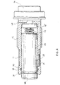
- Figure 5 shows the tensioner with the piston in the position of maximum outward travel from the cylinder, and thus at the end of its stroke.
- the toothed pad 21 is not provided with the possibility of axial sliding, for example by making it of the same length as the aperture 22 and/or lengthening its base 23 to bring it into abutment with the shoulder of the corresponding seat 24, as shown in the figure.
- a hole 40 is provided at the head end 17 of the piston 12 for passage of a small piston 41, whose base 42 abuts internally against said head end 17 of the main piston 12, biased by the screw 16 and by the action of the pressurized fluid in the bore 13.
- An O-ring 43 is inserted in an annular groove of said hole 40 to ensure the seal of the small piston 41.
Landscapes
- Engineering & Computer Science (AREA)
- General Engineering & Computer Science (AREA)
- Mechanical Engineering (AREA)
- Devices For Conveying Motion By Means Of Endless Flexible Members (AREA)
Description
- The invention refers to devices for tensioning drive transmission means, such as chains.
- In particular reference will be made to chain transmission means on vehicles.
- A timing system of an internal combustion engine can be controlled by means of a chain drive, in which a chain is wound on two or more sprockets, one of which is a driving sprocket and takes the motion from the drive shaft to transmit it to the camshaft.
- Since for reasons of adjustment, wear on materials and take-up of slack it is often necessary to compensate for a certain loose on the chain, the use of shoe tensioning devices is known to the art, in which a shoe is biased with an adjustable force against a run or branch of the chain.
- Various means are known for biasing the tensioning shoe against the chain. Among these, the most frequently used are cylinder/piston tensioners, in which a fixed member of a cylinder/piston assembly (generally the cylinder) is mounted on the engine block and a movable member (generally the piston) is slidable with respect to the fixed members and acts against the shoe placed in contact with the chain, to tension it.
- In these tensioning devices, the piston is pushed out of the cylinder, towards the shoe disposed against a run of the chain by the combined action of a spring and of pressurized oil fed into the cylinder chamber.
- Any slackening of the chain due to heating, wear and time is compensated by the piston extending out of the cylinder, under the action of said biasing means.
- Said tensioning devices can be further divided into two categories: those that are disposed inside the engine block, and therefore require opening of the engine for fitting and, if necessary, for removal, and those of the so-called cartridge type, which are screwed into the engine block or the head from the outside, these latter devices undoubtedly being more convenient as far as ease of fitting and removal is concerned, in that opening of the engine is not necessary.
- The invention refers in particular to this second type.
- It sometimes happens, especially during starting of the engine, that the cylinder chamber is completely or partially emptied of oil. In this case, the force of the pressure spring alone may not be sufficient to keep the chain under control. Thus flapping of the chain is generated, which tends to push the piston inside the cylinder, until the oil in the cylinder reaches working pressure, which may take a few seconds. This flapping of the chain, besides producing an annoying noise, can in the long run cause damage to the whole chain drive assembly, including the tensioner.
- In order to avoid this drawback, no-return devices for the piston have been proposed, which are easily applied in tensioning devices situated inside the engine block, where there are no particular problems of space. These devices normally consist of a rod provided with a rack located outside and parallel to the cylinder/piston assembly and engaged by a pawl disposed in the body of the tensioning device and elastically biased against said rack, which is allowed to slide only in the direction of outward travel of the piston and is pulled by the piston in this direction, when the latter protrudes from the cylinder because of slackening of the chain. The rod with rack, being prevented from returning inside the body of the tensioner, forms a stop means for the shoe that acts against the chain, thus preventing the above mentioned flapping of the chain. In order not to make the system excessively rigid, the rod with rack engages with a shoulder of the piston situated at a certain distance (of the order of a few millimetres) from the free end of the piston, so as to allow a certain degree elasticity of the system, that is a certain controlled return of the piston.
- For a better understanding of the above described device of the prior art, reference can be made to Figure 1 of the appended drawings.
- In so-called cartridge type tensioning devices said solution is not practicable, in that in said devices it is not possible to dispose members that protrude beyond the outer profile of the cylinder. The maximum size of said devices is in fact given by the thread that screws into the threaded hole in the engine block.
- For these cartridge type tensioners no-return devices for the piston have been proposed, which, however, prove excessively complicated, costly because of the considerable mechanical working they require, and not entirely reliable.
- Document EP-A-0 106 325 discloses a tensioning device to be disposed inside the engine block, comprising a cylinder, a hollow piston axially slidable in the inner bore of the cylinder and a device preventing uncontrolled return of the piston into the cylinder, where the hollow piston is axially slidable in the cylinder under the action of elastic biasing means acting between the cylinder and the piston and of pressurized fluid fed into the cylinder bore and an upper end of the piston acts on a movable shoe to tension a chain or belt.
- The object of the invention is to eliminate said drawbacks, providing a tensioning device for chain tensioners of the cartridge type, provided with a no-return device for the piston completely contained within the bulk of the cylinder.
- Another object of the invention is that of providing such a cartridge tensioner, in which said no-return device for the piston is of simple and economical design, and is highly reliable.
- These objects are achieved by the chain tensioner according to the invention, which has the characteristics of appended independent claim 1.
- Preferred embodiments of the invention are apparent from the dependent claims.
- Substantially, according to the invention, at least one set of teeth or rack, extending longitudinally of the piston and accessible through at least one window in the cylinder wall is provided, and in register with said window a toothed pad is disposed, able to engage with the teeth of the rack, so as to allow sliding thereof only in a direction of protrusion of the piston from the cylinder, said pad being elastically biased against the rack by the action of a spring.
- The longitudinal extent of the pad is advantageously smaller than the corresponding extent of the aperture or window made in the wall of the cylinder, and the pad is suitably guided in a seat made in the wall of the cylinder, so as to allow the piston a certain play, and thus its possible controlled elastic return.
- Alternatively the pad acting against the rack can be mounted without any possibility of axial sliding and a second small piston, axially protruding from the end of the main piston can be provided able to retract in the event of excessive force being exerted against it, thus maintaining the elastic characteristic of the piston.
- Further characteristics of the invention will be made clearer by the detailed description that follows, referring to exemplary unrestrictive embodiments thereof, illustrated in the appended drawings, in which:
- Figure 1 is a sectional view of a prior art tensioning device, of a type for mounting inside an engine block, as previously described;
- Figure 2 is a diagrammatic illustration of a per se known chain drive, provided with a tensioning device of the cartridge type,
- Figure 3 is a diagrammatic axial sectional view of a cartridge type tensioner according to the invention, before fitting;
- Figure 4 is a similar view to that of Figure 3, showing the tensioner after fitting;
- Figure 5 is another view similar to that of Figure 3, with piston in the state of maximum extension from the cylinder;
- Figure 6 is a diagrammatic cross sectional view taken along line VI-VI of Figure 5;
- Figure 7 is a partial axonometric cutaway view of the tensioner according to the invention;
- Figure 8 is an axial sectional view like that of Figure 5, showing a different embodiment.
-
- Figure 2 diagrammatically shows a chain drive to which the tensioner according to the invention can be applied.
- In particular a
driving wheel 2 and a drivenwheel 3 are shown, on which a chain 1 is wound, a taut branch or run of which (the lower one in the figure) is guided by a suitable guide 4, a slack branch or run (the upper one in the figure) is tensioned by means of ashoe 5, swingable around apin 6, and pushed against the corresponding run of the chain by a tensioning device, indicated as a whole byreference numeral 10, which in this case is a cartridge tensioner, of the type previously mentioned, that is screwed into the engine block or into the head. - Said
tensioner 10 will now be described in greater detail with reference to Figures 3 to 7. - The
cartridge type tensioner 10 comprises a body orcylinder 11 and apiston 12 slidably housed in abore 13 of thecylinder 11. - The
cylinder 11 has, at the opposite end to that from which thepiston 12 extends, ahead 14, and athread 15 on its skirt, in proximity to thehead 14, for screwing into a threaded hole in the engine block or in the engine head. - The
piston 12 is hollow on the inside and houses apressure spring 16 acting between a bottom of thebore 13 and ahead end 17 of thepiston 12. - The
bore 13 communicates with a source of pressurized fluid, generally oil, through anopening 18, and acheck valve 19, in a manner that is per se known and therefore not described. Thevalve 19 is normally equipped with a sealing disc 19' that allows a calibrated return of the fluid to impart a certain degree of dampening or elasticity to thepiston 12. - The combined action of the
spring 16 and of the pressurized fluid in thebore 13 tends to push thepiston 12 out of thecylinder 11, so that thepiston 12 acts with itshead end 17 against theshoe 5, thus keeping the chain 1 correctly tensioned. - In order to prevent uncontrolled re-entry of the
piston 12 into thecylinder 11, in the event of even partial emptying of thebore 13, in accordance with the invention there is on thepiston sleeve 12 at least onelongitudinal rack 20 with which atoothed pad 21 engages, passing through anaperture 22 formed in the side wall of the cylinder. - The axial or longitudinal extent of the
toothed pad 21 is less than the corresponding extent of theaperture 22, so that said pad can have a certain axial sliding, guided by apad base 23, which slides in acorresponding seat 24 formed in the wall of thecylinder 11, adjacent theaperture 22. - The
pad 21 is pressed against therack 20 by the action of aspring 25 consisting in particular of an open annular ring of spring steel which is fitted in a correspondingannular seat 26 formed in the wall of the cylinder and having a width substantially corresponding to the sum of the longitudinal dimensions of saidaperture 22 and of saidseat 24. In this manner, thespring 25 is disposed above thepad 21, keeping it constantly pressed against the teeth of therack 20, so as to prevent uncontrolled re-entry of thepiston 12, except for take-up of slack due to thepad 21 being housed loosely in theaperture 22. - In the appended figures a
single rack 20 involving a small portion of the circumference of thepiston 12 is shown. It is nevertheless clear that a plurality of parallel racks can be provided on the sleeve of thepiston 12, or even a single rack extending for the whole circumference of the piston. Correspondingly a plurality oftoothed pads 21, housed in an equal number ofapertures 22 provided circumferentially in the wall of thecylinder 11, or a single pad with a plurality of circumferentially spaced sets of teeth can be provided. The biasing action against the rack would again be exerted by thespring 25 in the form of a split ring or the like. - As can be seen from the appended figures, an
annular cavity 30 is provided on the skirt of thepiston 12, near thehead end 17 thereof, whilst two otherannular cavities cylinder 11, near the free end thereof opposite to thehead 14. - Between said cavities of the piston and of the cylinder a
split ring 33 is interposed, which elastically presses against the inner wall of the cylinder. - When the
tensioner 10 is assembled, before being mounted onto the engine block, it appears as shown in Figure 3, that is with theelastic ring 33 interposed between thecavity 30 of the piston and thesmaller cavity 31 of the cylinder, sticking into the latter cavity, preventing the piston from leaving the cylinder. - When the tensioner is mounted by screwing into the engine block, the
upper end 17 of the piston abuts against theshoe 5, so that the piston tends to re-enter the cylinder, pulling with it thesplit ring 33, which slides along a ramp of theseat 31, until it is disposed in thelarger seat 32 of the cylinder, where it remains definitively, thus freeing thepiston 12 and allowing free movement thereof outward from the cylinder, to compensate for slackening of the chain. - Figure 4, on the other hand, shows the
tensioner 10 in the position after fitting in the engine block, with the piston protruding from the cylinder for a small portion of its length. - Figure 5, on the other hand, shows the tensioner with the piston in the position of maximum outward travel from the cylinder, and thus at the end of its stroke.
- In the embodiment in Figure 8, the
toothed pad 21 is not provided with the possibility of axial sliding, for example by making it of the same length as theaperture 22 and/or lengthening itsbase 23 to bring it into abutment with the shoulder of thecorresponding seat 24, as shown in the figure. - In this case a
hole 40 is provided at thehead end 17 of thepiston 12 for passage of asmall piston 41, whosebase 42 abuts internally against saidhead end 17 of themain piston 12, biased by thescrew 16 and by the action of the pressurized fluid in thebore 13. - An O-
ring 43 is inserted in an annular groove of saidhole 40 to ensure the seal of thesmall piston 41. - With this solution the elasticity of the piston, that is the capacity to return slightly inside the cylinder if the need be, is left to the
small piston 41, which in fact tends to retract into thepiston 12 when a force greater than the combined action of thespring 16 and the fluid in thebore 13 is exerted thereupon from the outside.
Claims (8)
- A cartridge type tensioner for chain or belt transmission systems, comprising a body or cylinder (11) with an inner bore (13) and having an outer thread (15) for screwing into a corresponding threaded hole provided in an engine block or in an engine head and a hollow piston (12) axially slidable in the cylinder (11) under the action of elastic biasing means (16) acting between said cylinder (11) and said piston (12) and of pressurized fluid fed into said bore (13), so that an upper end (17) of the piston (11) acts on a movable shoe (5) to tension a chain or belt (1), said cartridge type tensioner also comprising a device able to prevent uncontrolled return of said piston (12) into the cylinder (11),
characterized in that on the skirt of the piston (12) at least one longitudinal rack (20) is provided, engageable by a respective toothed pad (21) extending through an aperture (22) formed in a wall of the cylinder and biased by an elastic means (25) housed in a seat (26) of the cylinder (11), without protruding from the outer profile of said cylinder. - A tensioner according to claim 1, characterized in that said elastic means (25) is a spring consisting of an open annular ring, that covers said toothed pad (21) and is fitted in said seat (26) which extends annularly in the wall of the cylinder (11).
- A tensioner according to claim 1 or 2, characterized in that the longitudinal extent of said toothed pad (21) is smaller than the corresponding longitudinal extent of said aperture (22) formed in the wall of the cylinder (11) so that said pad (21) has a certain degree of longitudinal sliding and thus allows controlled re-entry of the piston (12) into the cylinder (11).
- A tensioner according to claim 3, characterized in that said toothed pad (21) has an elongated base (23) housed in a corresponding seat (24) in the wall of the cylinder (11) for guided sliding of said pad (21).
- A tensioner according to claim 1 or 2, characterized in that at the upper end (17) of said piston (12) a small piston (41) of a set length is provided, which abuts against the shoe (5) and is retractable into the hollow piston (12) in the event of a an inward bias greater than the joint action of said elastic means (16) and said pressurized fluid in the bore (13).
- A tensioner according to any one of the preceding claims, characterized in that between the outer skirt of the piston (12) and the inner surface of the cylinder (11) engagement means (30 - 33) are provided able to prevent outward travel of the piston from the cylinder before fitting of the tensioner in the engine block and to allow outward travel thereof after fitting.
- A tensioner according to claim 6, characterized in that said engagement means comprise an annular cavity (30) formed in the sleeve of the piston (12) and two cavities of different size and differently shaped (31, 32) formed in the inner surface of the cylinder (11), an elastic ring (33) being initially interposed between said cavities (31, 32) to prevent outward travel of the piston from the cylinder, said elastic ring (33) being movable into the other larger cavity (32) of the cylinder (11), thus freeing the piston (12) if the latter is made to slide slightly toward the inside of the cylinder.
- A chain drive comprising a cartridge type tensioner according to any one of the preceding claims.
Priority Applications (4)
| Application Number | Priority Date | Filing Date | Title |
|---|---|---|---|
| DE60004832T DE60004832T2 (en) | 2000-09-13 | 2000-09-13 | Hydraulic chain tensioner with backstop for the piston |
| EP00830616A EP1188955B1 (en) | 2000-09-13 | 2000-09-13 | Hydraulic chain tensioner with no-return device for the piston |
| US09/950,407 US6685587B2 (en) | 2000-09-13 | 2001-09-11 | Hydraulic chain tensioner with no-return device for the piston |
| JP2001276984A JP3556628B2 (en) | 2000-09-13 | 2001-09-12 | Cartridge type tensioner |
Applications Claiming Priority (1)
| Application Number | Priority Date | Filing Date | Title |
|---|---|---|---|
| EP00830616A EP1188955B1 (en) | 2000-09-13 | 2000-09-13 | Hydraulic chain tensioner with no-return device for the piston |
Publications (2)
| Publication Number | Publication Date |
|---|---|
| EP1188955A1 EP1188955A1 (en) | 2002-03-20 |
| EP1188955B1 true EP1188955B1 (en) | 2003-08-27 |
Family
ID=8175479
Family Applications (1)
| Application Number | Title | Priority Date | Filing Date |
|---|---|---|---|
| EP00830616A Expired - Lifetime EP1188955B1 (en) | 2000-09-13 | 2000-09-13 | Hydraulic chain tensioner with no-return device for the piston |
Country Status (4)
| Country | Link |
|---|---|
| US (1) | US6685587B2 (en) |
| EP (1) | EP1188955B1 (en) |
| JP (1) | JP3556628B2 (en) |
| DE (1) | DE60004832T2 (en) |
Cited By (2)
| Publication number | Priority date | Publication date | Assignee | Title |
|---|---|---|---|---|
| CN100434752C (en) * | 2004-05-31 | 2008-11-19 | 株式会社椿本链索 | Tensioner |
| CN103640637A (en) * | 2013-11-30 | 2014-03-19 | 天津重钢机械装备股份有限公司 | Caterpillar track tensioning device |
Families Citing this family (47)
| Publication number | Priority date | Publication date | Assignee | Title |
|---|---|---|---|---|
| JP2003202060A (en) * | 2001-11-02 | 2003-07-18 | Ntn Corp | Chain tensioner |
| EP1342936B1 (en) | 2002-03-07 | 2005-07-20 | Morse Tec Europe S.r.l. | Hydraulic tensioner of the hollow piston type with a screw-type retaining device |
| JP3415613B1 (en) * | 2002-08-08 | 2003-06-09 | 株式会社椿本チエイン | Chain tension applying device |
| EP1408254B1 (en) * | 2002-10-09 | 2007-08-15 | Morse Tec Europe S.R.L. | External ratchet device for cartridge type hydraulic tensioner |
| JP3462873B1 (en) * | 2002-11-12 | 2003-11-05 | 株式会社椿本チエイン | Tensioner |
| US20040204272A1 (en) * | 2003-03-20 | 2004-10-14 | Borgwarner Morse Tec Japan K.K. | Hydraulic tensioner |
| JP4113817B2 (en) * | 2003-09-03 | 2008-07-09 | ボルグワーナー・モールステック・ジャパン株式会社 | Hydraulic tensioner |
| DE602004005412T2 (en) | 2004-02-09 | 2007-12-06 | Morse Tec Europe S.R.L., Arcore | Pawl for a hydraulic chain tensioner |
| JP2005273785A (en) * | 2004-03-25 | 2005-10-06 | Borg Warner Morse Tec Japan Kk | Hydraulic tensioner |
| US7641575B2 (en) * | 2004-04-09 | 2010-01-05 | Tsubakimoto Chain Co. | Hydraulic tensioner |
| JP2005344887A (en) * | 2004-06-04 | 2005-12-15 | Tsubakimoto Chain Co | Ring type hydraulic tensioner |
| JP4906154B2 (en) * | 2004-10-15 | 2012-03-28 | モールス・テック・ヨーロッパ エス・アール・エル | Hydraulic tensioner |
| EP1647737B1 (en) | 2004-10-15 | 2010-01-13 | Morse Tec Europe S.R.L. | Hydraulic tensioner, equipped with a no-return device, comprising anti-rotation means capable of being disabled and method of disabling said anti-rotation means |
| US20060089220A1 (en) * | 2004-10-25 | 2006-04-27 | Borgwarner Inc. | Chain tensioner |
| US20060160645A1 (en) * | 2005-01-14 | 2006-07-20 | Borgwarner Inc. | Tensioner with ratcheting device |
| JP2007032685A (en) * | 2005-07-26 | 2007-02-08 | Ntn Corp | Chain tensioner |
| JP4925634B2 (en) * | 2005-10-03 | 2012-05-09 | Ntn株式会社 | Auto tensioner |
| JP4925636B2 (en) * | 2005-10-05 | 2012-05-09 | Ntn株式会社 | Auto tensioner |
| KR20090007602A (en) | 2006-05-08 | 2009-01-19 | 보르그워너 인코퍼레이티드 | Ratcheting tensioner with a sliding and pivoting pawl |
| DE102006055467A1 (en) * | 2006-11-24 | 2008-05-29 | Schaeffler Kg | Hydraulic clamping unit for traction drives |
| CN101765729B (en) | 2007-07-23 | 2013-06-19 | 博格华纳公司 | Modular hydraulic tensioner with ratchet |
| JP5179840B2 (en) * | 2007-11-09 | 2013-04-10 | Ntn株式会社 | Chain tensioner |
| JP5118009B2 (en) * | 2008-12-17 | 2013-01-16 | Ntn株式会社 | Chain tensioner |
| JP5305142B2 (en) * | 2008-10-08 | 2013-10-02 | Ntn株式会社 | Chain tensioner |
| EP2175165B1 (en) * | 2008-10-08 | 2011-08-17 | NTN Corporation | Chain tensioner |
| JP5203915B2 (en) * | 2008-12-22 | 2013-06-05 | Ntn株式会社 | Chain tensioner |
| JP5189455B2 (en) * | 2008-10-10 | 2013-04-24 | Ntn株式会社 | Chain tensioner and assembly method thereof |
| DE102008059191A1 (en) * | 2008-11-27 | 2010-06-02 | Schaeffler Kg | Clamping unit for a traction device clamping device |
| JP5464643B2 (en) * | 2009-05-14 | 2014-04-09 | Ntn株式会社 | Chain tensioner |
| US8523720B2 (en) * | 2009-07-02 | 2013-09-03 | Ford Global Technologies, Llc | Chain tensioner |
| JP4480789B1 (en) * | 2009-07-21 | 2010-06-16 | 株式会社椿本チエイン | Chain tensioner |
| JP5088832B2 (en) * | 2009-07-21 | 2012-12-05 | 株式会社椿本チエイン | Chain tensioner |
| DE102009035923B4 (en) * | 2009-08-03 | 2020-03-12 | Iwis Motorsysteme Gmbh & Co. Kg | Clamping device with restraint system |
| DE102011002761B4 (en) * | 2011-01-17 | 2020-01-02 | Schaeffler Technologies AG & Co. KG | Traction device tensioning device with securing element and internal combustion engine with such a traction device tensioning device |
| DE102011003056A1 (en) * | 2011-01-24 | 2012-07-26 | Schaeffler Technologies Gmbh & Co. Kg | Traction drive with a tensioner and a clamping element |
| JP5209804B2 (en) * | 2012-01-19 | 2013-06-12 | 株式会社オティックス | Hydraulic auto tensioner |
| DE102012001074B4 (en) * | 2012-01-20 | 2021-09-23 | Iwis Motorsysteme Gmbh & Co. Kg | Clamping device with an unlocking element having a ramp area |
| US9267579B2 (en) | 2012-12-21 | 2016-02-23 | Borgwarner Inc. | Chain or belt tensioner with a ratchet that deactivates |
| CN106907438A (en) | 2012-12-21 | 2017-06-30 | 博格华纳公司 | Chain or belt stress with the ratchet for deactivating |
| DE112014002052T5 (en) * | 2013-05-24 | 2016-03-24 | Borgwarner Inc. | Row arrangement of hydraulic chain tensioner and ratchet |
| WO2016182834A1 (en) * | 2015-05-14 | 2016-11-17 | Borgwarner Inc. | Integrated disk check valve in a hydraulic tensioner with metered backflow |
| DE102015215420A1 (en) * | 2015-08-13 | 2017-02-16 | Schaeffler Technologies AG & Co. KG | linear tensioner |
| DE102018114200A1 (en) | 2017-06-15 | 2018-12-20 | Borgwarner Inc. | Clamp with check valve with controllable stiffness |
| US11448293B2 (en) | 2018-02-26 | 2022-09-20 | Borgwarner Inc. | Variable force tensioner with internal reservoir technology primary bore |
| JP7064138B2 (en) * | 2018-07-06 | 2022-05-10 | 株式会社椿本チエイン | Tensioner |
| JP2020101279A (en) | 2018-12-21 | 2020-07-02 | ボーグワーナー インコーポレーテッド | Tensioner with piston containing internal check valve |
| CN113246673A (en) * | 2021-06-21 | 2021-08-13 | 广东省智能机器人研究院 | Crawler-type action system applied to amphibious unmanned vehicle |
Family Cites Families (14)
| Publication number | Priority date | Publication date | Assignee | Title |
|---|---|---|---|---|
| GB846162A (en) * | 1957-12-12 | 1960-08-24 | Perry Chain Company Ltd | Improvements in chain or belt tensioning devices |
| FR2166561A5 (en) * | 1971-12-30 | 1973-08-17 | Chrysler France | |
| JPS57155350U (en) * | 1981-03-26 | 1982-09-29 | ||
| DE3232322A1 (en) * | 1982-08-31 | 1984-03-01 | Krauss-Maffei AG, 8000 München | Hydraulic track tensioning device |
| DE3238331A1 (en) * | 1982-10-15 | 1984-04-19 | Joh. Winklhofer & Söhne, 8000 München | CHAIN TENSIONER |
| DE3636919A1 (en) * | 1986-10-30 | 1988-05-05 | Schaeffler Waelzlager Kg | CHAIN TENSIONER |
| JP2503434Y2 (en) * | 1989-05-31 | 1996-07-03 | 日産自動車株式会社 | Engine chain tensioner device |
| US5700214A (en) * | 1996-03-20 | 1997-12-23 | Borg-Warner Automotive, Inc. | Hydraulic tensioner with locking mechanism |
| KR100456222B1 (en) * | 1996-08-02 | 2004-11-09 | 아이엔에이 뵐즈라거 쉐플러 오하게 | Tensioning device |
| JP3696340B2 (en) * | 1996-08-26 | 2005-09-14 | 本田技研工業株式会社 | Endless transmission tensioner |
| US5967921A (en) * | 1997-10-09 | 1999-10-19 | Borg-Warner Automotive, Inc. | Hydraulic chain tensioner with molded plastic body |
| DE69817344T2 (en) * | 1998-09-09 | 2004-06-09 | Morse Tec Europe S.R.L. | Drive chain or belt tensioning device with a piston with a plurality of parts which can be moved relative to one another |
| US6244981B1 (en) * | 1998-09-21 | 2001-06-12 | Borgwarner Inc. | Hydraulic tensioner with pawl-style external rack |
| US6120402A (en) * | 1998-09-21 | 2000-09-19 | Borgwarner Inc. | Hydraulic tensioner with external rack having backlash restriction |
-
2000
- 2000-09-13 DE DE60004832T patent/DE60004832T2/en not_active Expired - Lifetime
- 2000-09-13 EP EP00830616A patent/EP1188955B1/en not_active Expired - Lifetime
-
2001
- 2001-09-11 US US09/950,407 patent/US6685587B2/en not_active Expired - Lifetime
- 2001-09-12 JP JP2001276984A patent/JP3556628B2/en not_active Expired - Fee Related
Cited By (3)
| Publication number | Priority date | Publication date | Assignee | Title |
|---|---|---|---|---|
| CN100434752C (en) * | 2004-05-31 | 2008-11-19 | 株式会社椿本链索 | Tensioner |
| CN103640637A (en) * | 2013-11-30 | 2014-03-19 | 天津重钢机械装备股份有限公司 | Caterpillar track tensioning device |
| CN103640637B (en) * | 2013-11-30 | 2018-06-01 | 天津重钢机械装备股份有限公司 | A kind of track takeup |
Also Published As
| Publication number | Publication date |
|---|---|
| US6685587B2 (en) | 2004-02-03 |
| EP1188955A1 (en) | 2002-03-20 |
| US20030008738A1 (en) | 2003-01-09 |
| DE60004832D1 (en) | 2003-10-02 |
| DE60004832T2 (en) | 2004-06-17 |
| JP2002147551A (en) | 2002-05-22 |
| JP3556628B2 (en) | 2004-08-18 |
Similar Documents
| Publication | Publication Date | Title |
|---|---|---|
| EP1188955B1 (en) | Hydraulic chain tensioner with no-return device for the piston | |
| US5370584A (en) | Piston design for removing air from a hydraulic tensioner | |
| US7559863B2 (en) | Chain tensioner | |
| US5277664A (en) | Hydraulic tensioner with a molded valve base and cap | |
| US5720684A (en) | Hydraulic tensioner with internal pressure relief | |
| EP1406029A1 (en) | Hydraulic chain tensioner | |
| US6244982B1 (en) | Hydraulic chain tensioner with a piston having a plurality of sliding elements | |
| US5346436A (en) | Air vent for hydraulic chain tensioner | |
| US7677999B2 (en) | Chain tensioner | |
| US5073150A (en) | Chain tensioner | |
| US5577970A (en) | Hydraulic tensioner with a pressure relief valve | |
| EP0330362B1 (en) | Tensioner for toothed belts | |
| JP4938102B2 (en) | Chain tensioner | |
| US5653653A (en) | Hydraulic tensioner with stop mechanism | |
| JP4179888B2 (en) | Hydraulic tensioner | |
| US20050059517A1 (en) | Tensioner for a chain or belt | |
| EP1698803A1 (en) | Chain tensioner | |
| EP1512887A1 (en) | Hydraulic tensioner | |
| JP3670887B2 (en) | Chain tensioner | |
| US20080096707A1 (en) | Chain tensioner | |
| US20050215370A1 (en) | Hydraulic tensioner | |
| EP1323948A1 (en) | Hydraulic tensioner | |
| EP1408254B1 (en) | External ratchet device for cartridge type hydraulic tensioner | |
| JP3717473B2 (en) | Chain tensioning device | |
| EP1215415B1 (en) | A tensioner for a chain or belt |
Legal Events
| Date | Code | Title | Description |
|---|---|---|---|
| PUAI | Public reference made under article 153(3) epc to a published international application that has entered the european phase |
Free format text: ORIGINAL CODE: 0009012 |
|
| AK | Designated contracting states |
Kind code of ref document: A1 Designated state(s): DE ES FR GB IT SE Kind code of ref document: A1 Designated state(s): AT BE CH CY DE DK ES FI FR GB GR IE IT LI LU MC NL PT SE |
|
| AX | Request for extension of the european patent |
Free format text: AL;LT;LV;MK;RO;SI |
|
| 17P | Request for examination filed |
Effective date: 20020524 |
|
| 17Q | First examination report despatched |
Effective date: 20020711 |
|
| AKX | Designation fees paid |
Free format text: DE ES FR GB IT SE |
|
| GRAH | Despatch of communication of intention to grant a patent |
Free format text: ORIGINAL CODE: EPIDOS IGRA |
|
| RAP1 | Party data changed (applicant data changed or rights of an application transferred) |
Owner name: MORSE TEC EUROPE S.R.L. |
|
| GRAH | Despatch of communication of intention to grant a patent |
Free format text: ORIGINAL CODE: EPIDOS IGRA |
|
| GRAA | (expected) grant |
Free format text: ORIGINAL CODE: 0009210 |
|
| AK | Designated contracting states |
Designated state(s): DE ES FR GB IT SE |
|
| REG | Reference to a national code |
Ref country code: GB Ref legal event code: FG4D |
|
| REG | Reference to a national code |
Ref country code: IE Ref legal event code: FG4D |
|
| REF | Corresponds to: |
Ref document number: 60004832 Country of ref document: DE Date of ref document: 20031002 Kind code of ref document: P |
|
| PG25 | Lapsed in a contracting state [announced via postgrant information from national office to epo] |
Ref country code: SE Free format text: LAPSE BECAUSE OF FAILURE TO SUBMIT A TRANSLATION OF THE DESCRIPTION OR TO PAY THE FEE WITHIN THE PRESCRIBED TIME-LIMIT Effective date: 20031127 |
|
| PG25 | Lapsed in a contracting state [announced via postgrant information from national office to epo] |
Ref country code: ES Free format text: LAPSE BECAUSE OF FAILURE TO SUBMIT A TRANSLATION OF THE DESCRIPTION OR TO PAY THE FEE WITHIN THE PRESCRIBED TIME-LIMIT Effective date: 20031208 |
|
| ET | Fr: translation filed | ||
| REG | Reference to a national code |
Ref country code: IE Ref legal event code: MM4A |
|
| PLBE | No opposition filed within time limit |
Free format text: ORIGINAL CODE: 0009261 |
|
| STAA | Information on the status of an ep patent application or granted ep patent |
Free format text: STATUS: NO OPPOSITION FILED WITHIN TIME LIMIT |
|
| PGFP | Annual fee paid to national office [announced via postgrant information from national office to epo] |
Ref country code: GB Payment date: 20040812 Year of fee payment: 5 |
|
| 26N | No opposition filed |
Effective date: 20040528 |
|
| PG25 | Lapsed in a contracting state [announced via postgrant information from national office to epo] |
Ref country code: GB Free format text: LAPSE BECAUSE OF NON-PAYMENT OF DUE FEES Effective date: 20050913 |
|
| GBPC | Gb: european patent ceased through non-payment of renewal fee |
Effective date: 20050913 |
|
| PGFP | Annual fee paid to national office [announced via postgrant information from national office to epo] |
Ref country code: FR Payment date: 20080904 Year of fee payment: 9 Ref country code: IT Payment date: 20080916 Year of fee payment: 9 |
|
| REG | Reference to a national code |
Ref country code: FR Ref legal event code: ST Effective date: 20100531 |
|
| PG25 | Lapsed in a contracting state [announced via postgrant information from national office to epo] |
Ref country code: FR Free format text: LAPSE BECAUSE OF NON-PAYMENT OF DUE FEES Effective date: 20090930 |
|
| PG25 | Lapsed in a contracting state [announced via postgrant information from national office to epo] |
Ref country code: IT Free format text: LAPSE BECAUSE OF NON-PAYMENT OF DUE FEES Effective date: 20090913 |
|
| PGFP | Annual fee paid to national office [announced via postgrant information from national office to epo] |
Ref country code: DE Payment date: 20190813 Year of fee payment: 20 |
|
| REG | Reference to a national code |
Ref country code: DE Ref legal event code: R071 Ref document number: 60004832 Country of ref document: DE |