EP1188929A1 - Scroll compressors - Google Patents
Scroll compressors Download PDFInfo
- Publication number
- EP1188929A1 EP1188929A1 EP01121681A EP01121681A EP1188929A1 EP 1188929 A1 EP1188929 A1 EP 1188929A1 EP 01121681 A EP01121681 A EP 01121681A EP 01121681 A EP01121681 A EP 01121681A EP 1188929 A1 EP1188929 A1 EP 1188929A1
- Authority
- EP
- European Patent Office
- Prior art keywords
- scroll
- movable scroll
- discharge valve
- drive shaft
- shaft member
- Prior art date
- Legal status (The legal status is an assumption and is not a legal conclusion. Google has not performed a legal analysis and makes no representation as to the accuracy of the status listed.)
- Withdrawn
Links
- 230000006835 compression Effects 0.000 claims abstract description 43
- 238000007906 compression Methods 0.000 claims abstract description 43
- 239000012530 fluid Substances 0.000 claims abstract description 25
- 235000014676 Phragmites communis Nutrition 0.000 description 15
- 239000003507 refrigerant Substances 0.000 description 9
- 238000000034 method Methods 0.000 description 4
- 238000004378 air conditioning Methods 0.000 description 3
- 230000004048 modification Effects 0.000 description 2
- 238000012986 modification Methods 0.000 description 2
- 238000002485 combustion reaction Methods 0.000 description 1
- 230000008878 coupling Effects 0.000 description 1
- 238000010168 coupling process Methods 0.000 description 1
- 238000005859 coupling reaction Methods 0.000 description 1
- 238000011038 discontinuous diafiltration by volume reduction Methods 0.000 description 1
- 239000000463 material Substances 0.000 description 1
Images


Classifications
-
- F—MECHANICAL ENGINEERING; LIGHTING; HEATING; WEAPONS; BLASTING
- F04—POSITIVE - DISPLACEMENT MACHINES FOR LIQUIDS; PUMPS FOR LIQUIDS OR ELASTIC FLUIDS
- F04C—ROTARY-PISTON, OR OSCILLATING-PISTON, POSITIVE-DISPLACEMENT MACHINES FOR LIQUIDS; ROTARY-PISTON, OR OSCILLATING-PISTON, POSITIVE-DISPLACEMENT PUMPS
- F04C29/00—Component parts, details or accessories of pumps or pumping installations, not provided for in groups F04C18/00 - F04C28/00
- F04C29/12—Arrangements for admission or discharge of the working fluid, e.g. constructional features of the inlet or outlet
- F04C29/124—Arrangements for admission or discharge of the working fluid, e.g. constructional features of the inlet or outlet with inlet and outlet valves specially adapted for rotary or oscillating piston pumps
- F04C29/126—Arrangements for admission or discharge of the working fluid, e.g. constructional features of the inlet or outlet with inlet and outlet valves specially adapted for rotary or oscillating piston pumps of the non-return type
- F04C29/128—Arrangements for admission or discharge of the working fluid, e.g. constructional features of the inlet or outlet with inlet and outlet valves specially adapted for rotary or oscillating piston pumps of the non-return type of the elastic type, e.g. reed valves
-
- F—MECHANICAL ENGINEERING; LIGHTING; HEATING; WEAPONS; BLASTING
- F04—POSITIVE - DISPLACEMENT MACHINES FOR LIQUIDS; PUMPS FOR LIQUIDS OR ELASTIC FLUIDS
- F04C—ROTARY-PISTON, OR OSCILLATING-PISTON, POSITIVE-DISPLACEMENT MACHINES FOR LIQUIDS; ROTARY-PISTON, OR OSCILLATING-PISTON, POSITIVE-DISPLACEMENT PUMPS
- F04C18/00—Rotary-piston pumps specially adapted for elastic fluids
- F04C18/02—Rotary-piston pumps specially adapted for elastic fluids of arcuate-engagement type, i.e. with circular translatory movement of co-operating members, each member having the same number of teeth or tooth-equivalents
- F04C18/0207—Rotary-piston pumps specially adapted for elastic fluids of arcuate-engagement type, i.e. with circular translatory movement of co-operating members, each member having the same number of teeth or tooth-equivalents both members having co-operating elements in spiral form
- F04C18/0215—Rotary-piston pumps specially adapted for elastic fluids of arcuate-engagement type, i.e. with circular translatory movement of co-operating members, each member having the same number of teeth or tooth-equivalents both members having co-operating elements in spiral form where only one member is moving
Definitions
- the present invention relates to scroll compressors that may compress a fluid (e.g. a refrigerant gas) by utilizing stationary and movable scrolls and discharge the compressed fluid through a discharge valve.
- a fluid e.g. a refrigerant gas
- the present invention particularly relates to scroll compressors that do not require a bolt to affix the discharge valve to the movable scroll.
- the present scroll compressors may be advantageously utilized in a vehicle air conditioning system.
- a known scroll compressor is disclosed in Japanese Laid-open Patent Publication No. 11-2194 and includes a stationary scroll and a movable scroll.
- a compression chamber is defined by a space between the stationary scroll and the movable scroll.
- the discharge port is disposed within the movable scroll at the location corresponding to the compression chamber in its minimum volume.
- the discharge port opens and closes by means of a reed-type discharge valve. When the discharge valve closes the discharge port, backflow of the compressed fluid into the compression chamber can be prevented.
- the discharge valve includes a reed valve and a retainer for the reed valve.
- a bolt affixes the reed valve and the retainer to the base plate of the movable scroll at a position that is on the opposite side of the stationary scroll.
- a discharge valve may preferably be coupled or affixed to a movable scroll by means of a discharge valve clamping device that extends between a bearing member and the discharge valve.
- the discharge valve clamping device may prevent the discharge valve from moving together with the bearing member if the bearing member unintentionally or accidentally revolves or orbits together with the drive shaft member and independent from the movable scroll.
- the bearing member may revolve independently of the movable scroll if the bearing member is pressure-joined (frictional fit) to the movable scroll and if the bearing member separates from the movable scroll due to differences between the thermal expansion co-efficient of the bearing member and the movable scroll.
- the thermal expansion co-efficient may differ if different materials are utilized to construct the bearing member and the movable scroll.
- the discharge valve can be securely positioned with respect to the movable scroll because the discharge valve is prevented from moving together with the bearing member even if the bearing member unintentionally or accidentally revolves or orbits together with the drive shaft member and independently from the movable scroll.
- An advantageous feature of the present teachings is that a bolt is not required to couple or affix the discharge valve to the movable scroll.
- Representative scroll compressors may include, for example, a stationary scroll, a drive shaft member, a movable scroll, a bearing member, a compression chamber, a discharge port, a discharge valve and a discharge valve clamping device.
- the drive shaft member may revolve around a revolution axis. In other words, the drive shaft member may orbit around the center of the rotation.
- An offset drive shaft may preferably be utilized with a drive shaft to form a drive shaft member.
- the drive shaft member may drive the movable scroll.
- the bearing member is preferably disposed between the movable scroll and the drive shaft member in order to transmit the revolution of the drive shaft member around the revolution axis to the movable scroll.
- the compression chamber may be defined by a space formed between the stationary scroll and the movable scroll. The compression chamber compresses the fluid drawn into the compression chamber when the movable scroll revolves or orbits with respect to the stationary scroll.
- the discharge port is disposed within the movable scroll and is arranged and constructed to discharge the fluid within the compression chamber to the opposite side of the stationary scroll.
- the discharge valve may open and close the discharge port.
- the discharge valve clamping device is preferably affixed to the movable scroll.
- the discharge valve clamping device may prevent the discharge valve from moving together with the bearing member if the bearing member accidentally or unintentionally revolves together with the drive shaft member and independently from the movable scroll.
- the discharge valve clamping device may preferably comprise a clamping member.
- the clamping member may preferably clamp the discharge valve between the movable scroll and the bearing member.
- the clamping member may preferably be fixed to the movable scroll.
- the clamping member By attaching the clamping member to the movable scroll, the clamping member will not transmit the rotation of the drive shaft member to the discharge valve.
- the movable scroll may include a boss that extends toward the drive shaft member and the clamping member may be pressure-joined (e.g., frictionally fit) to the inner surface of the boss of the movable scroll.
- the discharge valve clamping device may preferably be separated by a clearance from the bearing member in order to prevent the bearing member from transmitting its movement to the discharge valve.
- the discharge valve clamping device may preferably include a discharge valve clamping member and an engaging member.
- the discharge valve clamping member may extend between the bearing member and the discharge valve.
- the engaging member may engage the discharge valve with the movable scroll such that the engaging member prevents the discharge valve from moving together with the rotation of the bearing member if the bearing member accidentally or unintentionally revolves or orbits together with the drive shaft member and independently from the movable scroll.
- the engaging member may be defined by a concave-convex structure.
- the concave portion may preferably be provided on either of the movable scroll and the discharge valve.
- the convex portion joins with the concave portion-and may preferably be provided on the other of the movable scroll and the discharge valve.
- a representative scroll compressor 1 is shown in Fig. 1 and may preferably be utilized within a refrigerant circulation circuit in a vehicle air-conditioning system.
- the representative scroll compressor 1 includes a housing 1a defined by a center housing 4, a motor housing 6 and an end housing 2a.
- a stationary scroll 2 is disposed within the end housing 2a.
- a movable scroll 20 and other devices that drive the movable scroll 20 are also disposed within the housing 1a.
- One end surface of the center housing 4 is coupled to the end housing 2a and another end surface of the center housing 4 is coupled to the motor housing 6.
- a drive shaft 8 is rotatably supported by radial bearings 10 and 12 in both the center housing 4 and the motor housing 6.
- a crank shaft 14 is integrally coupled to the end of the drive shaft 8.
- the crank shaft 14 and the drive shaft 8 are one representative example of a drive shaft member according to the present teachings.
- a bush 16 is joined to the crank shaft 14 by means of the planar surfaces 14a so that the bush 16 may rotate together with the crank shaft 14.
- a balancing weight 18 is attached to one end of the bush 16 so that the balancing weight 18 can rotate together with the crank shaft 14.
- the movable scroll 20 includes a tubular boss 24a that is provided on the surface opposite to the stationary scroll 2 (on the right side of the movable scroll 20 in Fig. 1). Further, a needle bearing 22 couples the bush 16 to the inner circumferential surface of the boss 24a to rotate relatively.
- the needle bearing 22 is one representative example of a "bearing member" as utilized in the present teachings.
- the stationary scroll 2 includes a stationary volute wall 28 that protrudes from a base plate 26 of the stationary scroll 2 towards the movable scroll 20.
- the movable scroll 20 includes a movable volute wall 30 that protrudes from the base plate 24 of the movable scroll 20 towards the stationary scroll 2.
- the stationary volute wall 28 and the movable volute wall 30 are disposed adjacent to each other and preferably aligned to engage or mesh with each other.
- a tip seal 28a is provided on the top end of the stationary volute wall 28 and a tip seal 30a is provided on the top end of the movable volute wall 30.
- the volute walls are also known in the art as spiral wraps and these terms can be utilized interchangeably.
- the stationary volute wall 28 and the movable volute wall 30 make contact with each other at a plurality of positions and are positioned in meshing engagement.
- a plurality of compression chambers 32 with a crescent shape is defined within a space surrounded by the stationary scroll base plate 26, the stationary volute wall 28, the movable scroll base plate 24 and the movable volute wall 30.
- a discharge valve 52 is provided on the rear surface of the movable scroll base plate 24 (i.e., the surface facing the crank shaft 14).
- a discharge port 50 is defined within the movable scroll base plate 24 and the discharge valve 52 is disposed at the discharge port 50 in order to open and close the discharge port 50.
- the discharge valve 52 includes a reed valve 54 and a retainer 56.
- the reed valve 54 opens and closes the discharge port 50 and preferably has an area or shape that is sufficient to cover the opening of the discharge port 50.
- the retainer 56 supports the reed valve 54.
- the reed valve 54 and the retainer 56 are provided in a valve housing 25 formed in the rear surface of the movable scroll base plate 24.
- the reed valve 54 opens and closes based upon the pressure difference between the pressure within a space 70 and the pressure within the discharge port 50 or compression chamber 32.
- the reed valve 54 opens the discharge port 50 when the pressure within the compression chamber 32 is greater than the pressure within the space 70.
- the reed valve 54 closes the discharge port 50 when the pressure within the compression chamber 32 is lower than the pressure within the space 70.
- the retainer 56 supports the reed valve 54 and also defines the maximum aperture of the reed valve 54.
- a discharge valve clamping ring 60 is provided within the valve housing 25.
- the discharge valve clamping ring 60 is pressure-joined (i.e., frictionally fitted) to the inner circumferential surface of the boss 24a and is thus integrated with the movable scroll 20.
- the reed valve 54 and the retainer 56 are clamped or secured between the discharge valve clamping ring 60 and the movable scroll base plate 24.
- This pressure-joined discharge valve clamping ring 60 is one representative example of a "discharge valve clamping device" and "means for preventing the discharge valve from rotating" according to the present teachings.
- the discharge valve 52 By pressure-joining the discharge valve clamping ring 60 to the inner circumferential surface of the boss 24a, the discharge valve 52 can be prevented from moving together with the needle bearing 22 if the needle bearing 22 accidentally or unintentionally revolves together with the crank shaft 14 and independent from the movable scroll 20. As the result, the positional relationship between the discharge valve 52 and the discharge port 50 can be reliably maintained. As shown in Fig. 2, a small clearance "t" separates the discharge valve clamping ring 60 from the end 22a of the needle bearing 22. Thus, the needle bearing 22 can not transmit rotational movement to the discharge valve clamping ring 60 due to the clearance "t” that separates the discharge valve clamping ring 60 from the needle bearing 22 by.
- an orbiting ring 34 is disposed between the base plate 24 of the movable scroll 20 and the center housing 4.
- the orbiting ring 34 includes auto-rotation preventing pins 36 that penetrate toward the movable scroll 20.
- a total of four auto-rotation preventing pins 36 are provided.
- only two auto-rotation preventing pins 36 are shown in Fig. 1.
- a bearing plate 38 is provided between the center housing 4 and the orbiting ring 34.
- the auto-rotation preventing pins 36 and auto-rotation preventing holes 40 are circumferentially aligned within the bearing plate 38.
- each auto-rotation preventing pin 36 respectively engages with an auto-rotation preventing hole 40 defined within the bearing plate 38.
- each auto-rotation preventing pin 36 respectively engages with an auto-rotation preventing hole 42 defined within base plate 24 of the movable scroll 20.
- the end portion of the auto-rotation preventing pin 36 is inserted into each corresponding auto-rotation preventing holes 40, 42.
- a stator 46 is provided on the inner circumferential surface of the motor housing 6. Further, a rotor 48 is coupled to the drive shaft 8. The stator 46 and the rotor 48 define an electric motor that rotates the drive shaft 8.
- an electric motor is not essential to the present teachings and the present scroll compressor can be easily modified for use with internal combustion engines.
- crank shaft 14 When the drive shaft 8 rotates together with the crank shaft 14, the crank shaft 14 revolves (orbits) around the rotational axis of the drive shaft 8. Also, the crank shaft 14 rotates around its auto-rotating axis (which is same as the rotational axis of the crank shaft 14). However, the auto-rotation preventing pin 36 only permits the movable scroll 20 to receive the orbital movement of the crank shaft 14 by means of the needle bearing 22. Further, the auto-rotation of the crank shaft 14 will not be transmitted to the movable scroll due to the auto-rotation preventing pin 36.
- the orbiting ring 34 is prevented from auto-rotating because the inner circumferences of the auto-rotation preventing holes 40 contact the auto-rotation preventing pins 36 on the orbiting ring 34. Further, the movable scroll 20 is prevented from auto-rotating around the central axis of the bush 16 because the inner circumferences of the auto-rotation preventing holes 42 are in contact with the auto-rotation preventing pins 36 on the orbiting ring 34.
- the movable scroll 20 connected to the crank shaft 14 by means of the needle bearing 22 orbits or revolves along a circular path.
- the refrigerant gas (fluid) is drawn from the suction port 44 and is closed into the compression chamber 32 and the compression chamber 32 reduces its volume as the compression chamber 32 moves toward the center of the stationary and movable scrolls 2, 20. Due to the volume reduction of the compression chamber 32, the refrigerant gas is compressed and reaches a high pressure state.
- the compressed high-pressure refrigerant gas is discharged from the discharge port 50 to the high-pressure chamber 53 when the discharge valve 52 opens the discharge port 50.
- the space 70 communicates with the interior of the motor housing 6 via a passage 72 formed inside the crank shaft 14 and the drive shaft 8. Further, the refrigerant gas introduced into the motor housing 6 is discharged from the passage 74 provided in the drive shaft 8 to an external air conditioning circuit via an outlet 76 formed in a wall portion of the motor housing 6. Because the refrigerant gas is communicated through the interior of the motor housing 6, the refrigerant gas can cool the electric motor (i.e. rotor 48 and stator 46) during operation.
- the discharge valve clamping ring 60 that clamps the discharge valve 52 is pressure-joined (i.e., frictionally fitted) onto the movable scroll 20.
- the discharge valve 52 is prevented from moving together with the needle bearing 22 even if the needle bearing 22 accidentally or unintentionally revolves independently from the movable scroll 20.
- the movement of the needle bearing 22 can be stopped or prevented from being transmitted to the discharge valve clamping ring 60.
- the discharge valve clamping ring 60 can be pressure-joined to the movable scroll 20 without requiring any special means, such as a bolt, in order to couple or affix the discharge valve clamping ring 60 to the movable scroll 20.
- FIG. 4 shows a partial cross-section of the scroll compressor 100. Because a substantial portion of the elements of the scroll compressor 100 are similar to the elements described with respect to the scroll compressor 1 according to the first representative embodiment, only the elements differing from the first representative embodiment will be described. Further, elements that are substantially identical to the corresponding elements of the first representative embodiment are identified in Fig. 4 with the same reference numbers that were utilized in Fig. 2.
- a positioning groove 25a is defined in the movable scroll base plate 24.
- a positioning protrusion 56a is defined on the retainer 56 and is coupled to the positioning groove 25a.
- the positioning protrusion 56 may be pressure-joined (i.e. frictionally fitted) into the positioning groove 25a.
- a ring-shaped discharge valve clamping ring 62 is disposed between the discharge valve 52 and the needle bearing 22.
- the reed valve 54 and the retainer 56 are clamped or secured between the movable scroll base plate 24 and the discharge valve clamping ring 62.
- the discharge valve clamping ring 62 contacts the end portion 22a of the needle bearing 22. That is, the discharge valve 52 is pressed against the movable scroll base plate 24 by the needle bearing 22 via the discharge valve clamping ring 62.
- the discharge valve clamping ring 62 may possibly revolve in accordance with the revolution of the needle bearing 22 and independent from the movable scroll 20.
- the discharge valve 52 can be prevented from moving together with the needle bearing 22 even if the needle bearing 22 causes the discharge valve clamping ring 62 to unintentionally revolve independently from the movable scroll 20.
- the joining force between the positioning groove 25a and the positioning protrusion 56a can effectively resist the rotational force of the needle bearing 22.
- the discharge valve 52 may be prevented from moving together with the needle bearing 22 by utilizing both discharge valve clamping ring 60 fixed to the inner surface of the boss 24a of the movable scroll 20 and the positioning protrusion 56a engaged with the positioning groove 25a.
- the discharge valve clamping ring 62 is sandwiched or interleaved between the discharge valve 52 and the needle bearing 22.
- the discharge valve clamping ring can be omitted.
- the discharge valve 52 may be clamped by the end portion of the needle bearing 22.
- the discharge valve 52 can be prevented from moving with the needle bearing 22 by means of the joining force between the positioning groove 25a and the positioning protrusion 56a when the rotational force of the needle bearing 22 acts on the discharge valve 52.
- the bearing member is not limited to the needle bearing and may be selected from various types of bearings in accordance with the design requirements of the particular scroll compressor.
- the positioning groove 25a is provided on the movable scroll base plate 24 and the positioning protrusion 56a is provided on the retainer 56.
- the positioning groove 25a may be provided on the retainer 56 and the positioning protrusion 56a may be provided on the movable scroll base plate 24.
Landscapes
- Engineering & Computer Science (AREA)
- Mechanical Engineering (AREA)
- General Engineering & Computer Science (AREA)
- Rotary Pumps (AREA)
- Applications Or Details Of Rotary Compressors (AREA)
Abstract
Description
- The present invention relates to scroll compressors that may compress a fluid (e.g. a refrigerant gas) by utilizing stationary and movable scrolls and discharge the compressed fluid through a discharge valve. The present invention particularly relates to scroll compressors that do not require a bolt to affix the discharge valve to the movable scroll. The present scroll compressors may be advantageously utilized in a vehicle air conditioning system.
- A known scroll compressor is disclosed in Japanese Laid-open Patent Publication No. 11-2194 and includes a stationary scroll and a movable scroll. A compression chamber is defined by a space between the stationary scroll and the movable scroll. When the movable scroll orbits with respect to the stationary scroll, the volume of the compression chamber is reduced and thus, the fluid drawn into the compression chamber is compressed and discharged from the discharge port. The discharge port is disposed within the movable scroll at the location corresponding to the compression chamber in its minimum volume. The discharge port opens and closes by means of a reed-type discharge valve. When the discharge valve closes the discharge port, backflow of the compressed fluid into the compression chamber can be prevented. The discharge valve includes a reed valve and a retainer for the reed valve. A bolt affixes the reed valve and the retainer to the base plate of the movable scroll at a position that is on the opposite side of the stationary scroll.
- Labor-intensive work is necessary to affix the bolt. Moreover, because the thickness of the base plate of the movable scroll increases due to the bolt that connects the discharge valve to the movable scroll, the volume in the discharge port increases and accordingly, the dead volume increases. That causes the decrease in the compression efficiency.
- It is, therefore, an object of the invention to provide improved scroll compressors that do not require a bolt to couple or affix the discharge valve to the movable scroll.
- In representative scroll compressors according to the present teachings, a discharge valve may preferably be coupled or affixed to a movable scroll by means of a discharge valve clamping device that extends between a bearing member and the discharge valve. Further, the discharge valve clamping device may prevent the discharge valve from moving together with the bearing member if the bearing member unintentionally or accidentally revolves or orbits together with the drive shaft member and independent from the movable scroll. For example, the bearing member may revolve independently of the movable scroll if the bearing member is pressure-joined (frictional fit) to the movable scroll and if the bearing member separates from the movable scroll due to differences between the thermal expansion co-efficient of the bearing member and the movable scroll. Naturally, the thermal expansion co-efficient may differ if different materials are utilized to construct the bearing member and the movable scroll.
- According to the present teachings, the discharge valve can be securely positioned with respect to the movable scroll because the discharge valve is prevented from moving together with the bearing member even if the bearing member unintentionally or accidentally revolves or orbits together with the drive shaft member and independently from the movable scroll. An advantageous feature of the present teachings is that a bolt is not required to couple or affix the discharge valve to the movable scroll.
- Other objects, features and advantage of the present invention will be readily understood after reading the following detailed description together with the accompanying drawings and the claims.
-
- Fig. 1 is a longitudinal cross sectional view showing a scroll compressor of a first representative embodiment.
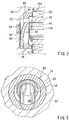
- Fig. 2 is a partially enlarged view of Fig. 1.
- Fig. 3 is a view of the cross-section along line III-III shown in Fig. 2
- Fig. 4 is a partial cross-section of a scroll compressor of a second representative embodiment.
-
- Representative scroll compressors are taught that may include, for example, a stationary scroll, a drive shaft member, a movable scroll, a bearing member, a compression chamber, a discharge port, a discharge valve and a discharge valve clamping device.
- The drive shaft member may revolve around a revolution axis. In other words, the drive shaft member may orbit around the center of the rotation. An offset drive shaft may preferably be utilized with a drive shaft to form a drive shaft member. The drive shaft member may drive the movable scroll. The bearing member is preferably disposed between the movable scroll and the drive shaft member in order to transmit the revolution of the drive shaft member around the revolution axis to the movable scroll. The compression chamber may be defined by a space formed between the stationary scroll and the movable scroll. The compression chamber compresses the fluid drawn into the compression chamber when the movable scroll revolves or orbits with respect to the stationary scroll.
- The discharge port is disposed within the movable scroll and is arranged and constructed to discharge the fluid within the compression chamber to the opposite side of the stationary scroll. The discharge valve may open and close the discharge port. The discharge valve clamping device is preferably affixed to the movable scroll. The discharge valve clamping device may prevent the discharge valve from moving together with the bearing member if the bearing member accidentally or unintentionally revolves together with the drive shaft member and independently from the movable scroll. The discharge valve clamping device may preferably comprise a clamping member. The clamping member may preferably clamp the discharge valve between the movable scroll and the bearing member. The clamping member may preferably be fixed to the movable scroll. By attaching the clamping member to the movable scroll, the clamping member will not transmit the rotation of the drive shaft member to the discharge valve. Preferably, the movable scroll may include a boss that extends toward the drive shaft member and the clamping member may be pressure-joined (e.g., frictionally fit) to the inner surface of the boss of the movable scroll. Further, the discharge valve clamping device may preferably be separated by a clearance from the bearing member in order to prevent the bearing member from transmitting its movement to the discharge valve.
- In another aspect of the present teachings, the discharge valve clamping device may preferably include a discharge valve clamping member and an engaging member. The discharge valve clamping member may extend between the bearing member and the discharge valve. Further, the engaging member may engage the discharge valve with the movable scroll such that the engaging member prevents the discharge valve from moving together with the rotation of the bearing member if the bearing member accidentally or unintentionally revolves or orbits together with the drive shaft member and independently from the movable scroll.
- Preferably, the engaging member may be defined by a concave-convex structure. The concave portion may preferably be provided on either of the movable scroll and the discharge valve. The convex portion joins with the concave portion-and may preferably be provided on the other of the movable scroll and the discharge valve.
- Each of the additional features and method steps disclosed above and below may be utilized separately or in conjunction with other features and method steps to provide improved scroll compressors and methods for designing and using such scroll compressors. Representative examples of the present invention, which examples utilize many of these additional features and method steps in conjunction, will now be described in detail with reference to the drawings. This detailed description is merely intended to teach a person of skill in the art further details for practicing preferred aspects of the present teachings and is not intended to limit the scope of the invention. Only the claims define the scope of the claimed invention. Therefore, combinations of features and steps disclosed in the following detail description may not be necessary to practice the invention in the broadest sense, and are instead taught merely to particularly describe some representative examples of the invention, which detailed description will now be given with reference to the accompanying drawings.
- A representative scroll compressor 1 is shown in Fig. 1 and may preferably be utilized within a refrigerant circulation circuit in a vehicle air-conditioning system. As shown in Fig. 1, the representative scroll compressor 1 includes a
housing 1a defined by a center housing 4, a motor housing 6 and anend housing 2a. Astationary scroll 2 is disposed within theend housing 2a. Amovable scroll 20 and other devices that drive themovable scroll 20 are also disposed within thehousing 1a. One end surface of the center housing 4 is coupled to theend housing 2a and another end surface of the center housing 4 is coupled to the motor housing 6. Adrive shaft 8 is rotatably supported byradial bearings crank shaft 14 is integrally coupled to the end of thedrive shaft 8. In the representative embodiments, thecrank shaft 14 and thedrive shaft 8 are one representative example of a drive shaft member according to the present teachings. - Two mutually parallel
planar portions 14a are formed on thecrank shaft 14. In Fig. 1, however, only oneplanar portion 14a is shown for the sake of convenience of explanation. Abush 16 is joined to thecrank shaft 14 by means of theplanar surfaces 14a so that thebush 16 may rotate together with thecrank shaft 14. A balancingweight 18 is attached to one end of thebush 16 so that the balancingweight 18 can rotate together with thecrank shaft 14. Themovable scroll 20 includes atubular boss 24a that is provided on the surface opposite to the stationary scroll 2 (on the right side of themovable scroll 20 in Fig. 1). Further, aneedle bearing 22 couples thebush 16 to the inner circumferential surface of theboss 24a to rotate relatively. Theneedle bearing 22 is one representative example of a "bearing member" as utilized in the present teachings. - The
stationary scroll 2 includes a stationary volute wall 28 that protrudes from abase plate 26 of thestationary scroll 2 towards themovable scroll 20. Themovable scroll 20 includes amovable volute wall 30 that protrudes from thebase plate 24 of themovable scroll 20 towards thestationary scroll 2. The stationary volute wall 28 and themovable volute wall 30 are disposed adjacent to each other and preferably aligned to engage or mesh with each other. Atip seal 28a is provided on the top end of the stationary volute wall 28 and atip seal 30a is provided on the top end of themovable volute wall 30. The volute walls are also known in the art as spiral wraps and these terms can be utilized interchangeably. - The stationary volute wall 28 and the
movable volute wall 30 make contact with each other at a plurality of positions and are positioned in meshing engagement. As the result, a plurality ofcompression chambers 32 with a crescent shape is defined within a space surrounded by the stationaryscroll base plate 26, the stationary volute wall 28, the movablescroll base plate 24 and themovable volute wall 30. When thedrive shaft 8 rotates, thecrank shaft 14 revolves or orbits around the rotational axis of thedrive shaft 8. The rotational axis may be defined as the center, longitudinal axis of thedrive shaft 8. Thus, the distance between thecrank shaft 14 and the rotational axis of thedrive shaft 8 defines the diameter of the orbital path. When themovable scroll 20 revolves or orbits about the rotational axis of thedrive shaft 8, the balancingweight 18 offsets the centrifugal force caused by the revolution of themovable scroll 20. - As shown in Figs. 2 and 3, a
discharge valve 52 is provided on the rear surface of the movable scroll base plate 24 (i.e., the surface facing the crank shaft 14). Adischarge port 50 is defined within the movablescroll base plate 24 and thedischarge valve 52 is disposed at thedischarge port 50 in order to open and close thedischarge port 50. Thedischarge valve 52 includes areed valve 54 and aretainer 56. Thereed valve 54 opens and closes thedischarge port 50 and preferably has an area or shape that is sufficient to cover the opening of thedischarge port 50. Theretainer 56 supports thereed valve 54. Thereed valve 54 and theretainer 56 are provided in avalve housing 25 formed in the rear surface of the movablescroll base plate 24. - The
reed valve 54 opens and closes based upon the pressure difference between the pressure within aspace 70 and the pressure within thedischarge port 50 orcompression chamber 32. Thereed valve 54 opens thedischarge port 50 when the pressure within thecompression chamber 32 is greater than the pressure within thespace 70. Thereed valve 54 closes thedischarge port 50 when the pressure within thecompression chamber 32 is lower than the pressure within thespace 70. Theretainer 56 supports thereed valve 54 and also defines the maximum aperture of thereed valve 54. - A discharge
valve clamping ring 60 is provided within thevalve housing 25. The dischargevalve clamping ring 60 is pressure-joined (i.e., frictionally fitted) to the inner circumferential surface of theboss 24a and is thus integrated with themovable scroll 20. Thereed valve 54 and theretainer 56 are clamped or secured between the dischargevalve clamping ring 60 and the movablescroll base plate 24. This pressure-joined dischargevalve clamping ring 60 is one representative example of a "discharge valve clamping device" and "means for preventing the discharge valve from rotating" according to the present teachings. By pressure-joining the dischargevalve clamping ring 60 to the inner circumferential surface of theboss 24a, thedischarge valve 52 can be prevented from moving together with theneedle bearing 22 if theneedle bearing 22 accidentally or unintentionally revolves together with thecrank shaft 14 and independent from themovable scroll 20. As the result, the positional relationship between thedischarge valve 52 and thedischarge port 50 can be reliably maintained. As shown in Fig. 2, a small clearance "t" separates the dischargevalve clamping ring 60 from theend 22a of theneedle bearing 22. Thus, theneedle bearing 22 can not transmit rotational movement to the dischargevalve clamping ring 60 due to the clearance "t" that separates the dischargevalve clamping ring 60 from theneedle bearing 22 by. - As shown in Fig. 1, an
orbiting ring 34 is disposed between thebase plate 24 of themovable scroll 20 and the center housing 4. The orbitingring 34 includes auto-rotation preventing pins 36 that penetrate toward themovable scroll 20. In this embodiment, a total of four auto-rotation preventing pins 36 are provided. However, only two auto-rotation preventing pins 36 are shown in Fig. 1. A bearingplate 38 is provided between the center housing 4 and theorbiting ring 34. The auto-rotation preventing pins 36 and auto-rotation preventing holes 40 are circumferentially aligned within the bearingplate 38. Thus, each auto-rotation preventing pin 36 respectively engages with an auto-rotation preventing hole 40 defined within the bearingplate 38. Further, each auto-rotation preventing pin 36 respectively engages with an auto-rotation preventing hole 42 defined withinbase plate 24 of themovable scroll 20. The end portion of the auto-rotation preventing pin 36 is inserted into each corresponding auto-rotation preventing holes - A
stator 46 is provided on the inner circumferential surface of the motor housing 6. Further, arotor 48 is coupled to thedrive shaft 8. Thestator 46 and therotor 48 define an electric motor that rotates thedrive shaft 8. Thus, the present scroll compressors are particularly useful for hybrid or electric cars that operate using electric power. However, an electric motor is not essential to the present teachings and the present scroll compressor can be easily modified for use with internal combustion engines. - When the
drive shaft 8 rotates together with thecrank shaft 14, thecrank shaft 14 revolves (orbits) around the rotational axis of thedrive shaft 8. Also, thecrank shaft 14 rotates around its auto-rotating axis (which is same as the rotational axis of the crank shaft 14). However, the auto-rotation preventing pin 36 only permits themovable scroll 20 to receive the orbital movement of thecrank shaft 14 by means of theneedle bearing 22. Further, the auto-rotation of thecrank shaft 14 will not be transmitted to the movable scroll due to the auto-rotation preventing pin 36. As a result of the orbital movement of themovable scroll 20 with respect to thestationary scroll 2, refrigerant gas (fluid) is drawn from asuction port 44 and closed into thecompression chamber 32, which is defined between thestationary scroll 2 and themovable scroll 20. In conjunction with the revolution of themovable scroll 20, the surface of the auto-rotation preventing pin 36 slides along the surface of the respective auto-rotation preventing holes rotation preventing holes rotation preventing pins 36, and the revolutionary (orbital) radius "r" of thebush 16 are preferably defined in a relationship such as "D=d+r". Due to this relationship, the revolutionary (orbital) radius of themovable scroll 20 is defined by "r", and theorbiting ring 34 revolves at a radius that is one-half of the revolutionary radius "r" of themovable scroll 20. - While the
crank shaft 14 revolves, the orbitingring 34 is prevented from auto-rotating because the inner circumferences of the auto-rotation preventing holes 40 contact the auto-rotation preventing pins 36 on theorbiting ring 34. Further, themovable scroll 20 is prevented from auto-rotating around the central axis of thebush 16 because the inner circumferences of the auto-rotation preventing holes 42 are in contact with the auto-rotation preventing pins 36 on theorbiting ring 34. - When the
crank shaft 14 revolves, themovable scroll 20 connected to thecrank shaft 14 by means of theneedle bearing 22 orbits or revolves along a circular path. When themovable scroll 20 revolves or orbits with respect to thestationary scroll 2, the refrigerant gas (fluid) is drawn from thesuction port 44 and is closed into thecompression chamber 32 and thecompression chamber 32 reduces its volume as thecompression chamber 32 moves toward the center of the stationary andmovable scrolls compression chamber 32, the refrigerant gas is compressed and reaches a high pressure state. - The compressed high-pressure refrigerant gas is discharged from the
discharge port 50 to the high-pressure chamber 53 when thedischarge valve 52 opens thedischarge port 50. Thespace 70 communicates with the interior of the motor housing 6 via apassage 72 formed inside thecrank shaft 14 and thedrive shaft 8. Further, the refrigerant gas introduced into the motor housing 6 is discharged from thepassage 74 provided in thedrive shaft 8 to an external air conditioning circuit via anoutlet 76 formed in a wall portion of the motor housing 6. Because the refrigerant gas is communicated through the interior of the motor housing 6, the refrigerant gas can cool the electric motor (i.e.rotor 48 and stator 46) during operation. - According to the representative scroll compressor 1, the discharge
valve clamping ring 60 that clamps thedischarge valve 52 is pressure-joined (i.e., frictionally fitted) onto themovable scroll 20. Thus, thedischarge valve 52 is prevented from moving together with theneedle bearing 22 even if theneedle bearing 22 accidentally or unintentionally revolves independently from themovable scroll 20. In other words, the movement of theneedle bearing 22 can be stopped or prevented from being transmitted to the dischargevalve clamping ring 60. Further, the dischargevalve clamping ring 60 can be pressure-joined to themovable scroll 20 without requiring any special means, such as a bolt, in order to couple or affix the dischargevalve clamping ring 60 to themovable scroll 20. - A second representative embodiment is shown in Fig. 4, which shows a partial cross-section of the
scroll compressor 100. Because a substantial portion of the elements of thescroll compressor 100 are similar to the elements described with respect to the scroll compressor 1 according to the first representative embodiment, only the elements differing from the first representative embodiment will be described. Further, elements that are substantially identical to the corresponding elements of the first representative embodiment are identified in Fig. 4 with the same reference numbers that were utilized in Fig. 2. - As shown in Fig. 4, a
positioning groove 25a is defined in the movablescroll base plate 24. Apositioning protrusion 56a is defined on theretainer 56 and is coupled to thepositioning groove 25a. Preferably, thepositioning protrusion 56 may be pressure-joined (i.e. frictionally fitted) into thepositioning groove 25a. By coupling thepositioning protrusion 56a to thepositioning groove 25a, thereed valve 54 and theretainer 56 can be accurately positioned with respect to the movablescroll base plate 24. In other words, it becomes relatively simple to position the discharge valve when installing thepositioning protrusion 56a in thepositioning groove 25a. - A ring-shaped discharge
valve clamping ring 62 is disposed between thedischarge valve 52 and theneedle bearing 22. Thereed valve 54 and theretainer 56 are clamped or secured between the movablescroll base plate 24 and the dischargevalve clamping ring 62. The dischargevalve clamping ring 62 contacts theend portion 22a of theneedle bearing 22. That is, thedischarge valve 52 is pressed against the movablescroll base plate 24 by theneedle bearing 22 via the dischargevalve clamping ring 62. As a result, the dischargevalve clamping ring 62 may possibly revolve in accordance with the revolution of theneedle bearing 22 and independent from themovable scroll 20. - However, because the
positioning protrusion 56a is coupled to thepositioning groove 25a, thedischarge valve 52 can be prevented from moving together with theneedle bearing 22 even if theneedle bearing 22 causes the dischargevalve clamping ring 62 to unintentionally revolve independently from themovable scroll 20. In other words, the joining force between the positioninggroove 25a and thepositioning protrusion 56a can effectively resist the rotational force of theneedle bearing 22. - The invention is not restricted to the above described representative embodiments and various modifications may be made to the representative embodiments without departing from the present teachings.
- For example, the
discharge valve 52 may be prevented from moving together with theneedle bearing 22 by utilizing both dischargevalve clamping ring 60 fixed to the inner surface of theboss 24a of themovable scroll 20 and thepositioning protrusion 56a engaged with thepositioning groove 25a. - In the second representative embodiment, the discharge
valve clamping ring 62 is sandwiched or interleaved between thedischarge valve 52 and theneedle bearing 22. However, the discharge valve clamping ring can be omitted. Further, thedischarge valve 52 may be clamped by the end portion of theneedle bearing 22. In this modification, thedischarge valve 52 can be prevented from moving with theneedle bearing 22 by means of the joining force between the positioninggroove 25a and thepositioning protrusion 56a when the rotational force of theneedle bearing 22 acts on thedischarge valve 52. Further, the bearing member is not limited to the needle bearing and may be selected from various types of bearings in accordance with the design requirements of the particular scroll compressor. - In the second preferred embodiment, the
positioning groove 25a is provided on the movablescroll base plate 24 and thepositioning protrusion 56a is provided on theretainer 56. However, thepositioning groove 25a may be provided on theretainer 56 and thepositioning protrusion 56a may be provided on the movablescroll base plate 24.
Claims (16)
- A scroll compressor comprising:characterized by a discharge valve clamping device affixed to the movable scroll, wherein the discharge valve clamping device prevents the discharge valve from moving together with the bearing member.a stationary scroll,a drive shaft member having a rotational axis,a movable scroll driven by the drive shaft member, the movable scroll disposed adjacent to the stationary scroll,a bearing member disposed between the movable scroll and the drive shaft member and arranged and constructed to transmit rotational movement of the drive shaft member about the rotational axis to the movable scroll,a compression chamber defined by a space between the stationary scroll and the movable scroll, wherein fluid is compressed within the compression chamber when the movable scroll revolves or orbits with respect to the stationary scroll,a discharge port defined within the movable scroll and adapted to discharge the compressed fluid to a side that is opposite of the stationary scroll, anda discharge valve coupled to the discharge port and operable to open and close the discharge port,
- A scroll compressor according to claim 1, wherein the discharge valve clamping device comprises a clamping member that is arranged and constructed to clamp the discharge valve between the movable scroll and the clamping member.
- A scroll compressor according to claim 2, wherein the movable scroll includes a boss that extends in the axial direction of the drive shaft member and the clamping member is pressure-joined to the inner surface of the boss of the movable scroll.
- A scroll compressor according to any one of claims 1 to 3, wherein a clearance separates the discharge valve clamping device from the bearing member.
- A scroll compressor according to any one of claims 1 to 4, further comprising an electric motor disposed within a motor housing, wherein the motor housing is in communication with the discharge port, the electric motor is coupled to and drives the drive shaft member and wherein compressed fluid from the compression chamber is introduced into the motor housing via the discharge port in order to cool the electric motor during operation.
- A scroll compressor comprising:characterized by a discharge valve clamping device comprising a discharge valve clamping member and an engaging member, wherein the discharge valve clamping member clamps the discharge valve between the movable scroll and the discharge valve clamping member, the engaging member engages the discharge valve with the movable scroll such that the engaging member prevents the discharge valve from moving together with the bearing member if the bearing member accidentally revolves together with the drive shaft member and independently from the movable scroll.a stationary scroll,a drive shaft member adapted to rotate about a revolution axis,a movable scroll driven by the drive shaft member,a bearing member disposed between the movable scroll and the drive shaft member and arranged and constructed to transmit revolution of the drive shaft member about the revolution axis to the movable scroll,a compression chamber defined by a space between the stationary scroll and the movable scroll, wherein fluid is compressed in the compression chamber when the movable scroll revolves or orbits with respect to the stationary scroll,a discharge port defined within the movable scroll and adapted to discharge fluid within the compression chamber to the opposite side of the stationary scroll,a discharge valve arranged and constructed to open and close the discharge port,
- A scroll compressor according to claim 6, wherein the engaging member comprises a concave-convex structure, wherein the concave portion is provided on one of the movable scroll and the discharge valve and the convex portion is provided on the other of the movable scroll and the discharge valve, wherein the concave portion joins with the convex portion.
- A scroll compressor according to claim 7, wherein the concave-convex structure positions the discharge valve with respect to the movable scroll.
- A scroll compressor comprising:characterized by means for preventing the discharge valve from moving together with the bearing member if the bearing member accidentally or unintentionally revolves together with the drive shaft member and independently from the movable scroll.a stationary scroll,a drive shaft member having a rotational axis,a movable scroll driven by the drive shaft member, the movable scroll disposed adjacent to the stationary scroll,a bearing member disposed between the movable scroll and the drive shaft member and arranged and constructed to transmit rotational movement of the drive shaft member about the rotational axis to the movable scroll,a compression chamber defined by a space between the stationary scroll and the movable scroll, wherein fluid is compressed within the compression chamber when the movable scroll revolves or orbits with respect to the stationary scroll,a discharge port defined within the movable scroll and adapted to discharge the compressed fluid to a side that is opposite of the stationary scroll, anda discharge valve coupled to the discharge port and operable to open and close the discharge port,
- A scroll compressor comprising:characterized by means for clamping the discharge valve to prevent the discharge valve from moving together with the bearing member if the bearing member accidentally or unintentionally revolves together with the drive shaft member and independently from the movable scroll.a stationary scroll,a drive shaft member having a rotational axis,a movable scroll driven by the drive shaft member, the movable scroll disposed adjacent to the stationary scroll,a bearing member disposed between the movable scroll and the drive shaft member and arranged and constructed to transmit rotational movement of the drive shaft member about the rotational axis to the movable scroll,a compression chamber defined by a space between the stationary scroll and the movable scroll, wherein fluid is compressed within the compression chamber when the movable scroll revolves or orbits with respect to the stationary scroll,a discharge port defined within the movable scroll and adapted to discharge the compressed fluid to a side that is opposite of the stationary scroll, anda discharge valve coupled to the discharge port and operable to open and close the discharge port,
- A scroll compressor comprising:characterized by a discharge valve clamping device affixed to the movable scroll, wherein the discharge valve clamping device prevents the discharge valve from moving together with the bearing member if the bearing member unintentionally revolves together with the drive shaft member and independent from the movable scroll, the discharge valve clamping device comprising a clamping member that clamps the discharge valve between the movable scroll and the clamping member, wherein the clamping member is pressure-joined to the inner surface of the boss of the movable scroll.a stationary scroll,a drive shaft member having a rotational axis,a movable scroll driven by the drive shaft member, the movable scroll disposed adjacent to the stationary scroll,a bearing member disposed between the movable scroll and the drive shaft member and arranged and constructed to transmit rotational movement of the drive shaft member about the rotational axis to the movable scroll,a compression chamber defined by a space between the stationary scroll and the movable scroll, wherein fluid is compressed within the compression chamber when the movable scroll revolves or orbits with respect to the stationary scroll,a discharge port defined within the movable scroll and adapted to discharge the compressed fluid to a side that is opposite of the stationary scroll, anda discharge valve coupled to the discharge port and operable to open and close the discharge port,
- A scroll compressor comprising:characterized by a discharge valve clamping device fixed to the movable scroll, wherein the discharge valve clamping device prevents the discharge valve from moving together with the bearing member when the bearing member accidentally revolves together with the drive shaft member independent from the movable scroll, the discharge valve clamping device is separated by a clearance from the bearing member.a stationary scroll,a drive shaft member that revolves around a revolution axis,a movable scroll driven by the drive shaft member,a bearing member provided between the movable scroll and the drive shaft member to transmit the revolution of the drive shaft member around the revolution axis,a compression chamber defined by a space between the stationary scroll and the movable scroll, wherein fluid is compressed in the compression chamber when the movable scroll revolves with respect to the stationary scroll,a discharge port disposed at the movable scroll to discharge the fluid within the compression chamber to the opposite side of the stationary scroll,a discharge valve that opens and closes the discharge port,
- A scroll compressor comprising:characterized by a discharge valve clamping device that includes a discharge valve clamping member and an engaging member, wherein the discharge valve clamping member clamps the discharge valve between the movable scroll and the discharge valve clamping member, the engaging member engages the discharge valve with the movable scroll such that the engaging member prevents the discharge valve from moving together with the bearing member when the bearing member accidentally revolves together with the drive shaft member independent from the movable scroll, the engaging member is defined by a concave-convex structure, the concave portion is provided on anyone of the movable scroll and the discharge valve, the convex portion to join the concave portion is provided on the another of the movable scroll and the discharge valve.a stationary scroll,a drive shaft member that revolves around a revolution axis,a movable scroll driven by the drive shaft member,a bearing member provided between the movable scroll and the drive shaft member to transmit the revolution of the drive shaft member around the revolution axis,a compression chamber defined by a space between the stationary scroll and the movable scroll, wherein fluid is compressed in the compression chamber when the movable scroll revolves with respect to the stationary scroll,a discharge port disposed at the movable scroll to discharge the fluid within the compression chamber to the opposite side of the stationary scroll,a discharge valve that opens and closes the discharge port,
- A scroll compressor according to any one of claims 1 to 14, wherein the drive shaft member is defined by a drive shaft and a crank shaft.
- A scroll compressor according to any one of claims 1 to 14, wherein the bearing member is defined by a plain bearing.
- A scroll compressor according to claim 7 or 8, wherein the discharge valve includes a retainer, one of the concave and convex portions is provided with the retainer.
Applications Claiming Priority (2)
| Application Number | Priority Date | Filing Date | Title |
|---|---|---|---|
| JP2000280457 | 2000-09-14 | ||
| JP2000280457A JP2002089468A (en) | 2000-09-14 | 2000-09-14 | Scroll type compressor |
Publications (1)
| Publication Number | Publication Date |
|---|---|
| EP1188929A1 true EP1188929A1 (en) | 2002-03-20 |
Family
ID=18765289
Family Applications (1)
| Application Number | Title | Priority Date | Filing Date |
|---|---|---|---|
| EP01121681A Withdrawn EP1188929A1 (en) | 2000-09-14 | 2001-09-14 | Scroll compressors |
Country Status (3)
| Country | Link |
|---|---|
| US (1) | US6544016B2 (en) |
| EP (1) | EP1188929A1 (en) |
| JP (1) | JP2002089468A (en) |
Families Citing this family (37)
| Publication number | Priority date | Publication date | Assignee | Title |
|---|---|---|---|---|
| US7261527B2 (en) * | 2004-04-19 | 2007-08-28 | Scroll Technologies | Compressor check valve retainer |
| JP2006329156A (en) * | 2005-05-30 | 2006-12-07 | Daikin Ind Ltd | Rotary compressor |
| US7976295B2 (en) | 2008-05-30 | 2011-07-12 | Emerson Climate Technologies, Inc. | Compressor having capacity modulation system |
| CN102418698B (en) | 2008-05-30 | 2014-12-10 | 艾默生环境优化技术有限公司 | Compressor having output adjustment assembly including piston actuation |
| KR101280915B1 (en) * | 2008-05-30 | 2013-07-02 | 에머슨 클리메이트 테크놀로지즈 인코퍼레이티드 | Compressor having capacity modulation system |
| US7988433B2 (en) | 2009-04-07 | 2011-08-02 | Emerson Climate Technologies, Inc. | Compressor having capacity modulation assembly |
| US8568118B2 (en) * | 2009-05-29 | 2013-10-29 | Emerson Climate Technologies, Inc. | Compressor having piston assembly |
| US8616014B2 (en) | 2009-05-29 | 2013-12-31 | Emerson Climate Technologies, Inc. | Compressor having capacity modulation or fluid injection systems |
| US8517703B2 (en) * | 2010-02-23 | 2013-08-27 | Emerson Climate Technologies, Inc. | Compressor including valve assembly |
| US9267501B2 (en) | 2011-09-22 | 2016-02-23 | Emerson Climate Technologies, Inc. | Compressor including biasing passage located relative to bypass porting |
| JP5921408B2 (en) * | 2012-10-16 | 2016-05-24 | 三菱電機株式会社 | Discharge valve device and scroll compressor provided with the same |
| US9651043B2 (en) | 2012-11-15 | 2017-05-16 | Emerson Climate Technologies, Inc. | Compressor valve system and assembly |
| US9249802B2 (en) | 2012-11-15 | 2016-02-02 | Emerson Climate Technologies, Inc. | Compressor |
| US9435340B2 (en) | 2012-11-30 | 2016-09-06 | Emerson Climate Technologies, Inc. | Scroll compressor with variable volume ratio port in orbiting scroll |
| US9127677B2 (en) | 2012-11-30 | 2015-09-08 | Emerson Climate Technologies, Inc. | Compressor with capacity modulation and variable volume ratio |
| US20140271302A1 (en) | 2013-03-18 | 2014-09-18 | Suchul Kim | Scroll compressor with a bypass |
| JP6040912B2 (en) * | 2013-11-12 | 2016-12-07 | 株式会社デンソー | High pressure pump |
| US9739277B2 (en) | 2014-05-15 | 2017-08-22 | Emerson Climate Technologies, Inc. | Capacity-modulated scroll compressor |
| US9989057B2 (en) | 2014-06-03 | 2018-06-05 | Emerson Climate Technologies, Inc. | Variable volume ratio scroll compressor |
| US9790940B2 (en) | 2015-03-19 | 2017-10-17 | Emerson Climate Technologies, Inc. | Variable volume ratio compressor |
| US10378540B2 (en) | 2015-07-01 | 2019-08-13 | Emerson Climate Technologies, Inc. | Compressor with thermally-responsive modulation system |
| CN207377799U (en) | 2015-10-29 | 2018-05-18 | 艾默生环境优化技术有限公司 | Compressor |
| WO2017138098A1 (en) * | 2016-02-09 | 2017-08-17 | 三菱電機株式会社 | Scroll compressor |
| US10890186B2 (en) | 2016-09-08 | 2021-01-12 | Emerson Climate Technologies, Inc. | Compressor |
| US10801495B2 (en) | 2016-09-08 | 2020-10-13 | Emerson Climate Technologies, Inc. | Oil flow through the bearings of a scroll compressor |
| US10753352B2 (en) * | 2017-02-07 | 2020-08-25 | Emerson Climate Technologies, Inc. | Compressor discharge valve assembly |
| US11022119B2 (en) | 2017-10-03 | 2021-06-01 | Emerson Climate Technologies, Inc. | Variable volume ratio compressor |
| US10962008B2 (en) | 2017-12-15 | 2021-03-30 | Emerson Climate Technologies, Inc. | Variable volume ratio compressor |
| US10995753B2 (en) | 2018-05-17 | 2021-05-04 | Emerson Climate Technologies, Inc. | Compressor having capacity modulation assembly |
| US11656003B2 (en) | 2019-03-11 | 2023-05-23 | Emerson Climate Technologies, Inc. | Climate-control system having valve assembly |
| US11655813B2 (en) | 2021-07-29 | 2023-05-23 | Emerson Climate Technologies, Inc. | Compressor modulation system with multi-way valve |
| US12259163B2 (en) | 2022-06-01 | 2025-03-25 | Copeland Lp | Climate-control system with thermal storage |
| US11846287B1 (en) | 2022-08-11 | 2023-12-19 | Copeland Lp | Scroll compressor with center hub |
| US11965507B1 (en) | 2022-12-15 | 2024-04-23 | Copeland Lp | Compressor and valve assembly |
| US12416308B2 (en) | 2022-12-28 | 2025-09-16 | Copeland Lp | Compressor with shutdown assembly |
| US12173708B1 (en) | 2023-12-07 | 2024-12-24 | Copeland Lp | Heat pump systems with capacity modulation |
| US12163523B1 (en) | 2023-12-15 | 2024-12-10 | Copeland Lp | Compressor and valve assembly |
Citations (5)
| Publication number | Priority date | Publication date | Assignee | Title |
|---|---|---|---|---|
| US4369808A (en) * | 1981-01-22 | 1983-01-25 | Hagman Emanuel F | Disc-type check valve |
| WO1989005918A1 (en) * | 1987-12-23 | 1989-06-29 | 3H Invent A/S | Valve arrangement for pump or compressor |
| JPH02227583A (en) * | 1989-02-28 | 1990-09-10 | Toshiba Corp | Scroll compressor |
| JPH06264875A (en) * | 1993-03-10 | 1994-09-20 | Toyota Autom Loom Works Ltd | Scroll compressor |
| EP1039136A2 (en) * | 1999-03-23 | 2000-09-27 | Copeland Corporation | Scroll machine with discharge valve |
Family Cites Families (4)
| Publication number | Priority date | Publication date | Assignee | Title |
|---|---|---|---|---|
| JPH06235385A (en) * | 1993-02-09 | 1994-08-23 | Toyota Autom Loom Works Ltd | Scroll type compressor |
| JPH06280757A (en) | 1993-03-30 | 1994-10-04 | Toyota Autom Loom Works Ltd | Scroll type compressor |
| JP3031297B2 (en) | 1997-06-12 | 2000-04-10 | ダイキン工業株式会社 | Scroll compressor |
| JP2000220584A (en) * | 1999-02-02 | 2000-08-08 | Toyota Autom Loom Works Ltd | Scroll type compressor |
-
2000
- 2000-09-14 JP JP2000280457A patent/JP2002089468A/en active Pending
-
2001
- 2001-09-13 US US09/952,287 patent/US6544016B2/en not_active Expired - Fee Related
- 2001-09-14 EP EP01121681A patent/EP1188929A1/en not_active Withdrawn
Patent Citations (5)
| Publication number | Priority date | Publication date | Assignee | Title |
|---|---|---|---|---|
| US4369808A (en) * | 1981-01-22 | 1983-01-25 | Hagman Emanuel F | Disc-type check valve |
| WO1989005918A1 (en) * | 1987-12-23 | 1989-06-29 | 3H Invent A/S | Valve arrangement for pump or compressor |
| JPH02227583A (en) * | 1989-02-28 | 1990-09-10 | Toshiba Corp | Scroll compressor |
| JPH06264875A (en) * | 1993-03-10 | 1994-09-20 | Toyota Autom Loom Works Ltd | Scroll compressor |
| EP1039136A2 (en) * | 1999-03-23 | 2000-09-27 | Copeland Corporation | Scroll machine with discharge valve |
Non-Patent Citations (2)
| Title |
|---|
| PATENT ABSTRACTS OF JAPAN vol. 014, no. 540 (M - 1053) 29 November 1990 (1990-11-29) * |
| PATENT ABSTRACTS OF JAPAN vol. 018, no. 671 (M - 1726) 19 December 1994 (1994-12-19) * |
Also Published As
| Publication number | Publication date |
|---|---|
| US6544016B2 (en) | 2003-04-08 |
| JP2002089468A (en) | 2002-03-27 |
| US20030044297A1 (en) | 2003-03-06 |
Similar Documents
| Publication | Publication Date | Title |
|---|---|---|
| US6544016B2 (en) | Scroll compressors | |
| EP1188928B1 (en) | Scroll compressors | |
| EP1188927B1 (en) | Scroll compressors | |
| US6454551B2 (en) | Seal structure in a scroll type compressor | |
| US6464481B2 (en) | Scroll compressors | |
| CN114729637B (en) | Co-rotating scroll compressor | |
| EP0066457A2 (en) | Driving support mechanism for an orbiting scroll of a scroll type fluid displacement apparatus | |
| EP0106288B1 (en) | Scroll type compressor | |
| CN112443484B (en) | Electric compressor | |
| US5540571A (en) | Scroll-type compressor having bolted housings | |
| EP0078128B1 (en) | A drive bearing device for a fluid displacement apparatus | |
| US4477239A (en) | Scroll type fluid displacement apparatus with offset wraps for reduced housing diameter | |
| CN116097001B (en) | Compressor and method for manufacturing compressor | |
| US5738504A (en) | Rotation preventing device for orbiting member of fluid displacement apparatus | |
| JP4153131B2 (en) | Electric compressor | |
| US12607186B2 (en) | Co-rotating scroll compressor | |
| CN116568929B (en) | Scroll compressor having a rotor with a rotor shaft having a rotor shaft with a | |
| US5702241A (en) | Scroll-type fluid displacement apparatus having sealing means for central portions of the wraps | |
| KR100223439B1 (en) | Scroll compressor | |
| US12473917B2 (en) | Scroll assemblies and compressors including the same | |
| EP0070617A2 (en) | Scroll type fluid displacement apparatus | |
| US6382941B1 (en) | Device and method to prevent misbuild and improper function of air conditioning scroll compressor due to misplaced or extra steel spherical balls | |
| EP0240739B1 (en) | Scroll type compressor with lubricating system | |
| JPH0727061A (en) | Scroll compressor | |
| CN120112721A (en) | Twin-rotary scroll compressor |
Legal Events
| Date | Code | Title | Description |
|---|---|---|---|
| PUAI | Public reference made under article 153(3) epc to a published international application that has entered the european phase |
Free format text: ORIGINAL CODE: 0009012 |
|
| 17P | Request for examination filed |
Effective date: 20010914 |
|
| AK | Designated contracting states |
Kind code of ref document: A1 Designated state(s): AT BE CH CY DE DK ES FI FR GB GR IE IT LI LU MC NL PT SE TR Kind code of ref document: A1 Designated state(s): DE IT PT |
|
| AX | Request for extension of the european patent |
Free format text: AL;LT;LV;MK;RO;SI |
|
| AKX | Designation fees paid |
Free format text: DE IT PT |
|
| 17Q | First examination report despatched |
Effective date: 20030903 |
|
| STAA | Information on the status of an ep patent application or granted ep patent |
Free format text: STATUS: THE APPLICATION IS DEEMED TO BE WITHDRAWN |
|
| 18D | Application deemed to be withdrawn |
Effective date: 20070331 |