EP1188641A2 - Axle assembly and tractor comprising an axle assembly - Google Patents
Axle assembly and tractor comprising an axle assembly Download PDFInfo
- Publication number
- EP1188641A2 EP1188641A2 EP01120830A EP01120830A EP1188641A2 EP 1188641 A2 EP1188641 A2 EP 1188641A2 EP 01120830 A EP01120830 A EP 01120830A EP 01120830 A EP01120830 A EP 01120830A EP 1188641 A2 EP1188641 A2 EP 1188641A2
- Authority
- EP
- European Patent Office
- Prior art keywords
- ball
- stud
- steering
- axle assembly
- knuckle
- Prior art date
- Legal status (The legal status is an assumption and is not a legal conclusion. Google has not performed a legal analysis and makes no representation as to the accuracy of the status listed.)
- Granted
Links
Images


Classifications
-
- B—PERFORMING OPERATIONS; TRANSPORTING
- B60—VEHICLES IN GENERAL
- B60G—VEHICLE SUSPENSION ARRANGEMENTS
- B60G3/00—Resilient suspensions for a single wheel
- B60G3/18—Resilient suspensions for a single wheel with two or more pivoted arms, e.g. parallelogram
- B60G3/20—Resilient suspensions for a single wheel with two or more pivoted arms, e.g. parallelogram all arms being rigid
-
- B—PERFORMING OPERATIONS; TRANSPORTING
- B60—VEHICLES IN GENERAL
- B60G—VEHICLE SUSPENSION ARRANGEMENTS
- B60G7/00—Pivoted suspension arms; Accessories thereof
- B60G7/02—Attaching arms to sprung part of vehicle
-
- B—PERFORMING OPERATIONS; TRANSPORTING
- B62—LAND VEHICLES FOR TRAVELLING OTHERWISE THAN ON RAILS
- B62D—MOTOR VEHICLES; TRAILERS
- B62D7/00—Steering linkage; Stub axles or their mountings
- B62D7/18—Steering knuckles; King pins
-
- B—PERFORMING OPERATIONS; TRANSPORTING
- B60—VEHICLES IN GENERAL
- B60G—VEHICLE SUSPENSION ARRANGEMENTS
- B60G2200/00—Indexing codes relating to suspension types
- B60G2200/10—Independent suspensions
- B60G2200/14—Independent suspensions with lateral arms
- B60G2200/144—Independent suspensions with lateral arms with two lateral arms forming a parallelogram
-
- B—PERFORMING OPERATIONS; TRANSPORTING
- B60—VEHICLES IN GENERAL
- B60G—VEHICLE SUSPENSION ARRANGEMENTS
- B60G2200/00—Indexing codes relating to suspension types
- B60G2200/40—Indexing codes relating to the wheels in the suspensions
- B60G2200/422—Driving wheels or live axles
-
- B—PERFORMING OPERATIONS; TRANSPORTING
- B60—VEHICLES IN GENERAL
- B60G—VEHICLE SUSPENSION ARRANGEMENTS
- B60G2200/00—Indexing codes relating to suspension types
- B60G2200/40—Indexing codes relating to the wheels in the suspensions
- B60G2200/44—Indexing codes relating to the wheels in the suspensions steerable
-
- B—PERFORMING OPERATIONS; TRANSPORTING
- B60—VEHICLES IN GENERAL
- B60G—VEHICLE SUSPENSION ARRANGEMENTS
- B60G2204/00—Indexing codes related to suspensions per se or to auxiliary parts
- B60G2204/10—Mounting of suspension elements
- B60G2204/14—Mounting of suspension arms
- B60G2204/143—Mounting of suspension arms on the vehicle body or chassis
-
- B—PERFORMING OPERATIONS; TRANSPORTING
- B60—VEHICLES IN GENERAL
- B60G—VEHICLE SUSPENSION ARRANGEMENTS
- B60G2204/00—Indexing codes related to suspensions per se or to auxiliary parts
- B60G2204/10—Mounting of suspension elements
- B60G2204/14—Mounting of suspension arms
- B60G2204/147—Mounting of suspension arms on the vehicle engine body
-
- B—PERFORMING OPERATIONS; TRANSPORTING
- B60—VEHICLES IN GENERAL
- B60G—VEHICLE SUSPENSION ARRANGEMENTS
- B60G2204/00—Indexing codes related to suspensions per se or to auxiliary parts
- B60G2204/10—Mounting of suspension elements
- B60G2204/14—Mounting of suspension arms
- B60G2204/148—Mounting of suspension arms on the unsprung part of the vehicle, e.g. wheel knuckle or rigid axle
-
- B—PERFORMING OPERATIONS; TRANSPORTING
- B60—VEHICLES IN GENERAL
- B60G—VEHICLE SUSPENSION ARRANGEMENTS
- B60G2204/00—Indexing codes related to suspensions per se or to auxiliary parts
- B60G2204/40—Auxiliary suspension parts; Adjustment of suspensions
- B60G2204/416—Ball or spherical joints
-
- B—PERFORMING OPERATIONS; TRANSPORTING
- B60—VEHICLES IN GENERAL
- B60G—VEHICLE SUSPENSION ARRANGEMENTS
- B60G2206/00—Indexing codes related to the manufacturing of suspensions: constructional features, the materials used, procedures or tools
- B60G2206/01—Constructional features of suspension elements, e.g. arms, dampers, springs
- B60G2206/50—Constructional features of wheel supports or knuckles, e.g. steering knuckles, spindle attachments
-
- B—PERFORMING OPERATIONS; TRANSPORTING
- B60—VEHICLES IN GENERAL
- B60G—VEHICLE SUSPENSION ARRANGEMENTS
- B60G2300/00—Indexing codes relating to the type of vehicle
- B60G2300/08—Agricultural vehicles
- B60G2300/082—Tractors
-
- Y—GENERAL TAGGING OF NEW TECHNOLOGICAL DEVELOPMENTS; GENERAL TAGGING OF CROSS-SECTIONAL TECHNOLOGIES SPANNING OVER SEVERAL SECTIONS OF THE IPC; TECHNICAL SUBJECTS COVERED BY FORMER USPC CROSS-REFERENCE ART COLLECTIONS [XRACs] AND DIGESTS
- Y10—TECHNICAL SUBJECTS COVERED BY FORMER USPC
- Y10T—TECHNICAL SUBJECTS COVERED BY FORMER US CLASSIFICATION
- Y10T403/00—Joints and connections
- Y10T403/32—Articulated members
- Y10T403/32606—Pivoted
- Y10T403/32631—Universal ball and socket
Definitions
- the present invention relates to an axle assembly and a tractor with an axle assembly having a steering knuckle and a ball joint assembly.
- a front suspension provides improved operator comfort, thereby reducing operator fatigue.
- the tractor frame is subject to less impact loading during operation.
- a front suspension axle adds complexity and additional components to the front axle.
- front wheel drive To further improve the performance of agricultural tractors, many tractors are provided with front wheel drive. While the front wheels and tires are typically smaller than the rear, by driving both the rear and the front wheels, tractive efficiency is improved.
- a mechanical front wheel drive requires a front drive axle with considerably more components compared to a front axle without mechanical front wheel drive.
- the ball joint utilizes a ball stud having a spherical ball portion and a pair of studs extending oppositely therefrom for attachment to the steering knuckle.
- the double studded ball stud enables the overall size of the ball studs to be reduced compared to a ball stud having a single stud.
- One stud of the ball stud is press fit into the steering knuckle while the other stud is captured in a cap that is secured to the knuckle by threaded fasteners.
- the cap clamps to the stud to securely retain the ball stud.
- Dowels extend through mounting apertures in the cap and into the steering knuckle to increase the shear strength of the attachment beyond that provided solely by the threaded fasteners themselves. The result is a high strength yet relatively compact ball joint design resulting in a joint that does not interfere with the packaging space required for suspension, powertrain and steering components at the front axle.
- the steering knuckle is pan shaped to surround the ball joints on all but the interior side of the knuckle where the steering and suspension arms are connected.
- This shielding of the ball joints protect the ball joints from dirt and debris, especially from the mud and dirt thrown by the front tires.
- the pan shape of the knuckle results from the knuckle having a concave inboard side creating a recess in which the ball joints are placed.
- a tractor 10 having the ball joints of the present invention is shown.
- the tractor 10 includes rear tires 12 and front tires 14.
- the front tires are steering tires and rotate about upright turning axes to steer the vehicle. Rotation of the wheels 14 about the turning axes is provided through a steering knuckle mounted at each end of the front axle through the ball joints of the present invention.
- the mechanical front wheel drive includes a front drive differential case 18 that is part of the tractor frame or attached thereto.
- a front drive shaft 20 extends to the right from the differential case to provide rotational power to the planetary final drive in the wheel hub 22.
- a wheel (not shown) is bolted to the flange 23 of the hub.
- the hub 22 is carried by a steering knuckle 24 that is in turn carried by upper and lower control arms 26, 28 of the suspension.
- the proximal ends 30, 32 of the upper and lower control arms are pivotally mounted to the differential case 18 whereby the distal ends 34 and 36 can move up and down to raise and lower the front tires 14 relative to the differential case 18.
- a hydraulic cylinder 38 extends between the differential case 18 and the lower control arm 28 to support the load of the suspended mass.
- the cylinder 38 is coupled to a gas accumulator (not shown) to function as a spring.
- the distal ends 34 and 36 of the upper and lower control arms 26, 28 are coupled to the steering knuckle 24 through upper and lower ball joint assemblies 40, 42 shown in Fig. 3.
- the ball joint assemblies 40, 42 allow the knuckle to rotate about the turning axis 48.
- a steering tie rod 44 extends from a steering cylinder 45 carried by the differential case 18.
- the distal end 47 of the tie rod 44 is coupled to the steering knuckle 24 through a ball joint assembly 46.
- the steering ball joint assembly 46 is spaced from the turning axis 48 whereby extension or retraction of the tie rod causes the steering knuckle 24 and hence the tire 14 to rotate about the turning axis 48.
- Each ball joint assembly 40, 42, 46 includes a ball stud 50.
- the ball studs 50 are essentially the same in structure and are preferably of the same dimension, however, different sized ball studs 50 could be used in the three different ball joint assemblies 40, 42, 46 without departing from the scope of the invention.
- Each ball stud 50 includes a spherical ball portion 52 and a pair of oppositely extending studs 54 and 56.
- the ball portions 52 of the ball studs 50 used for the upper and lower control arms 26, 28 have lubrication grooves 86 circumscribing the ball portions.
- each ball stud 50 is seated into a bore 58 in the steering knuckle 24.
- the bores 58 have a first larger portion 60 into which the stud 54 is press fit and a smaller diameter through portion 62 forming shoulders 88 forming stops in each bore for engagement of the studs 54.
- the studs 54 are press fit into the larger portions 60 of the bores 58.
- the studs 54 include an internal threaded bore 64 used during a field service where a press is not available. A threaded member is inserted in the bore 54 and is used to draw the stud 54 into the bore portion 60 of the knuckle.
- the stud 56 is secured to the knuckle by a cap 66.
- the cap 66 includes a first bore 68 receiving the stud 56 of the ball stud 50.
- a pair of cross bores 70, 72 extend through the cap 66 on both sides of the bore 68 and at a 90° angle relative to the bore 68.
- Dowels 74 are disposed in the bores 70 and 72 and extend from the cap 66 and into a large diameter portion 76 of bores 78 in the steering knuckle 74.
- Threaded fasteners 80 extend through the dowels 74 and are threaded into the smaller diameter portions 82 of the bores 78.
- the dowels 74 provide greater shear strength to the attachment of the cap 66 to the knuckle 24 than is possible solely with the fasteners 80.
- the cap 66 has a slot 84 extending through the cross bore 72 to the bore 68.
- the slot 84 is closed, whereby the cap 66 clamps upon the stud 56 to grip the ball stud 50 and prevent rotation of the ball stud 50.
- the control arms 26, 28 and the tie rod 44 include spherical arrangements at their outer ends to surround the ball portions 52 of each of the ball studs 50 in a conventional manner.
- the ball joints allow the tie rod 44 and control arms 26, 28 to rotate in three degrees of freedom relative to the steering knuckle 24.
- the steering knuckle 24 is pan shaped with a recess on the inboard side formed by sidewalls 90 that extend toward the differential case 18. This creates a recess 92 in which the ball joints are positioned.
- the walls 90 surround the ball joints on all sides except for the inner side facing the differential case 18. This shields the ball joints from dirt and mud, particularly that thrown from the front tires 14.
- the ball joint assemblies 40, 42, 46 of the present invention have dual studs 54, 56 for a high strength connection while minimizing the size of the components to provide maximum packaging space for steering, suspension and drive line components of the front axle 16.
Landscapes
- Engineering & Computer Science (AREA)
- Mechanical Engineering (AREA)
- Chemical & Material Sciences (AREA)
- Combustion & Propulsion (AREA)
- Transportation (AREA)
- Steering-Linkage Mechanisms And Four-Wheel Steering (AREA)
- Pivots And Pivotal Connections (AREA)
Abstract
Description
- The present invention relates to an axle assembly and a tractor with an axle assembly having a steering knuckle and a ball joint assembly.
- To improve tractor performance, front axle suspension systems are becoming more commonplace. A front suspension provides improved operator comfort, thereby reducing operator fatigue. In addition, the tractor frame is subject to less impact loading during operation. A front suspension axle, however, adds complexity and additional components to the front axle.
- To further improve the performance of agricultural tractors, many tractors are provided with front wheel drive. While the front wheels and tires are typically smaller than the rear, by driving both the rear and the front wheels, tractive efficiency is improved. A mechanical front wheel drive requires a front drive axle with considerably more components compared to a front axle without mechanical front wheel drive.
- Recent efforts to further improve tractive efficiency have focused on front axles with dual wheels on each side. While the dual front wheels improve tractive efficiency, the addition of a second wheel on each side of the front axle creates a long moment arm between the outboard tire and the turning axis about which the steering knuckle rotates for steering of the tractor. The forces applied to the steering and suspension components when the outboard tire hits an obstacle, such as a stump or bolder, is much greater than with single front tires. The ball joints of the steering system and the suspension system at the steering knuckle are critical components. To maintain the same design but with larger ball joints to accommodate the increased loads results in ball joints that are so large that the geometry of the steering and suspension systems is compromised and interferences with adjacent chassis structures result.
- It is an object of the present invention to provide an axle assembly and a tractor with an axle assembly with which the recited problems are overcome and the desires are met. In particular it is an object of the present invention to provide ball joints at the steering knuckle for the steering and suspension systems that provide the necessary strength for dual front wheel capability without the large size required by merely enlarging current ball joints.
- These and other objects are achieved by the present invention according to one of the
claims 1 or 12. Further advantageous arrangements and developments of the invention appear from the dependent claims. - In an advantageous embodiment of the present invention the ball joint utilizes a ball stud having a spherical ball portion and a pair of studs extending oppositely therefrom for attachment to the steering knuckle. The double studded ball stud enables the overall size of the ball studs to be reduced compared to a ball stud having a single stud.
- One stud of the ball stud is press fit into the steering knuckle while the other stud is captured in a cap that is secured to the knuckle by threaded fasteners. The cap clamps to the stud to securely retain the ball stud. Dowels extend through mounting apertures in the cap and into the steering knuckle to increase the shear strength of the attachment beyond that provided solely by the threaded fasteners themselves. The result is a high strength yet relatively compact ball joint design resulting in a joint that does not interfere with the packaging space required for suspension, powertrain and steering components at the front axle.
- Preferably, the steering knuckle is pan shaped to surround the ball joints on all but the interior side of the knuckle where the steering and suspension arms are connected. This shielding of the ball joints protect the ball joints from dirt and debris, especially from the mud and dirt thrown by the front tires. The pan shape of the knuckle results from the knuckle having a concave inboard side creating a recess in which the ball joints are placed.
- The invention and further advantageous developments and arrangements of the invention will now be described and explained in more detail by way of example and with reference to the accompanying drawings in which:
- Fig. 1
- is a side view of an agricultural tractor having the steering knuckle and ball joints of the present invention,
- Fig. 2
- is a perspective view of the engine and front axle,
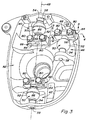
- Fig. 3
- is a perspective view of the steering knuckle and ball joints of the present invention,
- Fig. 4
- is a sectional view through the ball joint and steering knuckle as seen from the line 4-4 of Fig. 3, and
- Fig. 5
- is a sectional view through the ball joint mounting cap and steering knuckle as seen from the line 5-5 of Fig. 3.
- With reference to Fig. 1, a
tractor 10 having the ball joints of the present invention is shown. Thetractor 10 includesrear tires 12 andfront tires 14. The front tires are steering tires and rotate about upright turning axes to steer the vehicle. Rotation of thewheels 14 about the turning axes is provided through a steering knuckle mounted at each end of the front axle through the ball joints of the present invention. - With reference to Fig. 2, the right hand side of a
front axle 16 and suspension is shown in greater detail. The lefthand side is essentially a mirror image of the right hand side although some differences may exist. The mechanical front wheel drive includes a front drivedifferential case 18 that is part of the tractor frame or attached thereto. Afront drive shaft 20 extends to the right from the differential case to provide rotational power to the planetary final drive in thewheel hub 22. A wheel (not shown) is bolted to theflange 23 of the hub. Thehub 22 is carried by asteering knuckle 24 that is in turn carried by upper andlower control arms proximal ends differential case 18 whereby the distal ends 34 and 36 can move up and down to raise and lower thefront tires 14 relative to thedifferential case 18. Ahydraulic cylinder 38 extends between thedifferential case 18 and thelower control arm 28 to support the load of the suspended mass. Thecylinder 38 is coupled to a gas accumulator (not shown) to function as a spring. Thedistal ends lower control arms steering knuckle 24 through upper and lowerball joint assemblies turning axis 48. - A
steering tie rod 44 extends from asteering cylinder 45 carried by thedifferential case 18. Thedistal end 47 of thetie rod 44 is coupled to thesteering knuckle 24 through aball joint assembly 46. The steeringball joint assembly 46 is spaced from theturning axis 48 whereby extension or retraction of the tie rod causes thesteering knuckle 24 and hence thetire 14 to rotate about theturning axis 48. - Each
ball joint assembly ball stud 50. Theball studs 50 are essentially the same in structure and are preferably of the same dimension, however, different sizedball studs 50 could be used in the three differentball joint assemblies ball stud 50 includes aspherical ball portion 52 and a pair of oppositely extendingstuds ball portions 52 of theball studs 50 used for the upper andlower control arms lubrication grooves 86 circumscribing the ball portions. - The
stud 54 of eachball stud 50 is seated into abore 58 in thesteering knuckle 24. Thebores 58 have a firstlarger portion 60 into which thestud 54 is press fit and a smaller diameter throughportion 62 formingshoulders 88 forming stops in each bore for engagement of thestuds 54. During initial assembly, thestuds 54 are press fit into thelarger portions 60 of thebores 58. Thestuds 54 include an internal threadedbore 64 used during a field service where a press is not available. A threaded member is inserted in thebore 54 and is used to draw thestud 54 into thebore portion 60 of the knuckle. - The
stud 56 is secured to the knuckle by acap 66. Thecap 66 includes afirst bore 68 receiving thestud 56 of theball stud 50. A pair of cross bores 70, 72 extend through thecap 66 on both sides of thebore 68 and at a 90° angle relative to thebore 68.Dowels 74 are disposed in thebores cap 66 and into alarge diameter portion 76 ofbores 78 in thesteering knuckle 74. Threadedfasteners 80 extend through thedowels 74 and are threaded into thesmaller diameter portions 82 of thebores 78. Thedowels 74 provide greater shear strength to the attachment of thecap 66 to theknuckle 24 than is possible solely with thefasteners 80. - The
cap 66 has aslot 84 extending through the cross bore 72 to thebore 68. When thefastener 80 is threaded through thebore 72, theslot 84 is closed, whereby thecap 66 clamps upon thestud 56 to grip theball stud 50 and prevent rotation of theball stud 50. - The
control arms tie rod 44 include spherical arrangements at their outer ends to surround theball portions 52 of each of theball studs 50 in a conventional manner. The ball joints allow thetie rod 44 and controlarms steering knuckle 24. - The
steering knuckle 24 is pan shaped with a recess on the inboard side formed by sidewalls 90 that extend toward thedifferential case 18. This creates arecess 92 in which the ball joints are positioned. Thewalls 90 surround the ball joints on all sides except for the inner side facing thedifferential case 18. This shields the ball joints from dirt and mud, particularly that thrown from thefront tires 14. - The ball
joint assemblies dual studs front axle 16. - The invention should not be limited to the above-described embodiment, but should be limited solely by the claims.
Claims (13)
- An axle assembly for a tractor comprising:a steering knuckle (24); andat least one ball joint (40, 42, 46) attached to the steering knuckle (24), the ball joint (40, 42, 46) having a ball stud (50) with a spherical ball portion (52) and at least one stud (54, 56) extending therefrom and coupled to the steering knuckle (24).
- The axle assembly as defined by claim 1 wherein the ball joint (40, 42, 46) has a ball stud (50) with a spherical ball portion (52) and a pair of oppositely extending studs (54, 56) fixed to the steering knuckle (24).
- The axle assembly as defined by claim 1 or 2 wherein the steering knuckle (24) has a concave inboard side forming a recess (92) into which at least one of the ball stud (50) of the ball joint (40, 42, 46) is disposed.
- The axle assembly as defined by one or more of the preceding claims wherein the axle assembly is a front wheel axle assembly comprising steering tie rod (44) coupled to the ball stud (50).
- The axle assembly as defined by one or more of the preceding claims further comprising a suspension control arm (26, 28) coupled to the ball stud (50).
- The axle assembly as defined by one or more of the preceding claims further comprising three of the ball joints (40, 42, 46), the ball joints (40, 42, 46) including upper and lower ball joints (40, 42) and a steering ball joint (46);upper and lower controls (26, 28) coupled to the upper and lower ball joints (40, 42) to define a turning axis (48) for the steering knuckle (24); anda steering tie rod (44) coupled to the steering ball joint (46).
- The axle assembly as defined by one or more of the preceding claims wherein a first stud (56) of the ball stud (50) is press fit into an aperture (60) in the steering knuckle (24).
- The axle assembly as defined by one or more of the preceding claims wherein a second stud (54) of each ball stud (50) is fixed to the knuckle (24) through a cap (66) fixed to the steering knuckle (24).
- The axle assembly as defined by claim 8 wherein the cap (66) includes a bore (68) receiving the second stud (54) of the ball stud (50) and a pair of apertures (70, 72) with threaded fasteners (80) extending therethrough and into the steering knuckle (24) for fixing the cap (66) to the steering knuckle (24).
- The axle assembly as defined by claim 9 wherein the cap (66) includes a slot (84) extending through one fastener aperture (72) and to the stud bore (68) wherein the stud bore (68) clamps on the second stud (54) to prevent rotation of the ball stud (50) relative to the steering knuckle (24).
- The axle assembly as defined by claim 10 further comprising a dowel (74) within the fastener bores (7o, 72) in the cap (66) and extending into the steering knuckle (24).
- A tractor comprising:a frame (18);upper and lower control arms (26, 28) mounted to the frame (18) and extending laterally outward for pivotal motion about upper and lower axes respectively for up and down motion of distal ends (34, 36) of the control arms (26, 28);a steering knuckle (24) attached to the distal ends (34, 36) of the control arms (26, 28) through upper and lower ball joints (40, 42) respectively to define a turning axis (48) for the steering knuckle (24) and to allow the knuckle (24) to move up and down relative to the frame (18);a steering tie rod (44) coupled to the steering knuckle (24) through a steering ball joint (46) spaced from the turning axis (48) whereby the tie rod (44) can apply a steering force to the knuckle (24) to rotate the knuckle (24) about the turning axis (48); andthe upper, lower and steering ball joints (40, 42, 46) each having a ball stud (50) with a spherical ball portion (52) and a pair of oppositely extending studs (54, 56) fixed to the steering knuckle (24).
- The tractor as defined by claim 12 comprising an axle assembly as defined by one or more of the claims 1 to 11.
Applications Claiming Priority (2)
| Application Number | Priority Date | Filing Date | Title |
|---|---|---|---|
| US662609 | 2000-09-14 | ||
| US09/662,609 US6402169B1 (en) | 2000-09-14 | 2000-09-14 | Steering knuckle and ball joint assembly for tractor front axle |
Publications (3)
| Publication Number | Publication Date |
|---|---|
| EP1188641A2 true EP1188641A2 (en) | 2002-03-20 |
| EP1188641A3 EP1188641A3 (en) | 2005-03-30 |
| EP1188641B1 EP1188641B1 (en) | 2007-11-07 |
Family
ID=24658410
Family Applications (1)
| Application Number | Title | Priority Date | Filing Date |
|---|---|---|---|
| EP01120830A Expired - Lifetime EP1188641B1 (en) | 2000-09-14 | 2001-08-30 | Axle assembly and tractor comprising an axle assembly |
Country Status (8)
| Country | Link |
|---|---|
| US (1) | US6402169B1 (en) |
| EP (1) | EP1188641B1 (en) |
| JP (1) | JP2002127930A (en) |
| AR (1) | AR037078A1 (en) |
| AT (1) | ATE377544T1 (en) |
| BR (1) | BR0104081B1 (en) |
| CA (1) | CA2344136C (en) |
| DE (1) | DE60131230T2 (en) |
Cited By (2)
| Publication number | Priority date | Publication date | Assignee | Title |
|---|---|---|---|---|
| EP1600311A1 (en) * | 2004-05-26 | 2005-11-30 | AGCO GmbH | Tractor with front suspension |
| CN109070949A (en) * | 2016-11-30 | 2018-12-21 | 本田技研工业株式会社 | Autonomous driving vehicle |
Families Citing this family (14)
| Publication number | Priority date | Publication date | Assignee | Title |
|---|---|---|---|---|
| US6470991B1 (en) * | 2000-09-14 | 2002-10-29 | Deere & Company | Tractor with front suspension |
| DE60235670D1 (en) * | 2001-05-03 | 2010-04-29 | Technology Investments Ltd | Modular ball joint arrangement |
| US7419172B2 (en) * | 2005-09-21 | 2008-09-02 | Shine Far Metal Industry Co., Ltd. | Knuckle arm for vehicles |
| US20080240847A1 (en) * | 2007-04-02 | 2008-10-02 | Stephen Kent Crouse | Eccentric Mount Ball Stud For Steering Toe Adjustment |
| US11772702B2 (en) | 2016-02-09 | 2023-10-03 | Soucy International Inc. | Steering knuckle gearbox assembly |
| WO2017137927A2 (en) * | 2016-02-09 | 2017-08-17 | Soucy International Inc. | Steering knuckle, steerable track system, and vehicle |
| US10343716B2 (en) * | 2017-04-03 | 2019-07-09 | Robby Gordon | Universal axle-hub assembly |
| US9988083B1 (en) * | 2017-07-27 | 2018-06-05 | Justin Smith | Tie rod connection pivot assembly |
| US10717465B2 (en) | 2017-11-01 | 2020-07-21 | Deere & Company | Steerable knuckle |
| US10737719B2 (en) | 2017-11-01 | 2020-08-11 | Deere & Company | Steerable knuckle |
| US10894569B2 (en) | 2018-04-06 | 2021-01-19 | Deere & Company | Track support member and assembly |
| US11292515B2 (en) * | 2020-03-27 | 2022-04-05 | Deere & Company | Compact steering assembly |
| US20220305857A1 (en) * | 2021-03-24 | 2022-09-29 | Mf Ip Holding, Llc | Suspension system for a vehicle and method of adjusting rear control arm geometry for same |
| ZA202209502B (en) * | 2021-08-27 | 2024-02-28 | Joy Global Underground Mining Llc | Bearing assembly for a wheel unit |
Family Cites Families (15)
| Publication number | Priority date | Publication date | Assignee | Title |
|---|---|---|---|---|
| US4437529A (en) * | 1982-05-03 | 1984-03-20 | Ingersoll Equipment Co., Inc. | Detachable hinge assembly |
| GB2155989B (en) * | 1984-03-21 | 1987-02-11 | Quinton Hazell Holdings Ltd | A ball joint |
| US4722540A (en) * | 1984-11-13 | 1988-02-02 | The Budd Company | Steering knuckle assembly |
| US4618159A (en) * | 1984-11-13 | 1986-10-21 | The Budd Company | Steering knuckle assembly |
| JPS62132867U (en) * | 1986-02-18 | 1987-08-21 | ||
| US4761019A (en) * | 1987-09-04 | 1988-08-02 | Chrysler Motors Corporation | Steering knuckle assembly |
| JPH0349104U (en) * | 1989-09-22 | 1991-05-13 | ||
| JP3122728B2 (en) * | 1992-04-28 | 2001-01-09 | 本田技研工業株式会社 | Automotive wheel suspension |
| US5366233A (en) * | 1992-05-18 | 1994-11-22 | The Budd Company | Wire form steering arm link |
| JPH06344737A (en) * | 1993-06-07 | 1994-12-20 | Toyota Motor Corp | Double wishbone type suspension |
| IT1288134B1 (en) * | 1996-05-30 | 1998-09-10 | Sasib Railway Electrification | COMPOSITE STRUCTURE AND PROCEDURE FOR ITS ASSEMBLY. |
| JPH10244954A (en) * | 1997-03-06 | 1998-09-14 | Hino Motors Ltd | Steering device |
| US5931597A (en) | 1997-10-16 | 1999-08-03 | Trw Inc. | Ball joint |
| JPH11255141A (en) * | 1998-03-11 | 1999-09-21 | Suzuki Motor Corp | Steering knuckle |
| US6231264B1 (en) * | 1998-11-12 | 2001-05-15 | The Pullman Company | Torque rod bearing assembly |
-
2000
- 2000-09-14 US US09/662,609 patent/US6402169B1/en not_active Expired - Lifetime
-
2001
- 2001-04-17 CA CA002344136A patent/CA2344136C/en not_active Expired - Fee Related
- 2001-08-30 AT AT01120830T patent/ATE377544T1/en not_active IP Right Cessation
- 2001-08-30 EP EP01120830A patent/EP1188641B1/en not_active Expired - Lifetime
- 2001-08-30 DE DE60131230T patent/DE60131230T2/en not_active Expired - Lifetime
- 2001-09-13 JP JP2001277585A patent/JP2002127930A/en active Pending
- 2001-09-13 AR ARP010104345A patent/AR037078A1/en unknown
- 2001-09-14 BR BRPI0104081-2A patent/BR0104081B1/en not_active IP Right Cessation
Non-Patent Citations (1)
| Title |
|---|
| None |
Cited By (2)
| Publication number | Priority date | Publication date | Assignee | Title |
|---|---|---|---|---|
| EP1600311A1 (en) * | 2004-05-26 | 2005-11-30 | AGCO GmbH | Tractor with front suspension |
| CN109070949A (en) * | 2016-11-30 | 2018-12-21 | 本田技研工业株式会社 | Autonomous driving vehicle |
Also Published As
| Publication number | Publication date |
|---|---|
| US6402169B1 (en) | 2002-06-11 |
| DE60131230D1 (en) | 2007-12-20 |
| CA2344136C (en) | 2004-08-10 |
| BR0104081B1 (en) | 2009-05-05 |
| DE60131230T2 (en) | 2008-09-04 |
| EP1188641A3 (en) | 2005-03-30 |
| ATE377544T1 (en) | 2007-11-15 |
| CA2344136A1 (en) | 2002-03-14 |
| JP2002127930A (en) | 2002-05-09 |
| EP1188641B1 (en) | 2007-11-07 |
| BR0104081A (en) | 2002-05-07 |
| AR037078A1 (en) | 2004-10-20 |
Similar Documents
| Publication | Publication Date | Title |
|---|---|---|
| EP1188641B1 (en) | Axle assembly and tractor comprising an axle assembly | |
| AU781378B2 (en) | Tractor with front suspension | |
| US6905129B2 (en) | Wishbone for an automotive suspension | |
| US6267526B1 (en) | Headed solid rod for torque rod spacer | |
| JP3321047B2 (en) | Pivotable spring mounted axle suspension | |
| JP5555403B2 (en) | Adjustable casting apex V type torque rod | |
| JP2004521826A (en) | Rear axle of a passenger car with five individual links | |
| CN109955671B (en) | Strut type suspension device | |
| GB2351952A (en) | Torque rod apex mount | |
| EP1370430B1 (en) | Agricultural tractor with draft compensating suspension | |
| JP3500897B2 (en) | Car front body structure | |
| US5765858A (en) | Wheel suspension for rear wheels | |
| EP3272625A1 (en) | Hydraulic cylinder for utility vehicle | |
| KR200171146Y1 (en) | Rolling device of power truck | |
| JP3724044B2 (en) | Automobile front structure | |
| US11173955B2 (en) | Wheel support apparatus | |
| JP2696551B2 (en) | Control arm support structure for suspension system | |
| JP2696564B2 (en) | Automotive wheel suspension | |
| JPH0547746Y2 (en) | ||
| JP2546397Y2 (en) | Tractor axle case mounting structure | |
| GB2577400A (en) | Crash Structure | |
| JP3912730B2 (en) | Vehicle front wheel steering device | |
| JPH0332415Y2 (en) | ||
| JPH05301581A (en) | Tractor axle frame structure | |
| JPH0568702U (en) | Car suspension |
Legal Events
| Date | Code | Title | Description |
|---|---|---|---|
| PUAI | Public reference made under article 153(3) epc to a published international application that has entered the european phase |
Free format text: ORIGINAL CODE: 0009012 |
|
| AK | Designated contracting states |
Kind code of ref document: A2 Designated state(s): AT BE CH CY DE DK ES FI FR GB GR IE IT LI LU MC NL PT SE TR |
|
| AX | Request for extension of the european patent |
Free format text: AL;LT;LV;MK;RO;SI |
|
| PUAL | Search report despatched |
Free format text: ORIGINAL CODE: 0009013 |
|
| AK | Designated contracting states |
Kind code of ref document: A3 Designated state(s): AT BE CH CY DE DK ES FI FR GB GR IE IT LI LU MC NL PT SE TR |
|
| AX | Request for extension of the european patent |
Extension state: AL LT LV MK RO SI |
|
| 17P | Request for examination filed |
Effective date: 20050930 |
|
| AKX | Designation fees paid |
Designated state(s): AT BE CH CY DE DK ES FI FR GB GR IE IT LI LU MC NL PT SE TR |
|
| GRAP | Despatch of communication of intention to grant a patent |
Free format text: ORIGINAL CODE: EPIDOSNIGR1 |
|
| GRAS | Grant fee paid |
Free format text: ORIGINAL CODE: EPIDOSNIGR3 |
|
| GRAA | (expected) grant |
Free format text: ORIGINAL CODE: 0009210 |
|
| AK | Designated contracting states |
Kind code of ref document: B1 Designated state(s): AT BE CH CY DE DK ES FI FR GB GR IE IT LI LU MC NL PT SE TR |
|
| REG | Reference to a national code |
Ref country code: GB Ref legal event code: FG4D |
|
| REG | Reference to a national code |
Ref country code: IE Ref legal event code: FG4D |
|
| REG | Reference to a national code |
Ref country code: CH Ref legal event code: EP |
|
| REF | Corresponds to: |
Ref document number: 60131230 Country of ref document: DE Date of ref document: 20071220 Kind code of ref document: P |
|
| PG25 | Lapsed in a contracting state [announced via postgrant information from national office to epo] |
Ref country code: LI Free format text: LAPSE BECAUSE OF FAILURE TO SUBMIT A TRANSLATION OF THE DESCRIPTION OR TO PAY THE FEE WITHIN THE PRESCRIBED TIME-LIMIT Effective date: 20071107 Ref country code: CH Free format text: LAPSE BECAUSE OF FAILURE TO SUBMIT A TRANSLATION OF THE DESCRIPTION OR TO PAY THE FEE WITHIN THE PRESCRIBED TIME-LIMIT Effective date: 20071107 Ref country code: NL Free format text: LAPSE BECAUSE OF FAILURE TO SUBMIT A TRANSLATION OF THE DESCRIPTION OR TO PAY THE FEE WITHIN THE PRESCRIBED TIME-LIMIT Effective date: 20071107 Ref country code: ES Free format text: LAPSE BECAUSE OF FAILURE TO SUBMIT A TRANSLATION OF THE DESCRIPTION OR TO PAY THE FEE WITHIN THE PRESCRIBED TIME-LIMIT Effective date: 20080218 Ref country code: SE Free format text: LAPSE BECAUSE OF FAILURE TO SUBMIT A TRANSLATION OF THE DESCRIPTION OR TO PAY THE FEE WITHIN THE PRESCRIBED TIME-LIMIT Effective date: 20080207 |
|
| NLV1 | Nl: lapsed or annulled due to failure to fulfill the requirements of art. 29p and 29m of the patents act | ||
| REG | Reference to a national code |
Ref country code: CH Ref legal event code: PL |
|
| PG25 | Lapsed in a contracting state [announced via postgrant information from national office to epo] |
Ref country code: AT Free format text: LAPSE BECAUSE OF FAILURE TO SUBMIT A TRANSLATION OF THE DESCRIPTION OR TO PAY THE FEE WITHIN THE PRESCRIBED TIME-LIMIT Effective date: 20071107 |
|
| ET | Fr: translation filed | ||
| PG25 | Lapsed in a contracting state [announced via postgrant information from national office to epo] |
Ref country code: DK Free format text: LAPSE BECAUSE OF FAILURE TO SUBMIT A TRANSLATION OF THE DESCRIPTION OR TO PAY THE FEE WITHIN THE PRESCRIBED TIME-LIMIT Effective date: 20071107 |
|
| PG25 | Lapsed in a contracting state [announced via postgrant information from national office to epo] |
Ref country code: BE Free format text: LAPSE BECAUSE OF FAILURE TO SUBMIT A TRANSLATION OF THE DESCRIPTION OR TO PAY THE FEE WITHIN THE PRESCRIBED TIME-LIMIT Effective date: 20071107 |
|
| PLBE | No opposition filed within time limit |
Free format text: ORIGINAL CODE: 0009261 |
|
| STAA | Information on the status of an ep patent application or granted ep patent |
Free format text: STATUS: NO OPPOSITION FILED WITHIN TIME LIMIT |
|
| PG25 | Lapsed in a contracting state [announced via postgrant information from national office to epo] |
Ref country code: PT Free format text: LAPSE BECAUSE OF FAILURE TO SUBMIT A TRANSLATION OF THE DESCRIPTION OR TO PAY THE FEE WITHIN THE PRESCRIBED TIME-LIMIT Effective date: 20080407 |
|
| 26N | No opposition filed |
Effective date: 20080808 |
|
| PG25 | Lapsed in a contracting state [announced via postgrant information from national office to epo] |
Ref country code: GR Free format text: LAPSE BECAUSE OF FAILURE TO SUBMIT A TRANSLATION OF THE DESCRIPTION OR TO PAY THE FEE WITHIN THE PRESCRIBED TIME-LIMIT Effective date: 20080208 |
|
| PG25 | Lapsed in a contracting state [announced via postgrant information from national office to epo] |
Ref country code: FI Free format text: LAPSE BECAUSE OF FAILURE TO SUBMIT A TRANSLATION OF THE DESCRIPTION OR TO PAY THE FEE WITHIN THE PRESCRIBED TIME-LIMIT Effective date: 20071107 |
|
| PG25 | Lapsed in a contracting state [announced via postgrant information from national office to epo] |
Ref country code: MC Free format text: LAPSE BECAUSE OF NON-PAYMENT OF DUE FEES Effective date: 20080831 |
|
| PG25 | Lapsed in a contracting state [announced via postgrant information from national office to epo] |
Ref country code: IE Free format text: LAPSE BECAUSE OF NON-PAYMENT OF DUE FEES Effective date: 20080901 Ref country code: CY Free format text: LAPSE BECAUSE OF FAILURE TO SUBMIT A TRANSLATION OF THE DESCRIPTION OR TO PAY THE FEE WITHIN THE PRESCRIBED TIME-LIMIT Effective date: 20071107 |
|
| PGFP | Annual fee paid to national office [announced via postgrant information from national office to epo] |
Ref country code: FR Payment date: 20090817 Year of fee payment: 9 |
|
| PGFP | Annual fee paid to national office [announced via postgrant information from national office to epo] |
Ref country code: GB Payment date: 20090825 Year of fee payment: 9 |
|
| PGFP | Annual fee paid to national office [announced via postgrant information from national office to epo] |
Ref country code: IT Payment date: 20090826 Year of fee payment: 9 |
|
| PG25 | Lapsed in a contracting state [announced via postgrant information from national office to epo] |
Ref country code: LU Free format text: LAPSE BECAUSE OF NON-PAYMENT OF DUE FEES Effective date: 20080830 |
|
| PG25 | Lapsed in a contracting state [announced via postgrant information from national office to epo] |
Ref country code: TR Free format text: LAPSE BECAUSE OF FAILURE TO SUBMIT A TRANSLATION OF THE DESCRIPTION OR TO PAY THE FEE WITHIN THE PRESCRIBED TIME-LIMIT Effective date: 20071107 |
|
| GBPC | Gb: european patent ceased through non-payment of renewal fee |
Effective date: 20100830 |
|
| REG | Reference to a national code |
Ref country code: FR Ref legal event code: ST Effective date: 20110502 |
|
| PG25 | Lapsed in a contracting state [announced via postgrant information from national office to epo] |
Ref country code: IT Free format text: LAPSE BECAUSE OF NON-PAYMENT OF DUE FEES Effective date: 20100830 |
|
| PG25 | Lapsed in a contracting state [announced via postgrant information from national office to epo] |
Ref country code: FR Free format text: LAPSE BECAUSE OF NON-PAYMENT OF DUE FEES Effective date: 20100831 |
|
| PG25 | Lapsed in a contracting state [announced via postgrant information from national office to epo] |
Ref country code: GB Free format text: LAPSE BECAUSE OF NON-PAYMENT OF DUE FEES Effective date: 20100830 |
|
| PGFP | Annual fee paid to national office [announced via postgrant information from national office to epo] |
Ref country code: DE Payment date: 20180719 Year of fee payment: 18 |
|
| REG | Reference to a national code |
Ref country code: DE Ref legal event code: R119 Ref document number: 60131230 Country of ref document: DE |
|
| PG25 | Lapsed in a contracting state [announced via postgrant information from national office to epo] |
Ref country code: DE Free format text: LAPSE BECAUSE OF NON-PAYMENT OF DUE FEES Effective date: 20200303 |