JP3912730B2 - Vehicle front wheel steering device - Google Patents
Vehicle front wheel steering device Download PDFInfo
- Publication number
- JP3912730B2 JP3912730B2 JP2001391411A JP2001391411A JP3912730B2 JP 3912730 B2 JP3912730 B2 JP 3912730B2 JP 2001391411 A JP2001391411 A JP 2001391411A JP 2001391411 A JP2001391411 A JP 2001391411A JP 3912730 B2 JP3912730 B2 JP 3912730B2
- Authority
- JP
- Japan
- Prior art keywords
- case
- front axle
- axle case
- cylinder
- front wheel
- Prior art date
- Legal status (The legal status is an assumption and is not a legal conclusion. Google has not performed a legal analysis and makes no representation as to the accuracy of the status listed.)
- Expired - Fee Related
Links
Images


Landscapes
- Power Steering Mechanism (AREA)
Description
【0001】
【発明の属する技術分野】
本発明は、車輛の前輪操向装置に関し、特に、前輪操向用の油圧シリンダ装置をフロントアクスルケースに沿設した車輛の前輪操向装置に関する。
【0002】
【従来の技術】
この種、車輛の前輪操向装置として、フロントアクスルケースと油圧シリンダ装置を別体で設けたものでは、フロントアクスルケースに設けるスイングセンタ部(揺動支持部)の強度が弱くなると共に、フロントアクスルケースの軸方向の中心と油圧シリンダ装置の軸方向の中心との間隔が大きくなるため、規定の前輪切れ角を得るために、長い油圧シリンダ装置のストロークを要することが知られている。
【0003】
これに対し、例えば実開平5−58560号公報に記載の技術によれば、フロントアクスルケースと前輪操向用の油圧シリンダとを、取付ブラケットとボルトにより一体的に固定している。
【0004】
また、特開昭62−225461号公報によれば、フロントアクスルケースにシリンダ筒をボルトにて一体的に固定していると共に、図6に示すように、軸受101を介してデフ駆動軸102を支持する軸受ケース100を有し、前記デフ駆動軸102よりも下方側に、前輪操向用の油圧シリンダ104のシリンダ筒をフロントアクスルケース106に一体的にボルト固定し、更に、該フロントアクスルケース106から前後に軸部108,108を突設し、この軸部108を、取付装置110,110に形成した凹部112に嵌合することで、フロントアクスルケース106を前後方向の軸心廻りに揺動自在に支持している。
【0005】
【発明が解決しようとする課題】
しかしながら、前述した各従来例によると、いずれもフロントアクスルケースと前輪操向用の油圧シリンダのシリンダケースとを、ボルト等の固定手段により一体的に固定したものであるため、成形手段により一体成形したものに比べ、フロントアクスルケースの機械的強度の向上(補強)という点で、効果が劣るものであった。
【0006】
また、前記シリンダケースをフロントアクスルケースの上下揺動支持部から離れた位置に配置したのでは、同様に、フロントアクスルケースの機械的強度の向上(補強)という点で、効果が劣ることになる。
【0007】
更に、前述した特開昭62−225461号公報に記載の従来例では、フロントアクスルケース106から突設した軸部108を、取付装置110に形成した凹部112に嵌合することで揺動自在に支持しているが、フロントアクスルケース106から突設した前記軸部108を加工するのは、フロントアクスルケース106が長尺物ゆえ、これを前後方向の軸心廻りに回転させる必要があるため極めて困難である。
【0008】
本発明は、斯かる課題を解決するためになされたもので、その目的とするところは、フロントアクスルケースの機械的強度を高めることができると共に、組立工数の削減を図り得る車輛の前輪操向装置を提供することにある。
【0009】
【課題を解決するための手段】
前記目的を達成するため、請求項1記載の発明は、前輪パワーステアリング操向用の油圧シリンダ装置(30)を、フロントアクスルケース(28)に沿設した車輛の前輪操向装置において、
前記フロントアクスルケース(28)と前記油圧シリンダ装置(30)のシリンダケース(31)とを一体成形すると共に、前記フロントアクスルケース(28)に形成した軸受部(28a)を機体側に設けたセンターピン(32a)に回動自在に嵌合して該フロントアクスルケースを上下揺動自在に支持し、
前記フロントアクスルケース(28)に一体成形されたシリンダケース(31)が前記軸受部(28a)の上方に配置されたことを特徴とする。
【0010】
請求項2記載の発明は、請求項1記載の車輛の前輪操向装置において、前記センターピン(32a)を有するフロントブラケット(32)の両端部(32c,32c)が、エンジン(12)の左右両側から前方に向けて延出する左右の固定フレーム(36,36)に取付けられ、前記シリンダケース(31)の軸方向長さを前記左右の固定フレーム(36,36)の対面長さよりも短く構成したことを特徴とする。
【0011】
〔作用〕
本発明によれば、フロントアクスルケース(28)と油圧シリンダ装置(30)のシリンダケース(31)とを一体成形したことで、フロントアクスルケース(28)がシリンダケース(31)によって補強されることになり該フロントアクスルケース(28)の機械的強度が高められると共に、このシリンダケース(31)をフロントアクスルケース(28)の上下揺動支持部(28a)の上方に配置したことで、特に多大な荷重が加わることが予想される上下揺動支持部(28a)付近のフロントアクスルケース(28)の機械的強度が高められるという利点を有する。
【0012】
なお、括弧内の符号は、図面を参照するためのもので、本発明を何ら限定するものではない。
【0013】
【発明の実施の形態】
以下、図面に基づき本発明の実施の形態を説明する。
【0014】
図1は、本発明が適用されたトラクタの外観斜視図である。同図において、トラクタ10は、エンジン12及びミッションケース14等から構成される走行機体11を有し、該走行機体11は操向輪である前輪16、及び後輪18により支持されている。前記エンジン12はボンネット20に覆われ、該ボンネット20後方の運転席22には、ハンドル24と座席26を有している。
【0015】
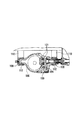
図2〜図4は、前輪操向装置を構成するフロントアクスルケース28とこれに沿設された油圧シリンダ装置30の構成を示す図である。
【0016】
本実施の形態では、フロントアクスルケース28と油圧シリンダ装置30のシリンダケース31とを一体成形すると共に、該シリンダケース31を、フロントアクスルケース28の上下揺動支持部の近傍に配置した。
【0017】
フロントアクスルケース28は、前輪駆動用の歯車装置を内蔵していて、このフロントアクスルケース28と油圧シリンダ装置30のシリンダケース31とは、金型等の適宜成形手段により一体成形されている。更に、このシリンダケース31は、フロントアクスルケース28の上下揺動支持部の上方に配置されている。
【0018】
すなわち、フロントアクスルケース28は、機体前方のフロントブラケット32と後方のリヤブラケット34にて機体前後方向の軸心廻りに上下揺動自在に支持されている。そして、フロントアクスルケース28の機体左右側に延びる軸方向の略々中央部には、軸線を機体前後方向に向けた軸受部(上下揺動支持部)28aが形成されている。一方、フロントブラケット32には、この軸受部28aに回動可能に嵌合されるセンターピン32aが機体後方に突出形成されている。前記フロントブラケット32は、センターピン32aを中心として該センターピン32aを懸垂するように、左右略々対称かつ斜め上方に向けて支持アーム32b,32bが延設されている。この支持アーム32bの先端側には、固定片32cが一体的に取付けられている。
【0019】
フロントブラケット32は、この固定片32c,32cを介して走行機体11を構成するメインフレーム(固定フレーム)36に固定されている。該メインフレーム36は、エンジン12の左右両側から前方に向けて夫々延出されていて、後方のリヤブラケット34は、エンジン12のオイルパンの下部に取付部材38を介して、機体前後方向の軸心廻りに揺動自在に支持されている。
【0020】
このため、フロントアクスルケース28は、軸受部28aに嵌合されるセンターピン32aにより機体前後方向の軸心廻りに上下揺動自在に支持されることとなり、例えば機体が不整地走行で左右いずれかの前輪16が凹凸面を走行すると、フロントアクスルケース28は軸受部28aに支持されたセンターピン32aの回りに揺動することができる。このセンターピン32aと軸受部28aの作用により、機体の急激な昇降時に加わる衝撃力が緩和されると共に、機体左右側が過度に上下に傾斜するのが緩和される等の利点を有する。
【0021】
また、本実施の形態によれば、フロントアクスルケース28とシリンダケース31とを一体成形したことで、図4に示すように、油圧シリンダ装置30のピストンロッド30aとフロントアクスルケース28の双方の軸方向の中心線同士の間隔Lを近接することができるため、該ピストンロッド30aを短ストロークにて所定の前輪ステアリング切れ角を得ることができる。
【0022】
更に、本実施の形態では、シリンダケース31の軸方向長さを、エンジン12の左右両側から前方に向けて延出する左右の固定フレーム36,36の対面長さよりも短く構成している。
【0023】
すなわち、図3に示すように、フロントアクスルケース14と一体のシリンダケース31が、センターピン32aを中心とする半径で弧を描くように上下揺動したとき、該シリンダケース31の左右端部がメインフレーム36,36の下端部に干渉しない程度に、シリンダケース31の軸方向長さが固定フレーム36,36の対面長さよりも短く設定されている。なお、シリンダケース31の軸方向長さが固定フレーム36,36の対面長さよりも短ければ問題はなく、また、図に示すように、これらが略々等しい線上にあっても、センターピン32aを中心とする半径で弧を描くように上下揺動したときに相互に干渉しない程度であれば良い。
【0024】
このように、本実施の形態では、シリンダケース31とメインフレーム36との干渉を考慮する必要がないため、干渉防止のためにメインフレーム36の一部を切欠く必要もなく、かつ、切欠工数の削減を図ることができる。
【0025】
ところで、フロントアクスルケース28の軸方向の外側端部には、夫々キングピンケース40とファイナルケース41が固定され、キングピンケース40は略々上下方向に延びるキングビン(図示せず)を支持している。このキングビンはギヤ機構を介してホイールシャフト46に連結されている。キングピンケース40の上部には、ナックルアーム42が回動可能に取付けられている。このナックルアーム42は、ジョイント44を介して後述するピストンロッド30aに連結されている。
【0026】
図5は、油圧シリンダ装置30の詳細を示す図であり、シリンダケース31の左右端部には、図示しない油圧ポンプと油圧タンクにつながる油圧ポート37が設けられている。また、シリンダケース31の左右外側の端部には、ボルト43,43によりプラグ39,39がシリンダケース31に固定されている。このプラグ39には、外側端部の内径部にOリング35,35が装着され、該内径側にピストンロッド30aが摺動可能に嵌挿されている。更に、該ピストンロッド30aの長手方向の略々中央部にはピストン30bが、シリンダケース31の内径側を摺動可能に嵌挿されている。このピストン30bの外径部には、Oリング35’が装着されている。
【0027】
【発明の効果】
請求項1記載の発明によれば、フロントアクスルケースと油圧シリンダ装置のシリンダケースとを一体成形すると共に、該シリンダケースを、フロントアクスルケースの上下揺動支持部の上方に配置したことで、フロントアクスルケースがシリンダケースにより補強されて該フロントアクスルケースの機械的強度を高めることができると共に、フロントアクスルケースとシリンダケースを個別に形成し固定具で固定した場合に比して、締結部分等がなくなり外観を美麗にすることができ、更に組立て工数の削減を図ることができると共に、材料費を節約することができる。
【0028】
また、本発明によれば、シリンダケースとフロントアクスルケースを一体成形して、双方の中心軸線同士を近接することができるため、該シリンダケース内を摺動するピストンロッドを短ストロークにて所定の前輪ステアリング切れ角を得ることができる。
【0029】
請求項2記載の発明によれば、シリンダケースの軸方向長さを、エンジンの左右両側から前方に向けて延出する固定フレームの対面長さよりも短く構成したので、フロントアクスルケースが上下揺動支持部を中心として上下にスイングしたとしても、シリンダケースが固定フレームに干渉しないため、干渉防止のために固定フレームの一部を切欠く必要がなく、切欠工数の削減を図ることができると共に、固定フレームの機械的強度をそのまま維持することができる。
【図面の簡単な説明】
【図1】本発明が適用されたトラクタの外観斜視図である。
【図2】フロントアクスルケースと油圧シリンダ装置の平面図である。
【図3】同上の正面図である。
【図4】同上の側面図である。
【図5】油圧シリンダ装置の断正面図である。
【図6】トラクタにおける前輪操向装置の従来例を示す図である。
【符号の説明】
10 トラクタ
11 走行機体
28 フロントアクスルケース
28a 軸受部(上下揺動支持部)
30 油圧シリンダ装置
30a ピストンロッド
30b ピストン
31 シリンダケース
32 フロントブラケット
32a センターピン
32b 支持アーム
34 リヤブラケット
36 メインフレーム(固定フレーム)[0001]
BACKGROUND OF THE INVENTION
The present invention relates to a vehicle front wheel steering device, and more particularly to a vehicle front wheel steering device in which a hydraulic cylinder device for steering a front wheel is provided along a front axle case.
[0002]
[Prior art]
In this type of vehicle front wheel steering device, a front axle case and a hydraulic cylinder device are provided separately, and the strength of the swing center portion (swing support portion) provided in the front axle case is weakened. Since the distance between the axial center of the case and the axial center of the hydraulic cylinder device increases, it is known that a long stroke of the hydraulic cylinder device is required to obtain a prescribed front wheel turning angle.
[0003]
On the other hand, for example, according to the technique described in Japanese Utility Model Laid-Open No. 5-58560, the front axle case and the hydraulic cylinder for steering the front wheels are integrally fixed by the mounting bracket and the bolt.
[0004]
According to Japanese Patent Laid-Open No. 62-225461, a cylinder cylinder is integrally fixed to a front axle case with a bolt, and a
[0005]
[Problems to be solved by the invention]
However, according to each of the conventional examples described above, the front axle case and the cylinder case of the hydraulic cylinder for steering the front wheels are integrally fixed by fixing means such as bolts. Compared with this, the effect was inferior in terms of improving (reinforcing) the mechanical strength of the front axle case.
[0006]
Further, if the cylinder case is disposed at a position away from the vertical swing support portion of the front axle case, the effect is similarly inferior in terms of improving (reinforcing) the mechanical strength of the front axle case. .
[0007]
Further, in the conventional example described in the above-mentioned Japanese Patent Application Laid-Open No. 62-225461, the
[0008]
The present invention has been made to solve such a problem, and an object of the present invention is to increase the mechanical strength of the front axle case and to reduce the number of assembling steps. To provide an apparatus.
[0009]
[Means for Solving the Problems]
In order to achieve the object, the invention according to claim 1 is a vehicle front wheel steering device in which a hydraulic cylinder device (30) for steering a front wheel power steering is provided along a front axle case (28).
With integrally molded and a cylinder casing (31) of said front axle case (28) hydraulic cylinder device (30), provided before SL-formed bearing portion to the front axle case (28) and (28a) on the body side A center pin (32a) is rotatably fitted to support the front axle case so that it can swing up and down .
A cylinder case (31) formed integrally with the front axle case (28) is disposed above the bearing portion (28a) .
[0010]
According to a second aspect of the present invention, in the vehicle front wheel steering apparatus according to the first aspect, both ends (32c, 32c) of the front bracket (32) having the center pin (32a) are provided on the left and right sides of the engine (12). attached to the right and left fixed frame extending toward the both sides in the front (36, 36), shorter than the axial length facing length of the left and right fixed frames (36, 36) of the cylinder casing (31) It is characterized by comprising.
[0011]
[Action]
According to the present invention, the front axle case (28) and the cylinder case (31) of the hydraulic cylinder device (30) are integrally formed, whereby the front axle case (28) is reinforced by the cylinder case (31). The mechanical strength of the front axle case (28) is increased, and the cylinder case (31) is disposed above the vertical swing support portion (28a) of the front axle case (28). There is an advantage that the mechanical strength of the front axle case (28) in the vicinity of the vertical swing support portion (28a) where a large load is expected to be applied is increased.
[0012]
In addition, the code | symbol in a parenthesis is for referring drawings, and does not limit this invention at all.
[0013]
DETAILED DESCRIPTION OF THE INVENTION
Hereinafter, embodiments of the present invention will be described with reference to the drawings.
[0014]
FIG. 1 is an external perspective view of a tractor to which the present invention is applied. In the figure, a
[0015]
2-4 is a figure which shows the structure of the
[0016]
In the present embodiment, the
[0017]
The
[0018]
That is, the
[0019]
The
[0020]
For this reason, the
[0021]
Further, according to the present embodiment, since the
[0022]
Further, in the present embodiment, the axial length of the
[0023]
That is, as shown in FIG. 3, when the
[0024]
As described above, in the present embodiment, it is not necessary to consider the interference between the
[0025]
Incidentally, a
[0026]
FIG. 5 is a diagram showing details of the
[0027]
【The invention's effect】
According to the first aspect of the present invention, the front axle case and the cylinder case of the hydraulic cylinder device are integrally formed, and the cylinder case is disposed above the vertical swing support portion of the front axle case. The axle case is reinforced by the cylinder case, so that the mechanical strength of the front axle case can be increased, and the fastening portion etc. can be compared with the case where the front axle case and the cylinder case are formed separately and fixed with a fixture. The appearance can be made beautiful, the assembly man-hours can be reduced, and the material cost can be saved.
[0028]
In addition, according to the present invention, the cylinder case and the front axle case can be integrally formed so that the central axes of both can be brought close to each other. The front wheel steering angle can be obtained.
[0029]
According to the invention described in claim 2, since the axial length of the cylinder case is shorter than the facing length of the fixed frame extending forward from the left and right sides of the engine, the front axle case swings up and down. Even if it swings up and down around the support part, the cylinder case does not interfere with the fixed frame, so there is no need to cut out a part of the fixed frame to prevent interference, and it is possible to reduce the number of cut-out steps, The mechanical strength of the fixed frame can be maintained as it is.
[Brief description of the drawings]
FIG. 1 is an external perspective view of a tractor to which the present invention is applied.
FIG. 2 is a plan view of a front axle case and a hydraulic cylinder device.
FIG. 3 is a front view of the same.
FIG. 4 is a side view of the above.
FIG. 5 is a sectional front view of the hydraulic cylinder device.
FIG. 6 is a view showing a conventional example of a front wheel steering device in a tractor.
[Explanation of symbols]
DESCRIPTION OF
30
Claims (2)
前記フロントアクスルケースと前記油圧シリンダ装置のシリンダケースとを一体成形すると共に、前記フロントアクスルケースに形成した軸受部を機体側に設けたセンターピンに回動自在に嵌合して該フロントアクスルケースを上下揺動自在に支持し、
前記フロントアクスルケースに一体成形されたシリンダケースが前記軸受部の上方に配置された、
ことを特徴とする車輛の前輪操向装置。In the front wheel steering device for the vehicle along the front axle case, the hydraulic cylinder device for steering the front wheel power steering
The front axle case with integrally molded with the cylinder case of the hydraulic cylinder device, the front axle case a bearing portion formed before SL front axle case fitted rotatably to the center pin provided on the body side Is supported up and down swinging ,
A cylinder case formed integrally with the front axle case is disposed above the bearing portion.
A front wheel steering device for a vehicle.
ことを特徴とする請求項1記載の車輛の前輪操向装置。 Both end portions of the front bracket having the center pin are attached to left and right fixed frames extending forward from the left and right sides of the engine, and the axial length of the cylinder case is determined from the facing length of the left and right fixed frames. Also made short,
The front wheel steering apparatus for a vehicle according to claim 1.
Priority Applications (1)
| Application Number | Priority Date | Filing Date | Title |
|---|---|---|---|
| JP2001391411A JP3912730B2 (en) | 2001-12-25 | 2001-12-25 | Vehicle front wheel steering device |
Applications Claiming Priority (1)
| Application Number | Priority Date | Filing Date | Title |
|---|---|---|---|
| JP2001391411A JP3912730B2 (en) | 2001-12-25 | 2001-12-25 | Vehicle front wheel steering device |
Publications (2)
| Publication Number | Publication Date |
|---|---|
| JP2003182612A JP2003182612A (en) | 2003-07-03 |
| JP3912730B2 true JP3912730B2 (en) | 2007-05-09 |
Family
ID=27599017
Family Applications (1)
| Application Number | Title | Priority Date | Filing Date |
|---|---|---|---|
| JP2001391411A Expired - Fee Related JP3912730B2 (en) | 2001-12-25 | 2001-12-25 | Vehicle front wheel steering device |
Country Status (1)
| Country | Link |
|---|---|
| JP (1) | JP3912730B2 (en) |
-
2001
- 2001-12-25 JP JP2001391411A patent/JP3912730B2/en not_active Expired - Fee Related
Also Published As
| Publication number | Publication date |
|---|---|
| JP2003182612A (en) | 2003-07-03 |
Similar Documents
| Publication | Publication Date | Title |
|---|---|---|
| JP4837531B2 (en) | Rear wheel suspension structure | |
| CA2559542C (en) | Suspension structure for small vehicle | |
| JP2001246917A (en) | Front wheel suspension | |
| TW200904688A (en) | Stiffening device | |
| JPH107009A (en) | Installation structure of power steering cylinder | |
| JPWO2009004820A1 (en) | Steering wheel suspension | |
| JP2003002028A (en) | Suspension structure | |
| JP4271641B2 (en) | How to replace the rear part of the body frame | |
| JP4558432B2 (en) | Swing arm structure | |
| AU2011230694B2 (en) | Travelling vehicle for uneven terrain | |
| US11376910B1 (en) | Suspension structure of utility vehicle | |
| JP3912730B2 (en) | Vehicle front wheel steering device | |
| JPS599979Y2 (en) | Power steering device | |
| JP3919626B2 (en) | Spring bracket | |
| JP2000016042A (en) | Rear suspension structure | |
| JP3157343B2 (en) | 4-link rear suspension system for automobiles | |
| JP3321508B2 (en) | Vehicle frame structure | |
| JP4323687B2 (en) | Articulated vehicle and assembly method thereof | |
| JP5374282B2 (en) | Suspension device | |
| US6769505B2 (en) | Vehicle with two/four wheel drive switching device | |
| JP3803888B2 (en) | Tractor bonnet support structure | |
| JPH08310429A (en) | Steering device for tractor | |
| JPH08295144A (en) | Support structure for driving and steering wheel | |
| JP2002059874A (en) | Frame structure of work vehicle | |
| JP2546397Y2 (en) | Tractor axle case mounting structure |
Legal Events
| Date | Code | Title | Description |
|---|---|---|---|
| A621 | Written request for application examination |
Free format text: JAPANESE INTERMEDIATE CODE: A621 Effective date: 20040730 |
|
| A131 | Notification of reasons for refusal |
Free format text: JAPANESE INTERMEDIATE CODE: A131 Effective date: 20061010 |
|
| A521 | Written amendment |
Free format text: JAPANESE INTERMEDIATE CODE: A523 Effective date: 20061211 |
|
| TRDD | Decision of grant or rejection written | ||
| A01 | Written decision to grant a patent or to grant a registration (utility model) |
Free format text: JAPANESE INTERMEDIATE CODE: A01 Effective date: 20070116 |
|
| A61 | First payment of annual fees (during grant procedure) |
Free format text: JAPANESE INTERMEDIATE CODE: A61 Effective date: 20070126 |
|
| FPAY | Renewal fee payment (event date is renewal date of database) |
Free format text: PAYMENT UNTIL: 20110209 Year of fee payment: 4 |
|
| LAPS | Cancellation because of no payment of annual fees |