EP1188601A1 - Regelung/Begrenzung des Eingangsmomentes eines Getriebes während des Anfahrvorgangs - Google Patents
Regelung/Begrenzung des Eingangsmomentes eines Getriebes während des Anfahrvorgangs Download PDFInfo
- Publication number
- EP1188601A1 EP1188601A1 EP01120311A EP01120311A EP1188601A1 EP 1188601 A1 EP1188601 A1 EP 1188601A1 EP 01120311 A EP01120311 A EP 01120311A EP 01120311 A EP01120311 A EP 01120311A EP 1188601 A1 EP1188601 A1 EP 1188601A1
- Authority
- EP
- European Patent Office
- Prior art keywords
- torque
- output
- setpoint
- drive machine
- input
- Prior art date
- Legal status (The legal status is an assumption and is not a legal conclusion. Google has not performed a legal analysis and makes no representation as to the accuracy of the status listed.)
- Granted
Links
- 230000005540 biological transmission Effects 0.000 title claims description 77
- 238000000034 method Methods 0.000 claims abstract description 27
- 230000008859 change Effects 0.000 claims abstract description 3
- 230000001133 acceleration Effects 0.000 claims description 10
- 230000008569 process Effects 0.000 claims description 10
- 238000006243 chemical reaction Methods 0.000 claims description 7
- 238000013519 translation Methods 0.000 claims description 6
- 230000008878 coupling Effects 0.000 description 7
- 238000010168 coupling process Methods 0.000 description 7
- 238000005859 coupling reaction Methods 0.000 description 7
- 238000010586 diagram Methods 0.000 description 6
- 230000001419 dependent effect Effects 0.000 description 5
- 238000000418 atomic force spectrum Methods 0.000 description 4
- 230000014616 translation Effects 0.000 description 4
- 230000008901 benefit Effects 0.000 description 3
- 238000001514 detection method Methods 0.000 description 3
- 238000010521 absorption reaction Methods 0.000 description 2
- 238000011156 evaluation Methods 0.000 description 2
- 230000009467 reduction Effects 0.000 description 2
- 230000009466 transformation Effects 0.000 description 2
- 230000006978 adaptation Effects 0.000 description 1
- 230000015572 biosynthetic process Effects 0.000 description 1
- 238000002485 combustion reaction Methods 0.000 description 1
- 238000013461 design Methods 0.000 description 1
- 238000011161 development Methods 0.000 description 1
- 238000004519 manufacturing process Methods 0.000 description 1
- 244000037459 secondary consumers Species 0.000 description 1
- 210000002023 somite Anatomy 0.000 description 1
- 238000012546 transfer Methods 0.000 description 1
- 238000010792 warming Methods 0.000 description 1
Images


Classifications
-
- B—PERFORMING OPERATIONS; TRANSPORTING
- B60—VEHICLES IN GENERAL
- B60W—CONJOINT CONTROL OF VEHICLE SUB-UNITS OF DIFFERENT TYPE OR DIFFERENT FUNCTION; CONTROL SYSTEMS SPECIALLY ADAPTED FOR HYBRID VEHICLES; ROAD VEHICLE DRIVE CONTROL SYSTEMS FOR PURPOSES NOT RELATED TO THE CONTROL OF A PARTICULAR SUB-UNIT
- B60W30/00—Purposes of road vehicle drive control systems not related to the control of a particular sub-unit, e.g. of systems using conjoint control of vehicle sub-units
- B60W30/18—Propelling the vehicle
- B60W30/184—Preventing damage resulting from overload or excessive wear of the driveline
-
- B—PERFORMING OPERATIONS; TRANSPORTING
- B60—VEHICLES IN GENERAL
- B60W—CONJOINT CONTROL OF VEHICLE SUB-UNITS OF DIFFERENT TYPE OR DIFFERENT FUNCTION; CONTROL SYSTEMS SPECIALLY ADAPTED FOR HYBRID VEHICLES; ROAD VEHICLE DRIVE CONTROL SYSTEMS FOR PURPOSES NOT RELATED TO THE CONTROL OF A PARTICULAR SUB-UNIT
- B60W10/00—Conjoint control of vehicle sub-units of different type or different function
- B60W10/04—Conjoint control of vehicle sub-units of different type or different function including control of propulsion units
- B60W10/06—Conjoint control of vehicle sub-units of different type or different function including control of propulsion units including control of combustion engines
-
- B—PERFORMING OPERATIONS; TRANSPORTING
- B60—VEHICLES IN GENERAL
- B60W—CONJOINT CONTROL OF VEHICLE SUB-UNITS OF DIFFERENT TYPE OR DIFFERENT FUNCTION; CONTROL SYSTEMS SPECIALLY ADAPTED FOR HYBRID VEHICLES; ROAD VEHICLE DRIVE CONTROL SYSTEMS FOR PURPOSES NOT RELATED TO THE CONTROL OF A PARTICULAR SUB-UNIT
- B60W30/00—Purposes of road vehicle drive control systems not related to the control of a particular sub-unit, e.g. of systems using conjoint control of vehicle sub-units
- B60W30/18—Propelling the vehicle
- B60W30/18009—Propelling the vehicle related to particular drive situations
- B60W30/18027—Drive off, accelerating from standstill
-
- B—PERFORMING OPERATIONS; TRANSPORTING
- B60—VEHICLES IN GENERAL
- B60W—CONJOINT CONTROL OF VEHICLE SUB-UNITS OF DIFFERENT TYPE OR DIFFERENT FUNCTION; CONTROL SYSTEMS SPECIALLY ADAPTED FOR HYBRID VEHICLES; ROAD VEHICLE DRIVE CONTROL SYSTEMS FOR PURPOSES NOT RELATED TO THE CONTROL OF A PARTICULAR SUB-UNIT
- B60W30/00—Purposes of road vehicle drive control systems not related to the control of a particular sub-unit, e.g. of systems using conjoint control of vehicle sub-units
- B60W30/18—Propelling the vehicle
- B60W30/18009—Propelling the vehicle related to particular drive situations
- B60W30/18063—Creeping
-
- F—MECHANICAL ENGINEERING; LIGHTING; HEATING; WEAPONS; BLASTING
- F02—COMBUSTION ENGINES; HOT-GAS OR COMBUSTION-PRODUCT ENGINE PLANTS
- F02D—CONTROLLING COMBUSTION ENGINES
- F02D41/00—Electrical control of supply of combustible mixture or its constituents
- F02D41/02—Circuit arrangements for generating control signals
- F02D41/021—Introducing corrections for particular conditions exterior to the engine
- F02D41/0215—Introducing corrections for particular conditions exterior to the engine in relation with elements of the transmission
- F02D41/0225—Introducing corrections for particular conditions exterior to the engine in relation with elements of the transmission in relation with the gear ratio or shift lever position
-
- F—MECHANICAL ENGINEERING; LIGHTING; HEATING; WEAPONS; BLASTING
- F02—COMBUSTION ENGINES; HOT-GAS OR COMBUSTION-PRODUCT ENGINE PLANTS
- F02D—CONTROLLING COMBUSTION ENGINES
- F02D41/00—Electrical control of supply of combustible mixture or its constituents
- F02D41/02—Circuit arrangements for generating control signals
- F02D41/04—Introducing corrections for particular operating conditions
- F02D41/06—Introducing corrections for particular operating conditions for engine starting or warming up
- F02D41/062—Introducing corrections for particular operating conditions for engine starting or warming up for starting
-
- F—MECHANICAL ENGINEERING; LIGHTING; HEATING; WEAPONS; BLASTING
- F02—COMBUSTION ENGINES; HOT-GAS OR COMBUSTION-PRODUCT ENGINE PLANTS
- F02D—CONTROLLING COMBUSTION ENGINES
- F02D41/00—Electrical control of supply of combustible mixture or its constituents
- F02D41/02—Circuit arrangements for generating control signals
- F02D41/14—Introducing closed-loop corrections
- F02D41/1497—With detection of the mechanical response of the engine
-
- B—PERFORMING OPERATIONS; TRANSPORTING
- B60—VEHICLES IN GENERAL
- B60W—CONJOINT CONTROL OF VEHICLE SUB-UNITS OF DIFFERENT TYPE OR DIFFERENT FUNCTION; CONTROL SYSTEMS SPECIALLY ADAPTED FOR HYBRID VEHICLES; ROAD VEHICLE DRIVE CONTROL SYSTEMS FOR PURPOSES NOT RELATED TO THE CONTROL OF A PARTICULAR SUB-UNIT
- B60W2710/00—Output or target parameters relating to a particular sub-units
- B60W2710/06—Combustion engines, Gas turbines
- B60W2710/0666—Engine torque
-
- B—PERFORMING OPERATIONS; TRANSPORTING
- B60—VEHICLES IN GENERAL
- B60W—CONJOINT CONTROL OF VEHICLE SUB-UNITS OF DIFFERENT TYPE OR DIFFERENT FUNCTION; CONTROL SYSTEMS SPECIALLY ADAPTED FOR HYBRID VEHICLES; ROAD VEHICLE DRIVE CONTROL SYSTEMS FOR PURPOSES NOT RELATED TO THE CONTROL OF A PARTICULAR SUB-UNIT
- B60W2710/00—Output or target parameters relating to a particular sub-units
- B60W2710/10—Change speed gearings
- B60W2710/1022—Input torque
-
- B—PERFORMING OPERATIONS; TRANSPORTING
- B60—VEHICLES IN GENERAL
- B60W—CONJOINT CONTROL OF VEHICLE SUB-UNITS OF DIFFERENT TYPE OR DIFFERENT FUNCTION; CONTROL SYSTEMS SPECIALLY ADAPTED FOR HYBRID VEHICLES; ROAD VEHICLE DRIVE CONTROL SYSTEMS FOR PURPOSES NOT RELATED TO THE CONTROL OF A PARTICULAR SUB-UNIT
- B60W2710/00—Output or target parameters relating to a particular sub-units
- B60W2710/10—Change speed gearings
- B60W2710/105—Output torque
-
- F—MECHANICAL ENGINEERING; LIGHTING; HEATING; WEAPONS; BLASTING
- F02—COMBUSTION ENGINES; HOT-GAS OR COMBUSTION-PRODUCT ENGINE PLANTS
- F02D—CONTROLLING COMBUSTION ENGINES
- F02D41/00—Electrical control of supply of combustible mixture or its constituents
- F02D41/20—Output circuits, e.g. for controlling currents in command coils
- F02D2041/202—Output circuits, e.g. for controlling currents in command coils characterised by the control of the circuit
- F02D2041/2048—Output circuits, e.g. for controlling currents in command coils characterised by the control of the circuit said control involving a limitation, e.g. applying current or voltage limits
-
- F—MECHANICAL ENGINEERING; LIGHTING; HEATING; WEAPONS; BLASTING
- F02—COMBUSTION ENGINES; HOT-GAS OR COMBUSTION-PRODUCT ENGINE PLANTS
- F02D—CONTROLLING COMBUSTION ENGINES
- F02D2250/00—Engine control related to specific problems or objectives
- F02D2250/18—Control of the engine output torque
-
- F—MECHANICAL ENGINEERING; LIGHTING; HEATING; WEAPONS; BLASTING
- F02—COMBUSTION ENGINES; HOT-GAS OR COMBUSTION-PRODUCT ENGINE PLANTS
- F02D—CONTROLLING COMBUSTION ENGINES
- F02D2400/00—Control systems adapted for specific engine types; Special features of engine control systems not otherwise provided for; Power supply, connectors or cabling for engine control systems
- F02D2400/12—Engine control specially adapted for a transmission comprising a torque converter or for continuously variable transmissions
-
- F—MECHANICAL ENGINEERING; LIGHTING; HEATING; WEAPONS; BLASTING
- F16—ENGINEERING ELEMENTS AND UNITS; GENERAL MEASURES FOR PRODUCING AND MAINTAINING EFFECTIVE FUNCTIONING OF MACHINES OR INSTALLATIONS; THERMAL INSULATION IN GENERAL
- F16H—GEARING
- F16H59/00—Control inputs to control units of change-speed- or reversing-gearings for conveying rotary motion
- F16H59/36—Inputs being a function of speed
- F16H59/46—Inputs being a function of speed dependent on a comparison between speeds
- F16H2059/465—Detecting slip, e.g. clutch slip ratio
- F16H2059/467—Detecting slip, e.g. clutch slip ratio of torque converter
-
- F—MECHANICAL ENGINEERING; LIGHTING; HEATING; WEAPONS; BLASTING
- F16—ENGINEERING ELEMENTS AND UNITS; GENERAL MEASURES FOR PRODUCING AND MAINTAINING EFFECTIVE FUNCTIONING OF MACHINES OR INSTALLATIONS; THERMAL INSULATION IN GENERAL
- F16H—GEARING
- F16H59/00—Control inputs to control units of change-speed- or reversing-gearings for conveying rotary motion
- F16H59/14—Inputs being a function of torque or torque demand
-
- F—MECHANICAL ENGINEERING; LIGHTING; HEATING; WEAPONS; BLASTING
- F16—ENGINEERING ELEMENTS AND UNITS; GENERAL MEASURES FOR PRODUCING AND MAINTAINING EFFECTIVE FUNCTIONING OF MACHINES OR INSTALLATIONS; THERMAL INSULATION IN GENERAL
- F16H—GEARING
- F16H63/00—Control outputs from the control unit to change-speed- or reversing-gearings for conveying rotary motion or to other devices than the final output mechanism
- F16H63/40—Control outputs from the control unit to change-speed- or reversing-gearings for conveying rotary motion or to other devices than the final output mechanism comprising signals other than signals for actuating the final output mechanisms
- F16H63/50—Signals to an engine or motor
Definitions
- the invention relates to a method for controlling the starting process in a drive system for vehicles, comprising a drive machine and one with this couplable gear unit with at least two Gear steps, comprising at least one hydrodynamic transmission part and at least one transmission input and one transmission output.
- the invention was therefore based on the object of a method for control the start-up program in a drive system of the type mentioned further develop that the disadvantages mentioned are avoided.
- the device-like implementation should be characterized by a small constructive, manufacturing and control engineering effort distinguished.
- the method for controlling the starting process in a drive system for vehicles comprising a drive machine and one with the same couplable gear unit, comprising at least two gear steps and device-wise at least one hydrodynamic transmission part and is a transmission input shaft and a transmission output shaft characterizes that applied to the transmission input shaft Input torque is controlled so that a certain Predefinable limit value for the output torque at the output of the Gear unit is not exceeded.
- the two options differ in that the former case one, the driver's request for acceleration and thus Delivery of a moment or generation of a certain power at the Internal combustion engine at least indirectly descriptive size acts directly on the engine torque, since the driver's request via the Motor control is brought up to the drive machine.
- the setpoints are specified for the output to be set Moment indirectly via the transmission control after already within the Transmission control was adjusted to determine whether the driver's request Acceleration or deceleration or a certain to be set Speed the resulting input torque such determines that the permissible output torque has exceeded or fallen below becomes.
- the driver's request becomes a target value formed for the engine control, which essentially the driver's request corresponds, while here the maximum permissible even when exceeded Input torque or that assigned to it at the Engine torque output as the setpoint for the Motor control is set.
- a maximum criterion for the input torque is also taken into account, if this too must not exceed a predetermined value.
- control device has at least one input serial data transmission or a multitude of inputs with parallel Data transmission on which signals for the recorded speeds of the Pump wheel and the turbine wheel are supplied.
- inputs are coupled to corresponding detection devices.
- a corresponding ⁇ characteristic value ie conversion characteristic value
- the gear-dependent translation is constant for a certain gear stage.
- the determined permissible input torque M E permissible is converted in accordance with the coupling between the transmission input shaft and the drive machine into a setpoint value for a torque to be generated by the drive machine, which is fed as an output signal from the control device of the gear unit to the control device of the drive machine at an input.
- This variable forms the limit value for the engine torque to be set, and is compared in the control device according to the first variant of the control device of the drive machine with the signal generated for a target torque to be output from a variable that at least indirectly characterizes the driver's request, the target value being determined by the driver's request if the value falls below the specified setpoint, the transmission control system implements it independently of the drive machine, while if the value exceeds the setpoint value specified by the transmission control, it has priority.
- the transmission control device or transmission control device is coupled to the device for specifying a driver's request for acceleration or deceleration or a specific driving speed to be set, a setpoint for the torque to be output being correspondingly formed by the drive machine in the transmission control.
- the maximum permissible value M E permissible for the input torque that arises at the transmission input shaft is calculated in parallel. If this is too high due to the driver's request, a corresponding manipulated variable for controlling the drive machine is output, which essentially provides a torque that can be output on the drive machine and that is proportional to the maximum permissible torque on the transmission input shaft.
- the setpoint predefined via the transmission control for a possible driver request for acceleration, deceleration or otherwise torque to be output in any way is formed directly from a setpoint for the engine torque to be set for the control device of the drive machine.
- the coupling between the individual inputs and outputs of the different control devices and further the Detection devices and the actuating devices can be parallel Connections or serial data transmission means.
- the concrete selection depends on the specific requirements the application and is at the discretion of the responsible specialist.
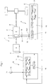
- the drive machine 4 is also assigned a control device 10, which comprises a control device 11.
- the control device 10 can be formed, for example, by a drive control which is present in any case on the vehicle, but it is also conceivable to assign the control device to the drive machine 4 separately.
- the control device 11 of the drive machine 4 is coupled to a power actuator 12 of the drive machine 4.
- the torque that can be output by the drive machine 4 can be influenced at least indirectly via the power actuator 12.
- the control takes place when a signal describing the driver's desire for increased speed or acceleration at least indirectly characterizing size is specified.
- the control device 11 for receiving a variable that at least indirectly characterizes the driver request is coupled to a device 13 for detecting or generating a signal from a variable that describes the driver request at least indirectly.
- the coupling preferably takes place directly with an actuating element 14, which is designed as an accelerator pedal and by means of which the driver's request for increased speed or acceleration can be specified.
- the control device 11 of the drive machine 4 is processed this input variable, which forms a setpoint for an acceleration and / or increase in the speed desired by the driver, for which purpose this control device has an evaluation device 15.
- This forms the setpoint for the control of the power actuator 12 of the drive machine 4 to change the torque M MA that can be output and / or the power.
- this torque M MA which corresponds to the torque that can be output on the drive machine 4
- the input torque M E applied to the gear unit 2, in particular to the converter automatic transmission 3 at the input 7, has a certain size.
- the control device 6 of the gear unit 2, in particular of the converter automatic transmission 3, has at least one input 16, here 16.1 and 16.2, which is at least indirectly coupled to the devices for detecting the speeds of the pump wheel and turbine wheel, which are designated, for example, by 17 and 18 .
- the coupling can take place in parallel, that is to say the control device 6 has a plurality of inputs 16.1 and 16.2, each of which can be coupled to a device, for example the device 17 for detecting the speed of the pump wheel or the device 18 for detecting the speed of the turbine wheel ,
- the value for the speed ratio ⁇ formed in the calculation unit 19 is assigned in an assignment device 20 to corresponding ⁇ values, which can be stored in the control device 6 in different ways.
- a direct assignment is preferably made using a table or a corresponding calculation formula.
- the level of the input torque M Ezul can then be inferred from the ⁇ values and a variable which describes, at least indirectly, the current transmission ratio present in the transmission module 2, in particular in the converter automatic transmission 3.
- the translation is preferably selected directly, which can be determined, for example, on the basis of an input signal at the control device 6 for a specific engaged gear and which is formed as a function of the gear unit according to the assignment between the engaged gear stage and the gear ratio present there.
- the actuation of the actuation elements required for a corresponding gear can be regarded as such a variable.
- the specification of the gear-dependent translation can thus be taken into account in different ways. It is conceivable to use only one signal or a plurality of signals. In order to determine the theoretically permissible input torque M E permissible, the maximum output torque M Agrenz is also required, ie the value which should under no circumstances be exceeded.
- This can either be a predefinable variable or a permanently stored one, which is predefined for the specific gear unit.
- This variable is also processed in the control device , the permissible input torque M E permissible resulting from the maximum possible output torque M AGRENZ and the product of the conversion ⁇ and the gear-dependent transmission ratio i.
- the determination is made in a further calculation unit 21, wherein the individual calculation units 20 and 19 and the assignment device 20 can be combined to form a structural unit or can be implemented by an element, for example a microprocessor unit.
- the maximum permissible input torque M E permissible is then fed to the control device 10, in particular the control device 11 of the drive machine, for example via a coupling 22, this value being regarded as a limit value for the torque M MA limit that can be output by the drive machine 4.
- the drive machine 4 is now controlled in such a way that the outputtable target torque M MAsoll resulting from the driver's request is compared with the calculated permissible input torque M E of the transmission assembly 2, taking into account any intermediate speed / torque conversion that may occur, and no changes in the control of the drive are undershot if this is undershot Drive machine 4 takes place, while if it is exceeded, an adaptation to the permissible value of the input torque M Ezul to be generated takes place at the transmission input 7.
- the controller 11 has a comparison device 23 that a comparison of theoretically calculated maximum permissible input torque to the transmission module M with which ezul adjustable in dependence on the driver's wish at the input 7 of the transmission input torque M E. It should be taken into account here that this relationship only applies to a direct coupling between the output of the drive machine 4 and the input 7 of the transmission input shaft, that is to say if no speed / torque conversion takes place in between. Otherwise, an intermediate component with regard to the power transmission must also be taken into account.
- v-value that is Speed ratio between the speed of the impeller and the Turbine wheel is measurable and determined internally in the transmission control can be, that is independent of other control devices from Gear off.
- FIG. 2 A further possibility of implementing the method according to the invention is shown in FIG. 2.
- the same reference numerals are used for the same elements.
- a quantity that at least indirectly characterizes the driver's desire for acceleration or increase in speed which can be determined, for example, from the position of the accelerator pedal, forms a setpoint for the quantity of input torque M Esoll on the transmission input shaft of the transmission assembly .
- This setpoint is either available from the control device 11 of the drive machine 4 via a so-called CAN bus, if the actuating device 14 is not directly connected to the control device 10, in particular the control device 11 of the drive machine 4, or is connected to the control device 10 in order to specify a driver request Control device 5 of the transmission assembly 2, as shown in the figure.
- the control device 6 of the transmission unit 2 continuously forms a corresponding target quantity for a torque M MA that can be output by the drive machine in such a way that the calculated limit value for the torque that can be output by the transmission unit, i.e. the output torque M A or the input torque M Epermissible at the input of the gear unit is not exceeded.
- This setpoint is supplied by the control device 6 as a setpoint to the control device of the drive machine 4, which can be done via a corresponding CAN interface.
- a setpoint for the outputable torque M MA to be generated by the drive machine is formed via the control device 6 of the gear unit and the working point in the Can field of the drive machine is determined in connection with the selection of the gear ratio.
- the speeds n T and n P required for the control can be detected directly or indirectly.
- the detection can be carried out either by appropriate devices, for example in the form of sensors directly at the corresponding measuring points or by detecting the speeds at other measuring points with a known gear ratio or by evaluating the speed transmitted via an interface, for example Can-Bus ,
- the current auxiliary power output is determined For example, from the difference between the current taps tapped by the Can bus Engine power, i.e. the power provided by the prime mover and the drive power currently transmitted via the transmission. This Difference is determined. The one based on the specific allowed Resulting input power to be provided the gear unit and the current from the auxiliary units required power is used to determine the power of the prime mover service to be provided.
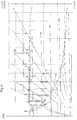
- FIG. 3 illustrates the principle of torque reduction in a M A ME control diagram.
- the characteristic curve I shown there clarifies the torque M that can theoretically be output at the output 8 of the transmission module 2, in particular the torque converter automatic transmission unit 3, while the characteristic curve II represents the characteristic curve that arises for the maximum torque M Amax that can be output at the output of the transmission module 8.
- the resulting torque at input 7 of the gear unit is characterized by characteristic curve III.
- FIG. 4 shows the tractive force curve when compared with one another during the start-up process with a solution according to the invention Control of the starting process in a drive train with a Gear unit and a conventional control of the Starting operation.
- the solution according to the invention is designated A while the conventional solution is marked with B.
Landscapes
- Engineering & Computer Science (AREA)
- Mechanical Engineering (AREA)
- Chemical & Material Sciences (AREA)
- Combustion & Propulsion (AREA)
- Transportation (AREA)
- Automation & Control Theory (AREA)
- General Engineering & Computer Science (AREA)
- Control Of Transmission Device (AREA)
Abstract
Description
- MA =
- Ausgangsdrehmoment
- ME =
- Eingangsdrehmoment
- µ =
- Wandlung
- i =
- gangabhängige Übersetzung im Getriebe
- nT =
- Turbinendrehzahl
- nP =
- Pumpendrehzahl
- Fig. 1
- verdeutlicht in schematisch vereinfachter Darstellung anhand eines Blockschaltbildes eine erste mögliche Ausführung des erfindungsgemäßen Verfahrens;
- Fig. 2
- verdeutlicht anhand eines Blockschaltbildes eine zweite Variante des erfindungsgemäßen Verfahrens;
- Fig. 3
- verdeutlicht anhand eines Diagrammes den Verlauf der Drehmomentaufnahme;
- Fig. 4
- verdeutlicht anhand eines Diagrammes den mit dem erfindungsgemäßen Verfahren sich einstellenden Zugkraftverlauf.
- MA -
- Ausgangsdrehmoment
- ME -
- Eingangsdrehmoment
- µ -
- Wandlung
- i -
- gangabhängige Übersetzung im Getriebe
- MAGRENz -
- nicht zu überschreitender Vorgabewert für Ausgangsdrehmoment
- ν -
- Drehzahlverhältnis
- nT-
- Turbinendrehzahl
- nP -
- Pumpendrehzahl des hydrodynamischen Drehzahl/Drehmomentwandlers des Wandlerautomatgetriebes 3
- 1
- Antriebsstrang
- 2
- Getriebebaueinheit
- 3
- Wandlerautomatgetriebe
- 4
- Antriebsmaschine
- 5
- Steuervorrichtung
- 6
- Steuereinrichtung
- 7
- Eingang
- 8
- Ausgang
- 9
- Wandler
- 10
- Steuervorrichtung der Antriebsmaschine
- 11
- Steuereinrichtung der Antriebsmaschine
- 12
- Leistungsstellglied
- 13
- Einrichtung zur Erfassung einer den Fahrerwunsch wenigstens mittelbar charakterisierenden Größe
- 14
- Betätigungseinrichtung
- 15
- Auswerteinrichtung der Steuereinrichtung der Antriebsmaschine
- 16
- Eingang der Steuereinrichtung der Getriebebaueinheit
- 17
- Einrichtung zur Erfassung der Drehzahl des Pumpenrades
- 18
- Einrichtung zur Erfassung der Drehzahl des Turbinenrades
- 19
- Berechnungseinheit
- 20
- Zuordnungseinrichtung
- 21
- Berechnungseinheit
- 22
- Kopplung
- 23
- Vergleichseinrichtung
- MA
- Ausgangsdrehmoment
- ME
- Eingangsdrehmoment
- MMAsoll
- Abgebbares Sollmoment der Antriebsmaschine
- MEzulässig
- Zulässiges Eingangsdrehmoment
- MMA
- Abgebbares Moment an der Antriebsmaschine
- MAist
- Istwert des Ausgangsdrehmomentes
- MEsoll - W
- sich ergebender Sollwert für Eingangsdrehmoment aufgrund Fahrerwunsch
Claims (6)
- Verfahren zur Steuerung des Anfahrvorganges in einem Antriebssystem für Fahrzeuge, umfassend eine Antriebsmaschine und eine mit dieser koppelbaren und wenigstens zwei Gangstufen umfassenden Getriebebaueinheit, welche wenigstens einen hydrodynamischen Getriebeteil umfasst;
gekennzeichnet durch das folgende Merkmal:1.1 bei welchem unter Berücksichtigung der Übersetzung der aktuellen Gangstufe das an der Eingangswelle der Getriebebaueinheit anliegende Eingangsdrehmoment derart gesteuert wird, daß ein bestimmter vordefinierbarer Grenzwert für das am Ausgang der Getriebebaueinheit anliegende Ausgangsmoment nicht überschritten wird. - Verfahren nach Anspruch 1, gekennzeichnet durch die folgenden Merkmale:2.1 bei welchem das zulässige Eingangsdrehmoment am Eingang der Getriebebaueinheit aus dem Quotienten des vorgebbaren maximalen Ausgangsdrehmomentes der Getriebebaueinheit und dem Produkt der Wandlung mit der Übersetzung der aktuellen Gangstufe gebildet wird, wobei der Wert für die Wandlung wenigstens mittelbar, vorzugsweise direkt, durch die Drehzahlen des Pumpen- und Turbinenrades charakterisiert sind.
- Verfahren nach Anspruch 2, dadurch gekennzeichnet, daß bei Vorgabe eines, den Fahrerwunsch nach Beschleunigung, Verzögerung oder einer bestimmten definierten Geschwindigkeit wenigstens mittelbar charakterisierenden Größe aus diesem einen Sollwert für ein an der Antriebsmaschine abgebbares Moment gebildet wird, wobei dieser Sollwert proportional zum an der Getriebeingangswelle anliegenden Eingangsmoment ist oder unter Berücksichtigung der an den Nebenverbrauchern erforderlichen Leistung gebildet wird und bei welchem aus dem berechneten zulässigen Eingangsdrehmoment ein Sollwert für das aktuelle von der Antriebsmaschine abzugebene Moment gebildet wird, wobei in einer der Antriebsmaschine zugeordneten Steuerung die beiden Sollwertvorgaben verglichen werden und bei Überschreitung des von der Getriebesteuerung gebildeten Sollwertes durch das vom Fahrer vorgegebene Moment der von der Getriebesteuerung vorgegebene Sollwert als maximales abzugebendes Moment gesetzt wird.
- Verfahren nach einem der Ansprüche 1 oder 2, dadurch gekennzeichnet, daß ein, dem Fahrerwunsch nach Beschleunigung, Verzögerung oder Änderung der Geschwindigkeit wenigstens mittelbar charakterisierende Größe an einer der Getriebebaueinheit zugeordneten Steuervorrichtung einen Sollwert für das von der Antriebsmaschine abzugebende Moment bildet, wobei dieser Sollwert in der Getriebesteuervorrichtung mit dem berechneten maximal zulässigen Eingangsmoment verglichen wird, wobei die Sollwertvorgabe in Abhängigkeit des Vergleiches an die Motorsteuerung erfolgt.
- Verfahren nach einem der Ansprüche 1 bis 4, dadurch gekennzeichnet, daß neben dem zulässigen Eingangsmoment eine weitere zweite Größe in der Steuerung berücksichtigt wird.
- Verfahren nach einem der Ansprüche 1 bis 5, dadurch gekennzeichnet, daß für eine bestimmte Zeitdauer eine Überschreitung des maxial zulässigen Ausgangsdrehmomentes vorgesehen ist.
Applications Claiming Priority (2)
| Application Number | Priority Date | Filing Date | Title |
|---|---|---|---|
| DE10045648 | 2000-09-15 | ||
| DE10045648A DE10045648A1 (de) | 2000-09-15 | 2000-09-15 | Regelung/Begrenzung des Eingangsmomentes eines Getriebes während des Anfahrvorgangs |
Publications (2)
| Publication Number | Publication Date |
|---|---|
| EP1188601A1 true EP1188601A1 (de) | 2002-03-20 |
| EP1188601B1 EP1188601B1 (de) | 2005-10-19 |
Family
ID=7656306
Family Applications (1)
| Application Number | Title | Priority Date | Filing Date |
|---|---|---|---|
| EP01120311A Expired - Lifetime EP1188601B1 (de) | 2000-09-15 | 2001-08-24 | Regelung/Begrenzung des Eingangsmomentes eines Getriebes während des Anfahrvorgangs |
Country Status (3)
| Country | Link |
|---|---|
| EP (1) | EP1188601B1 (de) |
| AT (1) | ATE307039T1 (de) |
| DE (2) | DE10045648A1 (de) |
Cited By (2)
| Publication number | Priority date | Publication date | Assignee | Title |
|---|---|---|---|---|
| EP1602522A1 (de) * | 2004-06-03 | 2005-12-07 | Zf Friedrichshafen Ag | Verfahren zur optimierten Erfassung des Getriebeeingangsmomentes in Fahrzeugen, die mit motorseitigen Nebenaggregaten ausgestattet sind |
| WO2007020037A1 (de) * | 2005-08-16 | 2007-02-22 | Voith Turbo Gmbh & Co. Kg | Antriebssystem für den einsatz in fahrzeugen und verfahren zur optimierung des anfahrvorganges in fahrzeugen |
Families Citing this family (2)
| Publication number | Priority date | Publication date | Assignee | Title |
|---|---|---|---|---|
| DE102005004224A1 (de) * | 2005-01-28 | 2006-08-10 | Voith Turbo Gmbh & Co. Kg | Verfahren zur Steuerung des Anfahrvorganges in einem Antriebsstrang eines Fahrzeuges |
| DE102013112968A1 (de) * | 2013-11-25 | 2015-05-28 | Dr. Ing. H.C. F. Porsche Ag | Verfahren zum Steuern eines Verbrennungsmotors |
Citations (11)
| Publication number | Priority date | Publication date | Assignee | Title |
|---|---|---|---|---|
| DE3735246A1 (de) * | 1986-10-31 | 1988-05-05 | Zahnradfabrik Friedrichshafen | Antriebseinrichtung fuer ein kraftfahrzeug |
| US5065319A (en) * | 1989-12-12 | 1991-11-12 | Toyota Jidosha Kabushiki Kaisha | Power control system for vehicles |
| EP0512726A2 (de) * | 1991-05-09 | 1992-11-11 | Eaton Corporation | Strategie zur Steuerung der Antriebstrang-Drehmomentbegrenzung unter Verwendung einer Motorsteuerung |
| EP0524667A2 (de) * | 1991-06-07 | 1993-01-27 | General Motors Corporation | Methode und Vorrichtung zur Regelung des Auflader-Ladedrucks |
| DE9314512U1 (de) * | 1993-09-24 | 1993-11-11 | Siemens AG, 80333 München | Sicherheitseinrichtung an einem Kraftfahrzeug mit einem automatischen Getriebe |
| EP0833042A2 (de) * | 1996-09-30 | 1998-04-01 | Cummins Engine Company, Inc. | Ausgangsdrehmoment-Steuerungssystem und Verfahren für eine Brennkraftmaschine |
| EP0937602A1 (de) * | 1998-02-20 | 1999-08-25 | Eaton Corporation | Steuerung des Motorschwungraddrehmoments |
| DE19844618A1 (de) * | 1998-09-29 | 2000-03-30 | Zahnradfabrik Friedrichshafen | Verfahren zur Reduzierung der thermischen Belastung eines Automatgetriebes für ein Kraftfahrzeug in einem Notfahrbetrieb |
| US6064934A (en) * | 1996-03-26 | 2000-05-16 | Robert Bosch Gmbh | Process and device for regulating the torque derived from a drive unit |
| FR2785961A1 (fr) * | 1998-11-12 | 2000-05-19 | Renault | Vehicule automobile comportant une boite de vitesses a changements de rapports automatises |
| DE19950664A1 (de) * | 1999-10-21 | 2001-04-26 | Zahnradfabrik Friedrichshafen | Verfahren zur Steuerung eines Automatgetriebes, insbesondere Stufenautomatgetriebes, für ein Kraftfahrzeug |
Family Cites Families (1)
| Publication number | Priority date | Publication date | Assignee | Title |
|---|---|---|---|---|
| DE19726194A1 (de) * | 1997-06-20 | 1998-12-24 | Bayerische Motoren Werke Ag | Verfahren zur Beeinflussung des Drehmoments einer Brennkraftmaschine |
-
2000
- 2000-09-15 DE DE10045648A patent/DE10045648A1/de not_active Ceased
-
2001
- 2001-08-24 AT AT01120311T patent/ATE307039T1/de not_active IP Right Cessation
- 2001-08-24 DE DE50107740T patent/DE50107740D1/de not_active Expired - Lifetime
- 2001-08-24 EP EP01120311A patent/EP1188601B1/de not_active Expired - Lifetime
Patent Citations (11)
| Publication number | Priority date | Publication date | Assignee | Title |
|---|---|---|---|---|
| DE3735246A1 (de) * | 1986-10-31 | 1988-05-05 | Zahnradfabrik Friedrichshafen | Antriebseinrichtung fuer ein kraftfahrzeug |
| US5065319A (en) * | 1989-12-12 | 1991-11-12 | Toyota Jidosha Kabushiki Kaisha | Power control system for vehicles |
| EP0512726A2 (de) * | 1991-05-09 | 1992-11-11 | Eaton Corporation | Strategie zur Steuerung der Antriebstrang-Drehmomentbegrenzung unter Verwendung einer Motorsteuerung |
| EP0524667A2 (de) * | 1991-06-07 | 1993-01-27 | General Motors Corporation | Methode und Vorrichtung zur Regelung des Auflader-Ladedrucks |
| DE9314512U1 (de) * | 1993-09-24 | 1993-11-11 | Siemens AG, 80333 München | Sicherheitseinrichtung an einem Kraftfahrzeug mit einem automatischen Getriebe |
| US6064934A (en) * | 1996-03-26 | 2000-05-16 | Robert Bosch Gmbh | Process and device for regulating the torque derived from a drive unit |
| EP0833042A2 (de) * | 1996-09-30 | 1998-04-01 | Cummins Engine Company, Inc. | Ausgangsdrehmoment-Steuerungssystem und Verfahren für eine Brennkraftmaschine |
| EP0937602A1 (de) * | 1998-02-20 | 1999-08-25 | Eaton Corporation | Steuerung des Motorschwungraddrehmoments |
| DE19844618A1 (de) * | 1998-09-29 | 2000-03-30 | Zahnradfabrik Friedrichshafen | Verfahren zur Reduzierung der thermischen Belastung eines Automatgetriebes für ein Kraftfahrzeug in einem Notfahrbetrieb |
| FR2785961A1 (fr) * | 1998-11-12 | 2000-05-19 | Renault | Vehicule automobile comportant une boite de vitesses a changements de rapports automatises |
| DE19950664A1 (de) * | 1999-10-21 | 2001-04-26 | Zahnradfabrik Friedrichshafen | Verfahren zur Steuerung eines Automatgetriebes, insbesondere Stufenautomatgetriebes, für ein Kraftfahrzeug |
Cited By (2)
| Publication number | Priority date | Publication date | Assignee | Title |
|---|---|---|---|---|
| EP1602522A1 (de) * | 2004-06-03 | 2005-12-07 | Zf Friedrichshafen Ag | Verfahren zur optimierten Erfassung des Getriebeeingangsmomentes in Fahrzeugen, die mit motorseitigen Nebenaggregaten ausgestattet sind |
| WO2007020037A1 (de) * | 2005-08-16 | 2007-02-22 | Voith Turbo Gmbh & Co. Kg | Antriebssystem für den einsatz in fahrzeugen und verfahren zur optimierung des anfahrvorganges in fahrzeugen |
Also Published As
| Publication number | Publication date |
|---|---|
| DE50107740D1 (de) | 2005-11-24 |
| EP1188601B1 (de) | 2005-10-19 |
| ATE307039T1 (de) | 2005-11-15 |
| DE10045648A1 (de) | 2002-04-04 |
Similar Documents
| Publication | Publication Date | Title |
|---|---|---|
| EP1448403B1 (de) | System und verfahren zur vorgabe eines motordrehmomentes und einer getriebeübersetzung bei einem fahrzeug mit kontinuierlich verstellbarem getriebe | |
| DE10143735C1 (de) | Verfahren zum Entlasten des Fahrers eines Kraftfahrzeuges und Vorrichtung zur Geschwindigkeitsregelung eines Kraftfahrzeuges | |
| EP1047889B1 (de) | Verfahren zur steuerung eines schaltvorganges in automatikgetrieben | |
| WO2010145863A1 (de) | Verfahren und vorrichtung zur bestimmung des beginns einer startphase eines verbrennungsmotors in einem hybridfahrzeug | |
| EP0584457A1 (de) | Verfahren und Vorrichtung zur geregelten Zu- und Abkopplung der Fahrkupplung im Getriebe eines Fahrzeuges | |
| EP1108922B1 (de) | Verfahren und Vorrichtung zur Steuerung eines stufenlosen Automatikgetriebes | |
| EP2193061B1 (de) | Verfahren und vorrichtung zur beeinflussung der zugkraft während schaltvorgängen eines schaltgetriebes bei fahrzeugen | |
| EP1188601B1 (de) | Regelung/Begrenzung des Eingangsmomentes eines Getriebes während des Anfahrvorgangs | |
| EP3873763A1 (de) | Verfahren und antriebssteuergerät zum betrieb von zumindest zwei elektrischen antriebsmaschinen bei einer laständerung sowie kraftfahrzeug mit einem antriebssteuergrät | |
| WO2010112257A1 (de) | Verfahren und vorrichtung zum betreiben eines hybridfahrzeuges | |
| WO2011147616A1 (de) | Verfahren zum betreiben eines antriebsstrangs | |
| EP2271534A1 (de) | Verfahren zur steuerung eines dualen pumpsystems in hybridantrieben | |
| EP2310717B1 (de) | Verfahren zum betrieb eines drehmomentübertragungssystems und drehmomentübertragungssystem | |
| EP2813734B1 (de) | Verfahren und Vorrichtung zur Steuerung eines Schaltgetriebes | |
| WO2000006410A1 (de) | Verfahren und vorrichtung zur steuerung der geschwindigkeit eines fahrzeugs | |
| DE102005004224A1 (de) | Verfahren zur Steuerung des Anfahrvorganges in einem Antriebsstrang eines Fahrzeuges | |
| EP4168264B1 (de) | Verfahren zur steuerung eines hybridantriebssystems für ein kraftfahrzeug | |
| DE3800372C2 (de) | Steuereinrichtung zur Bremsung eines Fahrzeuges | |
| DE19946905B4 (de) | Antriebsschlupfregelsystem | |
| DE10065725A1 (de) | Verfahren zum Betreiben eines Antriebsstrangs eines Kraftfahrzeugs und Regelungseinrichtung zur Durchführung des Verfahrens | |
| DE102007022812A1 (de) | Verfahren zur Begrenzung des Eingangsmoments an einer Getriebeeinheit und Steuerungssystem | |
| EP0976604B1 (de) | Verfahren zur Beeinflussung des Drehmoments einer Brennkraftmaschine | |
| WO2020148361A1 (de) | Verfahren und steuereinheit zum betrieb eines lastschaltbaren getriebes | |
| DE10305180A1 (de) | Verfahren zum Steuern und Regeln eines Sollverlaufs eines zeitlich veränderlichen Signals eines Systems | |
| DE10137475C1 (de) | Verfahren zur Steuerung des Eingangsmoments an einer Getriebebaueinheit |
Legal Events
| Date | Code | Title | Description |
|---|---|---|---|
| PUAI | Public reference made under article 153(3) epc to a published international application that has entered the european phase |
Free format text: ORIGINAL CODE: 0009012 |
|
| AK | Designated contracting states |
Kind code of ref document: A1 Designated state(s): AT BE CH CY DE DK ES FI FR GB GR IE IT LI LU MC NL PT SE TR |
|
| AX | Request for extension of the european patent |
Free format text: AL;LT;LV;MK;RO;SI |
|
| 17P | Request for examination filed |
Effective date: 20020607 |
|
| 17Q | First examination report despatched |
Effective date: 20020807 |
|
| AKX | Designation fees paid |
Free format text: AT BE CH CY DE DK ES FI FR GB GR IE IT LI LU MC NL PT SE TR |
|
| GRAP | Despatch of communication of intention to grant a patent |
Free format text: ORIGINAL CODE: EPIDOSNIGR1 |
|
| GRAS | Grant fee paid |
Free format text: ORIGINAL CODE: EPIDOSNIGR3 |
|
| GRAA | (expected) grant |
Free format text: ORIGINAL CODE: 0009210 |
|
| AK | Designated contracting states |
Kind code of ref document: B1 Designated state(s): AT BE CH CY DE DK ES FI FR GB GR IE IT LI LU MC NL PT SE TR |
|
| PG25 | Lapsed in a contracting state [announced via postgrant information from national office to epo] |
Ref country code: IT Free format text: LAPSE BECAUSE OF FAILURE TO SUBMIT A TRANSLATION OF THE DESCRIPTION OR TO PAY THE FEE WITHIN THE PRESCRIBED TIME-LIMIT;WARNING: LAPSES OF ITALIAN PATENTS WITH EFFECTIVE DATE BEFORE 2007 MAY HAVE OCCURRED AT ANY TIME BEFORE 2007. THE CORRECT EFFECTIVE DATE MAY BE DIFFERENT FROM THE ONE RECORDED. Effective date: 20051019 Ref country code: FI Free format text: LAPSE BECAUSE OF FAILURE TO SUBMIT A TRANSLATION OF THE DESCRIPTION OR TO PAY THE FEE WITHIN THE PRESCRIBED TIME-LIMIT Effective date: 20051019 Ref country code: NL Free format text: LAPSE BECAUSE OF FAILURE TO SUBMIT A TRANSLATION OF THE DESCRIPTION OR TO PAY THE FEE WITHIN THE PRESCRIBED TIME-LIMIT Effective date: 20051019 Ref country code: IE Free format text: LAPSE BECAUSE OF FAILURE TO SUBMIT A TRANSLATION OF THE DESCRIPTION OR TO PAY THE FEE WITHIN THE PRESCRIBED TIME-LIMIT Effective date: 20051019 Ref country code: GB Free format text: LAPSE BECAUSE OF FAILURE TO SUBMIT A TRANSLATION OF THE DESCRIPTION OR TO PAY THE FEE WITHIN THE PRESCRIBED TIME-LIMIT Effective date: 20051019 |
|
| REG | Reference to a national code |
Ref country code: GB Ref legal event code: FG4D Free format text: NOT ENGLISH |
|
| REG | Reference to a national code |
Ref country code: CH Ref legal event code: EP |
|
| REG | Reference to a national code |
Ref country code: IE Ref legal event code: FG4D Free format text: LANGUAGE OF EP DOCUMENT: GERMAN |
|
| REF | Corresponds to: |
Ref document number: 50107740 Country of ref document: DE Date of ref document: 20051124 Kind code of ref document: P |
|
| PG25 | Lapsed in a contracting state [announced via postgrant information from national office to epo] |
Ref country code: SE Free format text: LAPSE BECAUSE OF FAILURE TO SUBMIT A TRANSLATION OF THE DESCRIPTION OR TO PAY THE FEE WITHIN THE PRESCRIBED TIME-LIMIT Effective date: 20060119 Ref country code: GR Free format text: LAPSE BECAUSE OF FAILURE TO SUBMIT A TRANSLATION OF THE DESCRIPTION OR TO PAY THE FEE WITHIN THE PRESCRIBED TIME-LIMIT Effective date: 20060119 Ref country code: DK Free format text: LAPSE BECAUSE OF FAILURE TO SUBMIT A TRANSLATION OF THE DESCRIPTION OR TO PAY THE FEE WITHIN THE PRESCRIBED TIME-LIMIT Effective date: 20060119 |
|
| PG25 | Lapsed in a contracting state [announced via postgrant information from national office to epo] |
Ref country code: ES Free format text: LAPSE BECAUSE OF FAILURE TO SUBMIT A TRANSLATION OF THE DESCRIPTION OR TO PAY THE FEE WITHIN THE PRESCRIBED TIME-LIMIT Effective date: 20060130 |
|
| PG25 | Lapsed in a contracting state [announced via postgrant information from national office to epo] |
Ref country code: PT Free format text: LAPSE BECAUSE OF FAILURE TO SUBMIT A TRANSLATION OF THE DESCRIPTION OR TO PAY THE FEE WITHIN THE PRESCRIBED TIME-LIMIT Effective date: 20060320 |
|
| NLV1 | Nl: lapsed or annulled due to failure to fulfill the requirements of art. 29p and 29m of the patents act | ||
| GBV | Gb: ep patent (uk) treated as always having been void in accordance with gb section 77(7)/1977 [no translation filed] |
Effective date: 20051019 |
|
| REG | Reference to a national code |
Ref country code: IE Ref legal event code: FD4D |
|
| PLBE | No opposition filed within time limit |
Free format text: ORIGINAL CODE: 0009261 |
|
| STAA | Information on the status of an ep patent application or granted ep patent |
Free format text: STATUS: NO OPPOSITION FILED WITHIN TIME LIMIT |
|
| PG25 | Lapsed in a contracting state [announced via postgrant information from national office to epo] |
Ref country code: MC Free format text: LAPSE BECAUSE OF NON-PAYMENT OF DUE FEES Effective date: 20060831 Ref country code: BE Free format text: LAPSE BECAUSE OF NON-PAYMENT OF DUE FEES Effective date: 20060831 Ref country code: CH Free format text: LAPSE BECAUSE OF NON-PAYMENT OF DUE FEES Effective date: 20060831 Ref country code: LI Free format text: LAPSE BECAUSE OF NON-PAYMENT OF DUE FEES Effective date: 20060831 |
|
| 26N | No opposition filed |
Effective date: 20060720 |
|
| EN | Fr: translation not filed | ||
| PG25 | Lapsed in a contracting state [announced via postgrant information from national office to epo] |
Ref country code: FR Free format text: LAPSE BECAUSE OF FAILURE TO SUBMIT A TRANSLATION OF THE DESCRIPTION OR TO PAY THE FEE WITHIN THE PRESCRIBED TIME-LIMIT Effective date: 20061208 |
|
| REG | Reference to a national code |
Ref country code: CH Ref legal event code: PL |
|
| PG25 | Lapsed in a contracting state [announced via postgrant information from national office to epo] |
Ref country code: AT Free format text: LAPSE BECAUSE OF NON-PAYMENT OF DUE FEES Effective date: 20060824 |
|
| BERE | Be: lapsed |
Owner name: VOITH TURBO G.M.B.H. & CO. KG Effective date: 20060831 |
|
| PG25 | Lapsed in a contracting state [announced via postgrant information from national office to epo] |
Ref country code: LU Free format text: LAPSE BECAUSE OF NON-PAYMENT OF DUE FEES Effective date: 20060824 Ref country code: TR Free format text: LAPSE BECAUSE OF FAILURE TO SUBMIT A TRANSLATION OF THE DESCRIPTION OR TO PAY THE FEE WITHIN THE PRESCRIBED TIME-LIMIT Effective date: 20051019 |
|
| PG25 | Lapsed in a contracting state [announced via postgrant information from national office to epo] |
Ref country code: FR Free format text: LAPSE BECAUSE OF FAILURE TO SUBMIT A TRANSLATION OF THE DESCRIPTION OR TO PAY THE FEE WITHIN THE PRESCRIBED TIME-LIMIT Effective date: 20051019 Ref country code: CY Free format text: LAPSE BECAUSE OF FAILURE TO SUBMIT A TRANSLATION OF THE DESCRIPTION OR TO PAY THE FEE WITHIN THE PRESCRIBED TIME-LIMIT Effective date: 20051019 |
|
| PGFP | Annual fee paid to national office [announced via postgrant information from national office to epo] |
Ref country code: DE Payment date: 20130827 Year of fee payment: 13 |
|
| REG | Reference to a national code |
Ref country code: DE Ref legal event code: R119 Ref document number: 50107740 Country of ref document: DE |
|
| REG | Reference to a national code |
Ref country code: DE Ref legal event code: R079 Ref document number: 50107740 Country of ref document: DE Free format text: PREVIOUS MAIN CLASS: B60K0041060000 Ipc: B60W0030180000 |
|
| PG25 | Lapsed in a contracting state [announced via postgrant information from national office to epo] |
Ref country code: DE Free format text: LAPSE BECAUSE OF NON-PAYMENT OF DUE FEES Effective date: 20150303 |