EP1188511A2 - Machine tool with a motor driven tool slide - Google Patents
Machine tool with a motor driven tool slide Download PDFInfo
- Publication number
- EP1188511A2 EP1188511A2 EP01120685A EP01120685A EP1188511A2 EP 1188511 A2 EP1188511 A2 EP 1188511A2 EP 01120685 A EP01120685 A EP 01120685A EP 01120685 A EP01120685 A EP 01120685A EP 1188511 A2 EP1188511 A2 EP 1188511A2
- Authority
- EP
- European Patent Office
- Prior art keywords
- machine tool
- tool according
- machine
- processing unit
- cross
- Prior art date
- Legal status (The legal status is an assumption and is not a legal conclusion. Google has not performed a legal analysis and makes no representation as to the accuracy of the status listed.)
- Granted
Links
Images


Classifications
-
- B—PERFORMING OPERATIONS; TRANSPORTING
- B23—MACHINE TOOLS; METAL-WORKING NOT OTHERWISE PROVIDED FOR
- B23Q—DETAILS, COMPONENTS, OR ACCESSORIES FOR MACHINE TOOLS, e.g. ARRANGEMENTS FOR COPYING OR CONTROLLING; MACHINE TOOLS IN GENERAL CHARACTERISED BY THE CONSTRUCTION OF PARTICULAR DETAILS OR COMPONENTS; COMBINATIONS OR ASSOCIATIONS OF METAL-WORKING MACHINES, NOT DIRECTED TO A PARTICULAR RESULT
- B23Q3/00—Devices holding, supporting, or positioning work or tools, of a kind normally removable from the machine
- B23Q3/155—Arrangements for automatic insertion or removal of tools, e.g. combined with manual handling
- B23Q3/157—Arrangements for automatic insertion or removal of tools, e.g. combined with manual handling of rotary tools
- B23Q3/15786—Arrangements for automatic insertion or removal of tools, e.g. combined with manual handling of rotary tools a plurality of tools being inserted simultaneously in a plurality of spindles directly from a storage device, i.e. without using transfer devices
-
- B—PERFORMING OPERATIONS; TRANSPORTING
- B23—MACHINE TOOLS; METAL-WORKING NOT OTHERWISE PROVIDED FOR
- B23Q—DETAILS, COMPONENTS, OR ACCESSORIES FOR MACHINE TOOLS, e.g. ARRANGEMENTS FOR COPYING OR CONTROLLING; MACHINE TOOLS IN GENERAL CHARACTERISED BY THE CONSTRUCTION OF PARTICULAR DETAILS OR COMPONENTS; COMBINATIONS OR ASSOCIATIONS OF METAL-WORKING MACHINES, NOT DIRECTED TO A PARTICULAR RESULT
- B23Q1/00—Members which are comprised in the general build-up of a form of machine, particularly relatively large fixed members
- B23Q1/01—Frames, beds, pillars or like members; Arrangement of ways
- B23Q1/012—Portals
-
- B—PERFORMING OPERATIONS; TRANSPORTING
- B23—MACHINE TOOLS; METAL-WORKING NOT OTHERWISE PROVIDED FOR
- B23Q—DETAILS, COMPONENTS, OR ACCESSORIES FOR MACHINE TOOLS, e.g. ARRANGEMENTS FOR COPYING OR CONTROLLING; MACHINE TOOLS IN GENERAL CHARACTERISED BY THE CONSTRUCTION OF PARTICULAR DETAILS OR COMPONENTS; COMBINATIONS OR ASSOCIATIONS OF METAL-WORKING MACHINES, NOT DIRECTED TO A PARTICULAR RESULT
- B23Q1/00—Members which are comprised in the general build-up of a form of machine, particularly relatively large fixed members
- B23Q1/01—Frames, beds, pillars or like members; Arrangement of ways
- B23Q1/015—Frames, beds, pillars
-
- B—PERFORMING OPERATIONS; TRANSPORTING
- B23—MACHINE TOOLS; METAL-WORKING NOT OTHERWISE PROVIDED FOR
- B23Q—DETAILS, COMPONENTS, OR ACCESSORIES FOR MACHINE TOOLS, e.g. ARRANGEMENTS FOR COPYING OR CONTROLLING; MACHINE TOOLS IN GENERAL CHARACTERISED BY THE CONSTRUCTION OF PARTICULAR DETAILS OR COMPONENTS; COMBINATIONS OR ASSOCIATIONS OF METAL-WORKING MACHINES, NOT DIRECTED TO A PARTICULAR RESULT
- B23Q1/00—Members which are comprised in the general build-up of a form of machine, particularly relatively large fixed members
- B23Q1/25—Movable or adjustable work or tool supports
- B23Q1/44—Movable or adjustable work or tool supports using particular mechanisms
- B23Q1/50—Movable or adjustable work or tool supports using particular mechanisms with rotating pairs only, the rotating pairs being the first two elements of the mechanism
- B23Q1/54—Movable or adjustable work or tool supports using particular mechanisms with rotating pairs only, the rotating pairs being the first two elements of the mechanism two rotating pairs only
- B23Q1/5406—Movable or adjustable work or tool supports using particular mechanisms with rotating pairs only, the rotating pairs being the first two elements of the mechanism two rotating pairs only a single rotating pair followed perpendicularly by a single rotating pair
-
- B—PERFORMING OPERATIONS; TRANSPORTING
- B23—MACHINE TOOLS; METAL-WORKING NOT OTHERWISE PROVIDED FOR
- B23Q—DETAILS, COMPONENTS, OR ACCESSORIES FOR MACHINE TOOLS, e.g. ARRANGEMENTS FOR COPYING OR CONTROLLING; MACHINE TOOLS IN GENERAL CHARACTERISED BY THE CONSTRUCTION OF PARTICULAR DETAILS OR COMPONENTS; COMBINATIONS OR ASSOCIATIONS OF METAL-WORKING MACHINES, NOT DIRECTED TO A PARTICULAR RESULT
- B23Q1/00—Members which are comprised in the general build-up of a form of machine, particularly relatively large fixed members
- B23Q1/25—Movable or adjustable work or tool supports
- B23Q1/44—Movable or adjustable work or tool supports using particular mechanisms
- B23Q1/50—Movable or adjustable work or tool supports using particular mechanisms with rotating pairs only, the rotating pairs being the first two elements of the mechanism
- B23Q1/54—Movable or adjustable work or tool supports using particular mechanisms with rotating pairs only, the rotating pairs being the first two elements of the mechanism two rotating pairs only
- B23Q1/5468—Movable or adjustable work or tool supports using particular mechanisms with rotating pairs only, the rotating pairs being the first two elements of the mechanism two rotating pairs only a single rotating pair followed parallelly by a single rotating pair
-
- B—PERFORMING OPERATIONS; TRANSPORTING
- B23—MACHINE TOOLS; METAL-WORKING NOT OTHERWISE PROVIDED FOR
- B23Q—DETAILS, COMPONENTS, OR ACCESSORIES FOR MACHINE TOOLS, e.g. ARRANGEMENTS FOR COPYING OR CONTROLLING; MACHINE TOOLS IN GENERAL CHARACTERISED BY THE CONSTRUCTION OF PARTICULAR DETAILS OR COMPONENTS; COMBINATIONS OR ASSOCIATIONS OF METAL-WORKING MACHINES, NOT DIRECTED TO A PARTICULAR RESULT
- B23Q1/00—Members which are comprised in the general build-up of a form of machine, particularly relatively large fixed members
- B23Q1/25—Movable or adjustable work or tool supports
- B23Q1/44—Movable or adjustable work or tool supports using particular mechanisms
- B23Q1/56—Movable or adjustable work or tool supports using particular mechanisms with sliding pairs only, the sliding pairs being the first two elements of the mechanism
- B23Q1/60—Movable or adjustable work or tool supports using particular mechanisms with sliding pairs only, the sliding pairs being the first two elements of the mechanism two sliding pairs only, the sliding pairs being the first two elements of the mechanism
- B23Q1/62—Movable or adjustable work or tool supports using particular mechanisms with sliding pairs only, the sliding pairs being the first two elements of the mechanism two sliding pairs only, the sliding pairs being the first two elements of the mechanism with perpendicular axes, e.g. cross-slides
- B23Q1/621—Movable or adjustable work or tool supports using particular mechanisms with sliding pairs only, the sliding pairs being the first two elements of the mechanism two sliding pairs only, the sliding pairs being the first two elements of the mechanism with perpendicular axes, e.g. cross-slides a single sliding pair followed perpendicularly by a single sliding pair
- B23Q1/623—Movable or adjustable work or tool supports using particular mechanisms with sliding pairs only, the sliding pairs being the first two elements of the mechanism two sliding pairs only, the sliding pairs being the first two elements of the mechanism with perpendicular axes, e.g. cross-slides a single sliding pair followed perpendicularly by a single sliding pair followed perpendicularly by a single rotating pair
-
- B—PERFORMING OPERATIONS; TRANSPORTING
- B23—MACHINE TOOLS; METAL-WORKING NOT OTHERWISE PROVIDED FOR
- B23Q—DETAILS, COMPONENTS, OR ACCESSORIES FOR MACHINE TOOLS, e.g. ARRANGEMENTS FOR COPYING OR CONTROLLING; MACHINE TOOLS IN GENERAL CHARACTERISED BY THE CONSTRUCTION OF PARTICULAR DETAILS OR COMPONENTS; COMBINATIONS OR ASSOCIATIONS OF METAL-WORKING MACHINES, NOT DIRECTED TO A PARTICULAR RESULT
- B23Q1/00—Members which are comprised in the general build-up of a form of machine, particularly relatively large fixed members
- B23Q1/25—Movable or adjustable work or tool supports
- B23Q1/44—Movable or adjustable work or tool supports using particular mechanisms
- B23Q1/56—Movable or adjustable work or tool supports using particular mechanisms with sliding pairs only, the sliding pairs being the first two elements of the mechanism
- B23Q1/60—Movable or adjustable work or tool supports using particular mechanisms with sliding pairs only, the sliding pairs being the first two elements of the mechanism two sliding pairs only, the sliding pairs being the first two elements of the mechanism
- B23Q1/62—Movable or adjustable work or tool supports using particular mechanisms with sliding pairs only, the sliding pairs being the first two elements of the mechanism two sliding pairs only, the sliding pairs being the first two elements of the mechanism with perpendicular axes, e.g. cross-slides
- B23Q1/621—Movable or adjustable work or tool supports using particular mechanisms with sliding pairs only, the sliding pairs being the first two elements of the mechanism two sliding pairs only, the sliding pairs being the first two elements of the mechanism with perpendicular axes, e.g. cross-slides a single sliding pair followed perpendicularly by a single sliding pair
- B23Q1/628—Movable or adjustable work or tool supports using particular mechanisms with sliding pairs only, the sliding pairs being the first two elements of the mechanism two sliding pairs only, the sliding pairs being the first two elements of the mechanism with perpendicular axes, e.g. cross-slides a single sliding pair followed perpendicularly by a single sliding pair followed parallelly by a single sliding pair
-
- B—PERFORMING OPERATIONS; TRANSPORTING
- B23—MACHINE TOOLS; METAL-WORKING NOT OTHERWISE PROVIDED FOR
- B23Q—DETAILS, COMPONENTS, OR ACCESSORIES FOR MACHINE TOOLS, e.g. ARRANGEMENTS FOR COPYING OR CONTROLLING; MACHINE TOOLS IN GENERAL CHARACTERISED BY THE CONSTRUCTION OF PARTICULAR DETAILS OR COMPONENTS; COMBINATIONS OR ASSOCIATIONS OF METAL-WORKING MACHINES, NOT DIRECTED TO A PARTICULAR RESULT
- B23Q1/00—Members which are comprised in the general build-up of a form of machine, particularly relatively large fixed members
- B23Q1/25—Movable or adjustable work or tool supports
- B23Q1/64—Movable or adjustable work or tool supports characterised by the purpose of the movement
- B23Q1/66—Worktables interchangeably movable into operating positions
-
- B—PERFORMING OPERATIONS; TRANSPORTING
- B23—MACHINE TOOLS; METAL-WORKING NOT OTHERWISE PROVIDED FOR
- B23Q—DETAILS, COMPONENTS, OR ACCESSORIES FOR MACHINE TOOLS, e.g. ARRANGEMENTS FOR COPYING OR CONTROLLING; MACHINE TOOLS IN GENERAL CHARACTERISED BY THE CONSTRUCTION OF PARTICULAR DETAILS OR COMPONENTS; COMBINATIONS OR ASSOCIATIONS OF METAL-WORKING MACHINES, NOT DIRECTED TO A PARTICULAR RESULT
- B23Q7/00—Arrangements for handling work specially combined with or arranged in, or specially adapted for use in connection with, machine tools, e.g. for conveying, loading, positioning, discharging, sorting
- B23Q7/02—Arrangements for handling work specially combined with or arranged in, or specially adapted for use in connection with, machine tools, e.g. for conveying, loading, positioning, discharging, sorting by means of drums or rotating tables or discs
-
- B—PERFORMING OPERATIONS; TRANSPORTING
- B23—MACHINE TOOLS; METAL-WORKING NOT OTHERWISE PROVIDED FOR
- B23Q—DETAILS, COMPONENTS, OR ACCESSORIES FOR MACHINE TOOLS, e.g. ARRANGEMENTS FOR COPYING OR CONTROLLING; MACHINE TOOLS IN GENERAL CHARACTERISED BY THE CONSTRUCTION OF PARTICULAR DETAILS OR COMPONENTS; COMBINATIONS OR ASSOCIATIONS OF METAL-WORKING MACHINES, NOT DIRECTED TO A PARTICULAR RESULT
- B23Q39/00—Metal-working machines incorporating a plurality of sub-assemblies, each capable of performing a metal-working operation
- B23Q2039/002—Machines with twin spindles
-
- Y—GENERAL TAGGING OF NEW TECHNOLOGICAL DEVELOPMENTS; GENERAL TAGGING OF CROSS-SECTIONAL TECHNOLOGIES SPANNING OVER SEVERAL SECTIONS OF THE IPC; TECHNICAL SUBJECTS COVERED BY FORMER USPC CROSS-REFERENCE ART COLLECTIONS [XRACs] AND DIGESTS
- Y10—TECHNICAL SUBJECTS COVERED BY FORMER USPC
- Y10T—TECHNICAL SUBJECTS COVERED BY FORMER US CLASSIFICATION
- Y10T408/00—Cutting by use of rotating axially moving tool
- Y10T408/91—Machine frame
-
- Y—GENERAL TAGGING OF NEW TECHNOLOGICAL DEVELOPMENTS; GENERAL TAGGING OF CROSS-SECTIONAL TECHNOLOGIES SPANNING OVER SEVERAL SECTIONS OF THE IPC; TECHNICAL SUBJECTS COVERED BY FORMER USPC CROSS-REFERENCE ART COLLECTIONS [XRACs] AND DIGESTS
- Y10—TECHNICAL SUBJECTS COVERED BY FORMER USPC
- Y10T—TECHNICAL SUBJECTS COVERED BY FORMER US CLASSIFICATION
- Y10T409/00—Gear cutting, milling, or planing
- Y10T409/30—Milling
- Y10T409/306664—Milling including means to infeed rotary cutter toward work
- Y10T409/307728—Milling including means to infeed rotary cutter toward work including gantry-type cutter-carrier
-
- Y—GENERAL TAGGING OF NEW TECHNOLOGICAL DEVELOPMENTS; GENERAL TAGGING OF CROSS-SECTIONAL TECHNOLOGIES SPANNING OVER SEVERAL SECTIONS OF THE IPC; TECHNICAL SUBJECTS COVERED BY FORMER USPC CROSS-REFERENCE ART COLLECTIONS [XRACs] AND DIGESTS
- Y10—TECHNICAL SUBJECTS COVERED BY FORMER USPC
- Y10T—TECHNICAL SUBJECTS COVERED BY FORMER US CLASSIFICATION
- Y10T409/00—Gear cutting, milling, or planing
- Y10T409/30—Milling
- Y10T409/306664—Milling including means to infeed rotary cutter toward work
- Y10T409/307784—Plural cutters
-
- Y—GENERAL TAGGING OF NEW TECHNOLOGICAL DEVELOPMENTS; GENERAL TAGGING OF CROSS-SECTIONAL TECHNOLOGIES SPANNING OVER SEVERAL SECTIONS OF THE IPC; TECHNICAL SUBJECTS COVERED BY FORMER USPC CROSS-REFERENCE ART COLLECTIONS [XRACs] AND DIGESTS
- Y10—TECHNICAL SUBJECTS COVERED BY FORMER USPC
- Y10T—TECHNICAL SUBJECTS COVERED BY FORMER US CLASSIFICATION
- Y10T409/00—Gear cutting, milling, or planing
- Y10T409/30—Milling
- Y10T409/30784—Milling including means to adustably position cutter
- Y10T409/307952—Linear adjustment
- Y10T409/308288—Linear adjustment including gantry-type cutter-carrier
-
- Y—GENERAL TAGGING OF NEW TECHNOLOGICAL DEVELOPMENTS; GENERAL TAGGING OF CROSS-SECTIONAL TECHNOLOGIES SPANNING OVER SEVERAL SECTIONS OF THE IPC; TECHNICAL SUBJECTS COVERED BY FORMER USPC CROSS-REFERENCE ART COLLECTIONS [XRACs] AND DIGESTS
- Y10—TECHNICAL SUBJECTS COVERED BY FORMER USPC
- Y10T—TECHNICAL SUBJECTS COVERED BY FORMER US CLASSIFICATION
- Y10T409/00—Gear cutting, milling, or planing
- Y10T409/30—Milling
- Y10T409/30784—Milling including means to adustably position cutter
- Y10T409/307952—Linear adjustment
- Y10T409/308344—Plural cutters
-
- Y—GENERAL TAGGING OF NEW TECHNOLOGICAL DEVELOPMENTS; GENERAL TAGGING OF CROSS-SECTIONAL TECHNOLOGIES SPANNING OVER SEVERAL SECTIONS OF THE IPC; TECHNICAL SUBJECTS COVERED BY FORMER USPC CROSS-REFERENCE ART COLLECTIONS [XRACs] AND DIGESTS
- Y10—TECHNICAL SUBJECTS COVERED BY FORMER USPC
- Y10T—TECHNICAL SUBJECTS COVERED BY FORMER US CLASSIFICATION
- Y10T409/00—Gear cutting, milling, or planing
- Y10T409/30—Milling
- Y10T409/309576—Machine frame
-
- Y—GENERAL TAGGING OF NEW TECHNOLOGICAL DEVELOPMENTS; GENERAL TAGGING OF CROSS-SECTIONAL TECHNOLOGIES SPANNING OVER SEVERAL SECTIONS OF THE IPC; TECHNICAL SUBJECTS COVERED BY FORMER USPC CROSS-REFERENCE ART COLLECTIONS [XRACs] AND DIGESTS
- Y10—TECHNICAL SUBJECTS COVERED BY FORMER USPC
- Y10T—TECHNICAL SUBJECTS COVERED BY FORMER US CLASSIFICATION
- Y10T483/00—Tool changing
- Y10T483/17—Tool changing including machine tool or component
- Y10T483/1733—Rotary spindle machine tool [e.g., milling machine, boring, machine, grinding machine, etc.]
- Y10T483/1736—Tool having specific mounting or work treating feature
-
- Y—GENERAL TAGGING OF NEW TECHNOLOGICAL DEVELOPMENTS; GENERAL TAGGING OF CROSS-SECTIONAL TECHNOLOGIES SPANNING OVER SEVERAL SECTIONS OF THE IPC; TECHNICAL SUBJECTS COVERED BY FORMER USPC CROSS-REFERENCE ART COLLECTIONS [XRACs] AND DIGESTS
- Y10—TECHNICAL SUBJECTS COVERED BY FORMER USPC
- Y10T—TECHNICAL SUBJECTS COVERED BY FORMER US CLASSIFICATION
- Y10T483/00—Tool changing
- Y10T483/18—Tool transfer to or from matrix
Definitions
- the invention relates to a machine tool for machining Workpieces with a motorized movement on / on a machine stand Tool slide as a carrier of a processing unit with at least one work spindle and a workpiece carrier for receiving those to be machined Workpieces.
- the object of the invention is to provide a machine tool of the type mentioned to create a with a stable construction with as few linear guides as possible fast processing with precise and fast positioning of the processing unit allows.
- the tool slide a cross member with two in the longitudinal direction of which contains motor-displaceable cross slides, between which the processing unit for the axial movement of the work spindle via a coupling mechanism articulated with at least two rigid swivel arms is.
- the machine concept according to the invention is characterized by a design simple and extremely rigid machine structure, with the traversing movements high dynamics and high accuracy.
- By the on or on the machine stand in a first coordinate axis movable cross member and by simply moving the two cross slides in a second coordinate axis is about the structurally simple coupling mechanism with little moving Mass a quick and accurate positioning of the processing unit in the Room accessible.
- the cross slides can also be light and simple, so that fast movements and great accelerations are possible.
- Another An essential advantage of the machine tool according to the invention is that that only one guide is required for travel movements in two axes.
- the cross member on two Side parts of a machine stand can be arranged to be horizontally movable.
- the Cross members can also on a front or side wall of a machine stand be guided vertically movable. In both versions is via the coupling mechanism a rapid axial movement of the work spindle or work spindles reachable.
- the coupling mechanism contains a constructively expedient design e.g. two swivel arms, one end of each on a cross slide and their other ends articulated on opposite sides of the processing unit are. In addition to one of the two swivel arms, another swivel arm is provided, via which the processing unit is articulated to one of the cross slides is.
- a constructively expedient design e.g. two swivel arms, one end of each on a cross slide and their other ends articulated on opposite sides of the processing unit are.
- another swivel arm is provided, via which the processing unit is articulated to one of the cross slides is.
- the swivel arms can e.g. be articulated beams welded from side plates and cross struts.
- the swivel arms can also be used as supports or the like with a circular or rectangular cross section be executed.
- Another advantageous embodiment is characterized in that the length is at least of the upper swivel arm is changeable. This enables an inclination the processing unit, e.g. Drafts or the like on simple Way can be edited.
- a fast and convenient automatic Length adjustment of a swivel arm can be achieved in that this as Telescopic arm with mutually displaceable inner and outer arm parts is executed.
- the displacement of the arm parts can be done via linear drives or other suitable drives are made.
- Another possibility for tilting the processing device is in that at least one of the two cross slides is horizontal on the cross member Slidable first slide part and one on this over guide rails has displaceably guided and motor-driven second slide part, to which the upper swivel arm is articulated with its upper end. This can a tilting or inclined position of the swivel arms even without length Machining unit can be achieved.
- the workpiece carrier contains a around a vertical axis motor-rotatable support column on which several are equally spaced in the circumferential direction Clamping blocks or similar are arranged rotatably about their horizontal central axis.
- the workpiece carrier can be used to machine large and heavy workpieces but can also be a rigid rotary table or a rotary table that can be rotated about a vertical axis.
- a quick tool change can be achieved in a particularly advantageous manner be arranged in the rear area of the machine stand Tool storage device at least two opposite tool magazines contains.
- the processing unit can be used for a tool change be moved between the two tool magazines, then with minimal Traversing the old tools in a magazine and the new ones Tools can be taken from the opposite magazine.
- the machining spindle contains two or several work spindles. This allows several workpieces to be processed at the same time to be edited.
- the machine tool shown schematically in FIGS. 1 to 3 contains one dimensionally stable machine stand 1 with two opposite side parts 2 and 3, on which a cross member 4 via two parallel guide rails 5, 6 by one Drive, not shown, horizontally in a first movement axis (X axis) is arranged movable.
- the side parts 2 and 3 of the Machine stand 1 are firmly connected to one another by a rear transverse wall 7, which is designed in the embodiment shown such that the machine stand 1 on its front side an approximately semicircular indentation in plan view 8 between the side parts 2 and 3.
- the work area located above the base 9 the milling and drilling machine limited to the rear.
- a workpiece carrier 10 On the with the Machine stand 1 firmly connected or in one piece with this base 9 is a workpiece carrier 10, which is explained in more detail below, for receiving the machining workpieces arranged.
- the top of the base 9 is a drip pan trained for the chips and the like arising during processing.
- cross member 4 On the top of the cross member 4 are two to the guide rails 5 and 6 rectangular horizontal guide rails 11 and 12 mounted on which two Cross slide 13 and 14 in a perpendicular to the first axis of movement (X axis) second movement axis (Y axis) are arranged horizontally movable.
- the cross member 4 is dimensionally stable rectangular frame construction, consisting of two shorter ones on the guide rails 5 and 6 running side parts 15, 16 and a longer front and rear cross member 17, 18, which are provided with openings.
- the guide rails 11 and 12 for the cross slides 13 and 14 are attached on the two parallel, spaced-apart cross bars 17 and 18 .
- the cross slides 13 and 14 each have two guide elements 19 and 20 guided on one of the guide rails 11 and 12 and in the longitudinal direction thereof extending guide body 21 or 22 and a 90 ° angled to horizontal support body 23 or 24, the end of a single Guide element 25 on the other guide rail 12 and 11 respectively is.
- the two cross slides 13 and 14 are arranged so offset that on one Guide rail each the guide body of a cross slide and the support body of the other cross slide.
- In the side walls of the box construction e.g. are cross slides 13 and 14 designed as welded structures Breakthroughs are provided, whereby the mass to be moved is reduced.
- On the two support bodies 23 and 24 is a space between the two spaced apart Transverse bars 17 and 18 arranged processing unit 26 with two here mounted in a housing 27 and driven by at least one drive motor 28 Working spindles 29 and 30 articulated via swivel arms 31, 32 and 33 in such a way that the processing unit 26 by shifting the cross slides in opposite directions 13 and 14 is movable in the Y-Z plane. By moving in the same direction in both cross slides 13, 14, the processing unit 26 is moved in the Y axis.
- the upper swivel arm 33 as a telescopic arm with two inner and outer displaceable relative to each other Arm parts 44 and 45 executed.
- the outer arm section 45 By extending or retracting the outer arm section 45 via a suitable linear drive or the like, not shown. can so the processing unit 26 tilted and moved back to the vertical position shown.
- the upper swivel arm 33 can, however, also be a rigid support with an immutable Length, as shown in Fig. 1 and particularly in Fig. 3.
- the one shown there Execution is e.g. triangular upper swivel arm 33 with its narrow upper end 46 in a central recess 47 in the Support body 24 and two lateral lower legs 48 and 49 on the in Fig. 3rd left side of the housing 27 hinged.
- this version is not Inclination of the processing unit 26 possible.
- an inclination of the processing unit 26 enables that in this Figure left cross slide 14 on the cross member 4 over the guide rails 11 and 12 horizontally displaceable lower slide part 50 and one on this Motorized slidable via guide rails 52 by a drive, not shown has guided upper slide part 51.
- On the lower part of the slide 50 is the upper end of the swivel arm 32 and that on the upper slide part 51 lower end of the pivot arm 33 articulated.
- the two cross slides are driven 13 and 14 each have a ball screw drive shown in FIGS. 1 and 2, the one in the guide body 21 and 22 of the respective cross slide 13 or 14 arranged spindle nut 53 and one via a belt drive 54 from a motor Contains 55 or 56 driven threaded spindle 57 or 58.
- the threaded spindles 57 and 58 are supported at the ends via angle supports 59 and 60 on the cross member 4, the right cross slide 13 via the front threaded spindle 57 and the left cross slide 14 are driven via the rear threaded spindle 58.
- the two cross slides 13 and 14 can also be linear actuators or others suitable drives are moved.
- Fig. 3 are the drives of the cross slide 13 and 14 omitted for simplicity.
- the workpiece carrier 10 shown in FIGS. 1 and 3 contains a vertical support column 61 by a drive, not shown, about its vertical central axis is rotatably arranged approximately in the center of the base 9.
- a vertical support column 61 by a drive, not shown, about its vertical central axis is rotatably arranged approximately in the center of the base 9.
- an end journal 64 of a cuboid Clamping block 65 is supported.
- Flanges 66 arranged at the other end of the clamping blocks 65 are the clamping blocks 65 by a drive, not shown, rotatable about its horizontal central axis the support column 61 arranged.
- On the four side surfaces of each clamping block 65 can the workpieces to be machined are clamped.
- the base 9 has a segment of a circle in plan view Recess 67 on its front.
- the in Fig. 1st to 3 shown machine tool to protect the environment from a not surrounded protective cabin shown.
- the processing unit 26 with the two parallel work spindles 29 and 30 according to FIG. 1 are moved in the X-axis.
- the processing unit With synchronous displacement of the two cross slides 13 and 14 in the same direction the processing unit is positioned in the horizontal Y axis and when or moving the cross slides 13 and 14 apart in the vertical Z-axis.
- the processing unit 26 can be inclined either by Extension of the swivel arm 33 designed as a telescopic arm or by displacement of the upper carriage part 51 can be reached on the lower carriage part 50.
- the machine stand 1 has a rectangular shape in the upper region of the transverse wall 7 Cutout 68 through which the processing unit 26 leads to an underlying one Tool storage device 69 can be moved.
- the tool storage device 69 consists of four behind the transverse wall 6 tool magazines arranged between the two side walls 2 and 3 70, with two of the tool magazines opposite each other are arranged so that by minimal lateral movements of the in an intermediate position processing unit located between the tool magazines 70 26 used tools in the tool magazines arranged on one side filed and new tools from the opposite tool magazines can be removed.
- the tool magazines designed as chain magazines that have two drive wheels or discs 71, 72 are performed. Disk magazines or the like are also possible.
- FIG. 5 shows a further exemplary embodiment of a machine tool according to the invention shown.
- the cross member 4 is via vertical guide rails 73 and 74 on a vertical front or side wall 75 of a machine stand arranged movable in a vertical axis.
- the processing unit 26 Between the two Transverse walls 17 and 18 of the cross member 4 is the processing unit 26 with two horizontal work spindles 76 and 77 via the coupling mechanism with three Swivel arms 31 to 33 articulated on the two cross slides 13 and 14.
- the two cross slides are also there in the embodiment described above 13 and 14 slidably arranged on the cross member 4 via suitable drives.
- the invention is not based on those described in detail and in the drawing illustrated embodiments limited. So several work spindles can also be arranged in a kind of frame, slide or the like, so that their spacing is changeable or adjustable. This could reduce the machining distance regulated and the potential for use increased. Furthermore, the Machining unit can also be designed to be rotatable about a vertical axis, so that the Position of the individual work spindles can be changed. Instead of through A common motor driven work spindle can also have one or more individually driven motor spindles can be used. Special for practice The advantage is a variant in which one or all work spindles have one Multi-spindle machining unit with length compensation for the respective Tool is provided to compensate for slight differences in length of the individual tools, causes e.g.
- This length compensation can be done manually or expediently also operated by a motor and contain an actuating element, the position correction of the associated after a corresponding control Working spindle allowed with the clamped tool.
- clamping device explained in detail with the several reversing clamps can also be replaced by a rigid or e.g. motorized rotary table or the like. To be replaced.
- FIG. 5 In a variant of the embodiment shown in FIG Cross member 4 horizontally on an upper and a lower horizontal end face Guide rail 73, 74 can be moved, the other components as in FIG. 5 are shown - corresponding to a 90 ° rotation of FIG. 5.
Abstract
Description
Die Erfindung betrifft eine Werkzeugmaschine zur spanenden Bearbeitung von Werkstücken mit einem auf/an einem Maschinenständer motorisch verfahrbaren Werkzeugschlitten als Träger einer Bearbeitungseinheit mit mindestens einer Arbeitsspindel und einem Werkstückträger für die Aufnahme der zu bearbeitenden Werkstücke.The invention relates to a machine tool for machining Workpieces with a motorized movement on / on a machine stand Tool slide as a carrier of a processing unit with at least one work spindle and a workpiece carrier for receiving those to be machined Workpieces.
Bei konventionellen Werkzeugmaschinen dieser Art wird die zwischen dem Werkzeug und dem Werkstück für eine Mehrachsenbearbeitung erforderliche Relativbewegung üblicherweise durch drei linear zueinander in den Hauptkoordinatenachsen verschiebbare Maschinenteile erreicht. Aus der EP 0 721 819 A1 ist z.B. eine Werkzeugmaschine bekannt, bei der eine als Vertikalfräskopf ausgeführte Bearbeitungseinheit über einen Kreuzschlitten in zwei zueinander rechtwinkligen Horizontalachsen verfahrbar an einem Maschinenständer angeordnet ist. Der Kreuzschlitten besteht aus einem über erste Führungsschienen auf dem Maschinenständer verfahrbaren Querschlitten, auf dem ein über zweite Führungsschienen geführter Längsschlitten verschiebbar ist. Für die Verfahrbewegungen in der Vertikalachse ist der Fräskopf über dritte Führungsschienen vertikal verfahrbar am Längsschlitten angeordnet. Bei derart aufgebauten Werkzeugmaschinen werden für jedes der drei in je einer der Hauptkoordinatenachsen verfahrbaren Maschinenteile gesonderte Linearführungen benötigt. Diese sind jedoch konstruktiv aufwendig und erfordern entsprechend hohe Investitions- und Montagekosten. Darüber hinaus sind die in den einzelnen Koordinatenachsen zu bewegenden Massen bei derartigen Maschinen in der Regel relativ groß, wodurch die Verfahrgeschwindigkeit der Bearbeitungseinheit begrenzt wird und die Anforderungen an die Führungen und Antriebe entsprechend hoch sind.In conventional machine tools of this type, that between the tool and the relative movement required for multi-axis machining usually by three linear to each other in the main coordinate axes displaceable machine parts reached. From EP 0 721 819 A1 e.g. a machine tool known in which a processing unit designed as a vertical milling head on a cross slide in two mutually perpendicular horizontal axes is movably arranged on a machine stand. The cross slide exists from a movable on the machine stand via first guide rails Cross slide on which a longitudinal slide guided over second guide rails is movable. The milling head is for the movements in the vertical axis Arranged vertically movable on the longitudinal slide via third guide rails. In machine tools constructed in this way, one for each of the three separate linear guides on the main coordinate axes of the machine parts needed. However, these are structurally complex and require accordingly high investment and assembly costs. In addition, the individual Coordinate axes to be moved masses with such machines in the Usually relatively large, which makes the travel speed of the processing unit is limited and the requirements for the guides and drives accordingly are high.
In der DE 198 06 085 A1 ist eine Werkzeugmaschine zur dreiachsigen Bearbeitung von Werkstücken beschrieben, bei der in Führungen an den beiden Längsträgern des rahmenförmigen Maschinengestells je ein Schlitten verfahrbar ist. Ein von Schwenkarmen gebildetes Koppelsystem verbindet jeden der beiden Schlitten mit einer Bearbeitungseinheit, die einen weiteren Schlitten sowie einen damit verfahrbaren Werkzeugträger enthält. Durch gesteuerte Bewegungen der beiden Schlitten auf den Längsholmen kann die Bearbeitungseinheit in eine beliebige Position innerhalb eines quadratischen Bearbeitungsfeldes gebracht werden. Allerdings ergeben sich in bestimmten Positionen der Bearbeitungseinheit extrem hohe Belastungen des Koppelsystems bei entsprechenden Winkelstellungen der Schwenkarme, so daß diese Werkzeugmaschine für hohe Belastungen, z.B. Schrupparbeiten mit hoher Spanleistung, nicht geeignet ist.DE 198 06 085 A1 describes a machine tool for three-axis machining described of workpieces in which in guides on the two longitudinal beams of the frame-shaped machine frame one slide is movable. One of Coupling system formed with swivel arms connects each of the two sledges a processing unit that has another slide and a movable one Contains tool carrier. By controlled movements of the two sledges The processing unit can be placed in any position within the longitudinal spars of a square machining field. However, in certain positions of the processing unit extremely high loads on the coupling system at corresponding angular positions of the swivel arms, so that these Machine tool for high loads, e.g. Roughing with high chip removal, is not suitable.
Aufgabe der Erfindung ist es, eine Werkzeugmaschine der eingangs genannten Art zu schaffen, die bei stabilem Aufbau mit möglichst wenigen Linearführungen eine schnelle Bearbeitung mit genauer und schneller Positionierung der Bearbeitungseinheit ermöglicht.The object of the invention is to provide a machine tool of the type mentioned to create a with a stable construction with as few linear guides as possible fast processing with precise and fast positioning of the processing unit allows.
Diese Aufgabe wird erfindungsgemäß dadurch gelöst, daß der Werkzeugschlitten einen auf/an dem Maschinenständer verfahrbar geführten Querträger mit zwei in dessen Längsrichtung motorisch verschiebbaren Querschlitten enthält, zwischen denen die Bearbeitungseinheit zur Axialbewegung der Arbeitsspindel über einen Koppelmechanismus mit mindestens zwei formsteifen Schwenkarmen gelenkig angeordnet ist.This object is achieved in that the tool slide a cross member with two in the longitudinal direction of which contains motor-displaceable cross slides, between which the processing unit for the axial movement of the work spindle via a coupling mechanism articulated with at least two rigid swivel arms is.
Das erfindungsgemäße Maschinenkonzept zeichnet sich durch einen konstruktiv einfachen und äußerst steifen Maschinenaufbau aus, der Verfahrbewegungen mit hoher Dynamik und gleichzeitig hoher Genauigkeit ermöglicht. Durch den auf oder am Maschinenständer in einer ersten Koordinatenachse verfahrbaren Querträger und durch einfache Verschiebung der beiden Querschlitten in einer zweiten Koordinatenachse ist über den konstruktiv einfachen Koppelmechanismus mit geringen bewegten Massen eine schnelle und genaue Positionierung der Bearbeitungseinheit im Raum erreichbar. Auch die Querschlitten können leicht und einfach ausgeführt sein, so daß schnelle Bewegungen und große Beschleunigungen möglich sind. Ein weiterer wesentlicher Vorteil der erfindungsgemäßen Werkzeugmaschine besteht darin, daß für Verfahrbewegungen in zwei Achsen nur eine Führung erforderlich ist.The machine concept according to the invention is characterized by a design simple and extremely rigid machine structure, with the traversing movements high dynamics and high accuracy. By the on or on the machine stand in a first coordinate axis movable cross member and by simply moving the two cross slides in a second coordinate axis is about the structurally simple coupling mechanism with little moving Mass a quick and accurate positioning of the processing unit in the Room accessible. The cross slides can also be light and simple, so that fast movements and great accelerations are possible. Another An essential advantage of the machine tool according to the invention is that that only one guide is required for travel movements in two axes.
Zweckmäßige Ausführungsformen und vorteilhafte Weiterbildungen der Erfindung sind in den Unteransprüchen angegeben.Appropriate embodiments and advantageous developments of the invention are specified in the subclaims.
Bei einer Werkzeugmaschine in Gantry-Bauweise kann z.B. der Querträger auf zwei Seitenteilen eines Maschinenständers horizontal verfahrbar angeordnet sein. Der Querträger kann aber auch an einer Front- oder Seitenwand eines Maschinenständers vertikal verfahrbar geführt sein. Bei beiden Ausführungen ist über den Koppelmechanismus eine schnelle Axialbewegung der Arbeitsspindel oder Arbeitsspindeln erreichbar.With a machine tool in gantry design, e.g. the cross member on two Side parts of a machine stand can be arranged to be horizontally movable. The Cross members can also on a front or side wall of a machine stand be guided vertically movable. In both versions is via the coupling mechanism a rapid axial movement of the work spindle or work spindles reachable.
In einer konstruktiv zweckmäßigen Ausführung enthält der Koppelmechanismus z.B. zwei Schwenkarme, deren eine Enden an jeweils einem Querschlitten und deren andere Enden an gegenüberliegenden Seiten der Bearbeitungseinheit angelenkt sind. Neben einem der beiden Schwenkarme ist ein weiterer Schwenkarm vorgesehen, über den die Bearbeitungseinheit gelenkig mit einem der Querschlitten verbunden ist. Dadurch ergibt sich eine Art Parallelstab- oder Scherenkinematik, die bei entgegengerichteter synchroner Verschiebung der Querschlitten eine Axialbewegung der Arbeitsspindel und bei gleichgericheter synchroner Verschiebung der Querschlitten eine Bewegung der Arbeitsspindel quer zu deren Achsrichtung ermöglicht.The coupling mechanism contains a constructively expedient design e.g. two swivel arms, one end of each on a cross slide and their other ends articulated on opposite sides of the processing unit are. In addition to one of the two swivel arms, another swivel arm is provided, via which the processing unit is articulated to one of the cross slides is. This results in a kind of parallel rod or scissors kinematics that at opposite synchronous displacement of the cross slide an axial movement the work spindle and with the same synchronous shift of the Cross slide allows movement of the work spindle transversely to its axis direction.
In einer leichten und trotzdem stabilen Ausführung können die Schwenkarme z.B. aus Seitenplatten und Querstreben verschweißte Gelenkträger sein. Die Schwenkarme können aber auch als Stützen oder dgl. mit Kreis- oder Rechteckquerschnitt ausgeführt sein.In a light, yet stable design, the swivel arms can e.g. be articulated beams welded from side plates and cross struts. The swivel arms but can also be used as supports or the like with a circular or rectangular cross section be executed.
Eine weitere vorteilhafte Ausführung zeichnet sich dadurch aus, daß die Länge mindestens des oberen Schwenkarms veränderlich ist. Dies ermöglicht eine Schrägstellung der Bearbeitungseinheit, wodurch z.B. Formschrägen oder dgl. auf einfache Weise bearbeitet werden können. Eine schnelle und zweckmäßige automatische Längenverstellung eines Schwenkarms kann dadurch erreicht werden, daß dieser als Teleskoparm mit gegeneinander verschiebbaren inneren und äußeren Armteilen ausgeführt ist. Die Verschiebung der Armteile kann dabei über Linearantriebe oder andere geeignete Antriebe erfolgen.Another advantageous embodiment is characterized in that the length is at least of the upper swivel arm is changeable. This enables an inclination the processing unit, e.g. Drafts or the like on simple Way can be edited. A fast and convenient automatic Length adjustment of a swivel arm can be achieved in that this as Telescopic arm with mutually displaceable inner and outer arm parts is executed. The displacement of the arm parts can be done via linear drives or other suitable drives are made.
Eine weitere Möglichkeit zur Schrägstellung der Bearbeitungseinrichtung besteht darin, daß mindestens einer der beiden Querschlitten ein auf dem Querträger horizontal verschiebbares erstes Schlittenteil und ein auf diesem über Führungsschienen verschiebbar geführtes und motorisch angetriebenes zweites Schlittenteil aufweist, an dem der obere Schwenkarm mit seinem oberen Ende angelenkt ist. Dadurch kann auch ohne längenveränderliche Schwenkarme eine Kipp- oder Schrägstellung der Bearbeitungseinheit erzielt werden.Another possibility for tilting the processing device is in that at least one of the two cross slides is horizontal on the cross member Slidable first slide part and one on this over guide rails has displaceably guided and motor-driven second slide part, to which the upper swivel arm is articulated with its upper end. This can a tilting or inclined position of the swivel arms even without length Machining unit can be achieved.
In einer für die schnelle Bearbeitung kleinerer bis mittlerer Werkstücke besonders zweckmäßigen Ausführung enthält der Werkstückträger eine um eine Vertikalachse motorisch drehbare Tragsäule, an der mehrere in Umfangsrichtung gleichbeabstandete Spannklötze o.ä. um deren horizontale Mittelachse drehbar angeordnet sind. Dadurch werden schnelle Werkstückwechsel ohne längere Stillstandszeiten ermöglicht. Für die Bearbeitung großer und schwerer Werkstücke kann der Werkstückträger aber auch ein starrer oder um eine Vertikalachse drehbarer Rundtisch sein. In one for the quick machining of small to medium-sized workpieces In an expedient embodiment, the workpiece carrier contains a around a vertical axis motor-rotatable support column on which several are equally spaced in the circumferential direction Clamping blocks or similar are arranged rotatably about their horizontal central axis. This enables fast workpiece changes without long downtimes. The workpiece carrier can be used to machine large and heavy workpieces but can also be a rigid rotary table or a rotary table that can be rotated about a vertical axis.
Ein schneller Werkzeugwechsel kann in besonders vorteilhafter Weise dadurch erreicht werden, daß eine im hinteren Bereich des Maschinenständers angeordnete Werkzeugspeichereinrichtung mindestens zwei einander gegenüberliegende Werkzeugmagazine enthält. Die Bearbeitungseinheit kann für einen Werkzeugwechsel zwischen die beiden Werkzeugmagazine verfahren werden, wobei dann mit minimalen Verfahrwegen die alten Werkzeuge in ein Magazin abgelegt und die neuen Werkzeuge aus dem gegenüberliegenden Magazin entnommen werden können.A quick tool change can be achieved in a particularly advantageous manner be arranged in the rear area of the machine stand Tool storage device at least two opposite tool magazines contains. The processing unit can be used for a tool change be moved between the two tool magazines, then with minimal Traversing the old tools in a magazine and the new ones Tools can be taken from the opposite magazine.
In einer besonders zweckmäßigen Ausführung enthält die Bearbeitungsspindel zwei oder mehrere Arbeitsspindeln. Dadurch können mehrere Werkstücke gleichzeitig bearbeitet werden.In a particularly expedient embodiment, the machining spindle contains two or several work spindles. This allows several workpieces to be processed at the same time to be edited.
Weitere Besonderheiten und Vorzüge der Erfindung ergeben sich aus der folgenden Beschreibung vorteilhafter Ausführungsbeispiele anhand der Zeichnung. Es zeigen:
- Fig. 1
- den Grundaufbau einer erfindungsgemäßen Werkzeugmaschine in schematischer Perspektivansicht;
- Fig. 2
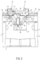
- eine schematische Vorderansicht der erfindungsgemäßen Werkzeugmaschine, bei der die Vorderwand des Querträgers und der Werkstückträger weggelassen sind;
- Fig. 3
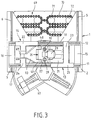
- eine schematische Draufsicht der in Fig. 1 dargestellten Werkzeugmaschine;
- Fig. 4
- eine Detailansicht einer weiteren Ausführungsform eines Koppelmechanismus zwischen den Querschlitten und der Bearbeitungseinheit; und
- Fig. 5
- eine weitere Ausführungsform der erfindungsgemäßen Werkzeugmaschine.
- Fig. 1
- the basic structure of a machine tool according to the invention in a schematic perspective view;
- Fig. 2
- is a schematic front view of the machine tool according to the invention, in which the front wall of the cross member and the workpiece carrier are omitted;
- Fig. 3
- a schematic plan view of the machine tool shown in Fig. 1;
- Fig. 4
- a detailed view of another embodiment of a coupling mechanism between the cross slide and the processing unit; and
- Fig. 5
- a further embodiment of the machine tool according to the invention.
Die in den Fig. 1 bis 3 schematisch dargestellte Werkzeugmaschine enthält einen
formsteifen Maschinenständer 1 mit zwei gegenüberliegenden Seitenteilen 2 und 3,
auf denen ein Querträger 4 über zwei parallele Führungsschienen 5, 6 durch einen
nicht dargestellten Antrieb in einer ersten Bewegungsachse (X-Achse) horizontal
verfahrbar angeordnet ist. Die als Seitenwände ausgeführten Seitenteile 2 und 3 des
Maschinenständers 1 sind durch eine hintere Querwand 7 fest miteinander verbunden,
die bei der gezeigten Ausführung derart ausgebildet ist, daß der Maschinenständer
1 an seiner Vorderseite eine in Draufsicht etwa halbkreisförmige Einbuchtung
8 zwischen den Seitenteilen 2 und 3 aufweist. Innerhalb dieser Einbuchtung 8
ist die in Draufsicht kreisrunde hintere Hälfte einer Basis 9 angeordnet. Von der
halbrunden Stirnseite der Querwand 7 wird der über der Basis 9 befindliche Arbeitsbereich
der Fräs- und Bohrmaschine nach hinten begrenzt. Auf der mit dem
Maschinenständer 1 fest verbundenen oder einteilig mit diesem ausgeführten Basis
9 ist ein im weiteren näher erläuterter Werkstückträger 10 für die Aufnahme der zu
bearbeitenden Werkstücke angeordnet. Die Oberseite der Basis 9 ist als Auffangwanne
für die bei der Bearbeitung anfallenden Späne und dgl. ausgebildet.The machine tool shown schematically in FIGS. 1 to 3 contains one
dimensionally
Auf der Oberseite des Querträgers 4 sind zwei zu den Führungsschienen 5 und 6
rechtwinklige horizontale Führungsschienen 11 und 12 montiert, auf denen zwei
Querschlitten 13 und 14 in einer zur ersten Bewegungsachse (X-Achse) rechtwinkligen
zweiten Bewegungsachse (Y-Achse) horizontal verfahrbar angeordnet sind.On the top of the
Wie besonders aus Fig. 1 und 3 hervorgeht, ist der Querträger 4 eine formsteife
rechteckige Rahmenkonstruktion, bestehend aus zwei kürzeren auf den Führungsschienen
5 und 6 laufenden Seitenteilen 15, 16 und aus einem längeren vorderen
und hinteren Querholm 17, 18, die mit Durchbrüchen versehen sind. Auf den beiden
parallelen voneinander beabstandeten Querholmen 17 und 18 sind die Führungsschienen
11 und 12 für die Querschlitten 13 und 14 befestigt. Gemäß Fig. 3 bestehen
die Querschlitten 13 und 14 jeweils aus einem über zwei Führungselemente 19
und 20 auf einer der Führungsschienen 11 bzw. 12 geführten und in deren Längsrichtung
verlaufenden Führungskörper 21 bzw. 22 und aus einem um 90° dazu abgewinkelten,
horizontalen Stützkörper 23 bzw. 24, der endseitig über ein einzelnes
Führungselement 25 auf der jeweils anderen Führungsschiene 12 bzw. 11 geführt
ist. Die beiden Querschlitten 13 und 14 sind so versetzt angeordnet, daß auf einer
Führungsschiene jeweils der Führungskörper eines Querschlittens und der Stützkörper
des anderen Querschlittens geführt sind. In den Seitenwänden der in Kastenbauweise
z.B. als Schweißkonstruktion ausgeführten Querschlitten 13 und 14 sind
Durchbrüche vorgesehen, wodurch die zu bewegende Masse verringert wird. An
den beiden Stützkörpern 23 und 24 ist eine im Freiraum zwischen den beiden beabstandeten
Querholmen 17 und 18 angeordnete Bearbeitungseinheit 26 mit hier zwei
in einem Gehäuse 27 gelagerten und durch zumindest einen Antriebsmotor 28 angetriebenen
Arbeitsspindeln 29 und 30 über Schwenkarme 31, 32 und 33 derart angelenkt,
daß die Bearbeitungseinheit 26 durch gegensinnige Verschiebung der Querschlitten
13 und 14 in der Y-Z-Ebene bewegbar ist. Durch gleichsinnige Bewegungen
beider Querschlitten 13, 14 wird die Bearbeitungseinheit 26 in der Y-Achse verfahren.As can be seen particularly from FIGS. 1 and 3, the
Wie aus Fig. 2 ersichtlich, sind die oberen Enden der beiden unteren Schwenkarme
31 und 32 über Gelenke 34 und 35 an nach unten vorstehenden Teilen 36 und 37 der
beiden Stützkörper 23 bzw. 24 angelenkt. Die unteren Enden der Schwenkarme 31
und 32 sind über Gelenke 38 und 39 an zwei seitlichen Ansätzen 40 und 41 des Gehäuses
27 der Bearbeitungseinheit 26 angelenkt. Über dem in Fig. 2 linken unteren
Schwenkarm 32 ist ein oberer Schwenkarm 33 angeordnet, der mit seinem oberen
Ende über ein Gelenk 42 an einem seitlichen Ansatz 43 des Stützkörpers 24 und mit
seinem unteren Ende am oberen Ende des Gehäuses 27 der Bearbeitungseinheit 26
angelenkt ist. Bei der in Fig. 2 dargestellten Ausführung ist der obere Schwenkarm
33 als Teleskoparm mit zwei relativ zueinander verschiebbaren inneren und äußeren
Armteilen 44 und 45 ausgeführt. Durch Aus- bzw. Einfahren des äußeren Armteils
45 über einen - nicht dargestellten - geeigneten Linearantrieb o.ä. kann so die Bearbeitungseinheit
26 gekippt und wieder in ihre gezeigte Vertikalstellung bewegt werden.As can be seen from Fig. 2, the upper ends of the two
Der obere Schwenkarm 33 kann aber auch ein starrer Träger mit unveränderlicher
Länge sein, wie dies in Fig. 1 und besonders in Fig. 3 gezeigt ist. Bei der dort dargestellten
Ausführung ist der z.B. dreiecksförmig ausgebildete obere Schwenkarm
33 mit seinem schmalen oberen Ende 46 in einer mittigen Aussparung 47 in dem
Stützkörper 24 und über zwei seitliche untere Schenkel 48 bzw. 49 an der in Fig. 3
linken Seite des Gehäuses 27 angelenkt. Bei dieser Ausführung ist jedoch keine
Schrägstellung der Bearbeitungseinheit 26 möglich. The
Bei dem als weitere Ausführung in Fig. 4 dargestellten Koppelmechanismus wird
eine Schrägstellung der Bearbeitungseinheit 26 dadurch ermöglicht, daß der in dieser
Figur linke Querschlitten 14 ein auf dem Querträger 4 über die Führungsschienen
11 und 12 horizontal verschiebbares unteres Schlittenteil 50 und ein auf diesem
über Führungsschienen 52 durch einen nicht dargestellten Antrieb motorisch verschiebbar
geführtes oberes Schlittenteil 51 aufweist. An dem unteren Schlittenteil
50 ist das obere Ende des Schwenkarms 32 und an dem oberen Schlittenteil 51 das
untere Ende des Schwenkarms 33 angelenkt. Durch Verschiebung des oberen
Schlittenteils 52 auf dem unteren Schlittenteil 51 kann so eine Schrägstellung der
Bearbeitungseinheit 26 erreicht werden.In the coupling mechanism shown as a further embodiment in FIG. 4
an inclination of the
Bei der dargestellten Werkzeugmaschine erfolgt der Antrieb der beiden Querschlitten
13 und 14 über jeweils einen in Fig. 1 und 2 dargestellten Kugelspindeltrieb, der
eine in dem Führungskörper 21 und 22 des jeweiligen Querschlittens 13 bzw. 14
angeordnete Spindelmutter 53 und eine über einen Riementrieb 54 von einem Motor
55 bzw. 56 angetriebene Gewindespindel 57 bzw. 58 enthält. Die Gewindespindeln
57 und 58 sind endseitig über Winkelstützen 59 und 60 auf dem Querträger 4 gelagert,
wobei der rechte Querschlitten 13 über die vordere Gewindespindel 57 und der
linke Querschlitten 14 über die hintere Gewindespindel 58 angetrieben werden. Die
beiden Querschlitten 13 und 14 können aber auch über Linearantriebe oder andere
geeignete Antriebe verschoben werden. In der Fig. 3 sind die Antriebe der Querschlitten
13 und 14 zur Vereinfachung weggelassen.In the machine tool shown, the two cross slides are driven
13 and 14 each have a ball screw drive shown in FIGS. 1 and 2, the
one in the
Der in den Fig. 1 und 3 dargestellte Werkstückträger 10 enthält eine vertikale Tragsäule
61, die durch einen nicht dargestellten Antrieb um ihre vertikale Mittelachse
verdrehbar etwa im Zentrum der Basis 9 angeordnet ist. An der Tragsäule 61 sind
drei in Umfangsrichtung gleichbeabstandete Winkelstützen 62 angeordnet, in deren
vertikal nach oben ragenden Endteilen 63 ein endseitiger Lagerzapfen 64 eines quaderförmigen
Spannklotzes 65, einer Spannplatte oder dgl. abgestützt ist. Über am
anderen Ende der Spannklötze 65 angeordnete Flansche 66 sind die Spannklötze 65
durch einen nicht gezeigten Antrieb um deren horizontale Mittelachse verdrehbar an
der Tragsäule 61 angeordnet. An den vier Seitenflächen jedes Spannklotzes 65 können
die zu bearbeitenden Werkstücke gespannt werden. Der gemäß Fig. 1 nach hinten
ragende Spannklotz 65 befindet sich in einer Bearbeitungsposition, während die
beiden schräg nach vorne ragenden Spannklötze in einer Rüstposition sind, so daß
dort die neu zu bearbeitenden Werkstücke aufgespannt bzw. bereits fertig bearbeitete
Werkstücke abgenommen werden können. Für den besseren Zugang zu den beiden
vorderen Spannklötzen 65 weist die Basis 9 eine in Draufsicht kreissegmentförmige
Ausnehmung 67 an seiner Vorderseite auf. Außerdem wird die in den Fig. 1
bis 3 dargestellte Werkzeugmaschine zum Schutz der Umgebung von einer nicht
gezeigten Schutzkabine umgeben.The
Durch Verfahren des Querträgers 4 kann die Bearbeitungseinheit 26 mit den beiden
parallelen Arbeitsspindeln 29 und 30 gemäß Fig. 1 in der X-Achse bewegt werden.
Bei gleichgerichteter synchroner Verschiebung der beiden Querschlitten 13 und 14
wird die Bearbeitungseinheit in der horizontalen Y-Achse und beim Zusammen-
oder Auseinanderfahren der Querschlitten 13 und 14 in der vertikalen Z-Achse verstellt.
Eine Schrägstellung der Bearbeitungseinheit 26 kann dagegen entweder durch
Ausfahren des als Teleskoparm ausgebildeten Schwenkarms 33 oder durch Verschiebung
des Schlittenoberteils 51 auf dem Schlittenunterteil 50 erreicht werden.By moving the
Der Maschinenständer 1 weist im oberen Bereich der Querwand 7 einen rechteckigen
Ausschnitt 68 auf, durch den die Bearbeitungseinheit 26 zu einer dahinterliegenden
Werkzeugspeichereinrichtung 69 verfahren werden kann. Wie aus Fig. 3
hervorgeht, besteht die Werkzeugspeichereinrichtung 69 aus vier hinter der Querwand
6 zwischen den beiden Seitenwänden 2 und 3 angeordneten Werkzeugmagazinen
70, wobei jeweils zwei der Werkzeugmagazine einander gegenüberliegend
derart angeordnet sind, daß durch minimale seitliche Bewegungen der in einer Zwischenstellung
zwischen den Werkzeugmagazinen 70 befindlichen Bearbeitungseinheit
26 gebrauchte Werkzeuge in die auf einer Seite angeordneten Werkzeugmagazine
abgelegt und neue Werkzeuge aus den gegenüberliegenden Werkzeugmagazinen
entnommen werden können. Bei der gezeigten Ausführung sind die Werkzeugmagazine
als Kettenmagazine ausgeführt, die über zwei Antriebsräder oder -scheiben
71, 72 geführt sind. Es sind aber auch Scheibenmagazine oder dgl. möglich.The machine stand 1 has a rectangular shape in the upper region of the
In Fig. 5 ist ein weiteres Ausführungsbeispiel einer erfindungsgemäßen Werkzeugmaschine
dargestellt. Bei dieser Ausführung ist der Querträger 4 über vertikale Führungsschienen
73 und 74 an einer vertikalen Front- oder Seitenwand 75 eines Maschinenständers
in einer Vertikalachse verfahrbar angeordnet. Zwischen den beiden
Querwänden 17 und 18 des Querträgers 4 ist die Bearbeitungseinheit 26 mit zwei
horizontalen Arbeitsspindeln 76 und 77 über den Koppelmechanismus mit drei
Schwenkarmen 31 bis 33 an den beiden Querschlitten 13 und 14 angelenkt. Wie bei
der vorstehend beschriebenen Ausführung sind auch dort die beiden Querschlitten
13 und 14 über geeeignete Antriebe verschiebbar am Querträger 4 angeordnet.
Durch entgegegengesetzte synchrone Verschiebung der beiden Querschlitten 13 und
14 kann über den Koppelmechanismus so eine Axialbewegung der beiden Arbeitsspindeln
76 und 77 in Horizontalrichtung realisiert werden. Bei gleichgerichteter
synchroner Verschiebung der beiden Querschlitten 13 und 14 können die beiden
Arbeitsspindeln 76 und 77 dagegen quer zu ihrer Achsrichtung horizontal bewegt
werden.5 shows a further exemplary embodiment of a machine tool according to the invention
shown. In this embodiment, the
Die Erfindung ist nicht auf die im einzelnen beschriebenen und in der Zeichnung dargestellten Ausführungsbeispiele beschränkt. So können mehrere Arbeitsspindeln auch in einer Art Rahmen, Schlitten oder dgl. angeordnet sein, so daß deren Zwischenabstand veränderlich bzw. einstellbar ist. Dadurch könnte der Bearbeitungsabstand reguliert und die Einsatzmöglichkeit vergrößert werden. Ferner kann die Bearbeitungseinheit auch um eine Vertikalachse drehbar ausgebildet sein, so daß die Stellung der einzelnen Arbeitsspindeln verändert werden kann. Anstelle der durch einen gemeinsamen Motor angetriebenen Arbeitsspindeln kann auch eine oder mehrere einzeln angetriebene Motorspindeln verwendet werden. Für die Praxis von besonderem Vorteil ist eine Variante, bei der eine oder alle Arbeitsspindeln einer Mehrspindel-Bearbeitungseinheit mit einem Längenausgleich für das jeweilige Werkzeug versehen ist, um geringfügige Längendifferenzen der einzelnen Werkzeuge, verursacht z.B. durch Verschleiß, Nachschleifen oder dgl., auf einfache Weise ohne Zeitverlust ausgleichen zu können. Dieser Längenausgleich kann manuell oder zweckmäßiger auch motorisch betätigt werden und ein Stellelement enthalten, das nach einer entsprechenden Ansteuerung eine Lagekorrektur der zugehörigen Arbeitsspindel mit dem eingespannten Werkzeug erlaubt.The invention is not based on those described in detail and in the drawing illustrated embodiments limited. So several work spindles can also be arranged in a kind of frame, slide or the like, so that their spacing is changeable or adjustable. This could reduce the machining distance regulated and the potential for use increased. Furthermore, the Machining unit can also be designed to be rotatable about a vertical axis, so that the Position of the individual work spindles can be changed. Instead of through A common motor driven work spindle can also have one or more individually driven motor spindles can be used. Special for practice The advantage is a variant in which one or all work spindles have one Multi-spindle machining unit with length compensation for the respective Tool is provided to compensate for slight differences in length of the individual tools, causes e.g. by wear, regrinding or the like, in a simple manner without being able to compensate for lost time. This length compensation can be done manually or expediently also operated by a motor and contain an actuating element, the position correction of the associated after a corresponding control Working spindle allowed with the clamped tool.
Die im einzelnen erläuterte Aufspanneinrichtung mit den mehreren Wendespannern kann außerdem durch einen starren oder auch z.B. motorisch angetriebenen Rundtisch oder dgl. ersetzt werden. The clamping device explained in detail with the several reversing clamps can also be replaced by a rigid or e.g. motorized rotary table or the like. To be replaced.
Schließlich kann bei einer Variante der in Fig. 5 dargestellten Ausführung der
Querträger 4 horizontal an einer oberen und einer unteren horizontalen stirnseitigen
Führungsschiene 73, 74 verfahrbar sein, wobei die weiteren Bauteile wie in Fig. 5
gezeigt ausgebildet sind - entsprechend einer 90°-Verdrehung dieser Fig. 5.Finally, in a variant of the embodiment shown in
Claims (16)
Applications Claiming Priority (2)
| Application Number | Priority Date | Filing Date | Title |
|---|---|---|---|
| DE10045176A DE10045176B4 (en) | 2000-09-13 | 2000-09-13 | machine tool |
| DE10045176 | 2000-09-13 |
Publications (3)
| Publication Number | Publication Date |
|---|---|
| EP1188511A2 true EP1188511A2 (en) | 2002-03-20 |
| EP1188511A3 EP1188511A3 (en) | 2003-02-12 |
| EP1188511B1 EP1188511B1 (en) | 2004-11-24 |
Family
ID=7655988
Family Applications (1)
| Application Number | Title | Priority Date | Filing Date |
|---|---|---|---|
| EP01120685A Expired - Lifetime EP1188511B1 (en) | 2000-09-13 | 2001-09-03 | Machine tool with a motor driven tool slide |
Country Status (5)
| Country | Link |
|---|---|
| US (1) | US6428453B1 (en) |
| EP (1) | EP1188511B1 (en) |
| JP (1) | JP4763938B2 (en) |
| DE (2) | DE10045176B4 (en) |
| ES (1) | ES2233537T3 (en) |
Cited By (13)
| Publication number | Priority date | Publication date | Assignee | Title |
|---|---|---|---|---|
| EP1273386A1 (en) * | 2001-06-19 | 2003-01-08 | TBT Tiefbohrtechnik GmbH | Device for positioning a spindle |
| EP1329281A2 (en) * | 2002-01-21 | 2003-07-23 | GROB-Werke Burkhart Grob e.K. | Machine tool with rod linkage mechanism |
| EP1741513A1 (en) * | 2005-07-08 | 2007-01-10 | Keppler, Karl | Machine tool with a plurality of tool spindles for circular milling of holes |
| US20090123246A1 (en) * | 2006-06-19 | 2009-05-14 | Jtekt Corporation | Machine tool with turnable movable section |
| EP2295199A1 (en) * | 2009-09-10 | 2011-03-16 | Maschinenfabrik Berthold Hermle Aktiengesellschaft | Processing centre with a tool storage within the processing centre and a tool storage shelf outside the processing centre |
| EP2656965A1 (en) * | 2012-04-27 | 2013-10-30 | Homag Holzbearbeitungssysteme GmbH | Machining device with tool change system, in particular derailleur |
| EP2957382A1 (en) * | 2014-06-17 | 2015-12-23 | Homag Holzbearbeitungssysteme GmbH | Machining centre for machining workpieces |
| CN105269410A (en) * | 2015-12-04 | 2016-01-27 | 苏州富强科技有限公司 | Intelligent machining tool |
| DE102015211496A1 (en) | 2015-06-22 | 2016-12-22 | Deckel Maho Pfronten Gmbh | Machine tool for machining a workpiece |
| CN111975042A (en) * | 2020-07-18 | 2020-11-24 | 崔通来 | Quick positioning and punching device for center hole of stainless steel pipe |
| CN114367686A (en) * | 2022-01-10 | 2022-04-19 | 江苏吉鼎金属制品有限公司 | A drilling equipment for plastic-aluminum plate processing |
| CN114786868A (en) * | 2019-09-16 | 2022-07-22 | 托尔诺斯有限公司 | Set for a machine tool, tool positioning device, rotary tool drive device and machine tool |
| EP4316731A1 (en) * | 2022-08-03 | 2024-02-07 | Sugino Machine Limited | Indexing processing machine |
Families Citing this family (39)
| Publication number | Priority date | Publication date | Assignee | Title |
|---|---|---|---|---|
| FR2781172B1 (en) * | 1998-07-20 | 2000-10-06 | Renault Automation | MACHINE TOOL, PARTICULARLY MILLING WITH CLOSED STRUCTURE AND ERGONOMIC ARRANGEMENT OF THE FUNCTIONAL PARTS OF SUCH A MACHINE TOOL |
| TWI222908B (en) * | 2001-08-30 | 2004-11-01 | Toshiba Machine Co Ltd | Vertical lathe, tool head for vertical lathe, rotary table apparatus for machine tool |
| TW521677U (en) * | 2001-10-18 | 2003-02-21 | Ind Tech Res Inst | Gantry type hybrid parallel linkage 5-axis machine tool |
| US7897642B1 (en) * | 2002-06-19 | 2011-03-01 | Dr. Irvine Dubow | Compositions and methods for dry eye syndrome |
| US8420699B1 (en) | 2002-06-19 | 2013-04-16 | Irvine L. Dubow | Composition and methods of treatment using deionized and ozonated solution |
| DE10232290B4 (en) * | 2002-07-16 | 2007-05-10 | Emag Holding Gmbh | Machining center and machining process |
| US6808344B2 (en) * | 2002-12-27 | 2004-10-26 | Jeng-Shyong Chen | Multi-axis cartesian guided parallel kinematic machine |
| US7273333B2 (en) * | 2003-06-25 | 2007-09-25 | The Boeing Company | Methods and apparatus for counterbalance-assisted manufacturing operations |
| US7488144B2 (en) | 2003-06-25 | 2009-02-10 | The Boeing Company | Methods and apparatus for track members having a neutral-axis rack |
| US7137760B2 (en) * | 2003-06-25 | 2006-11-21 | The Boeing Company | Methods and apparatus for manufacturing operations using opposing-force support systems |
| US7264426B2 (en) * | 2003-06-25 | 2007-09-04 | The Boeing Company | Apparatus and methods for servo-controlled manufacturing operations |
| US6926094B2 (en) * | 2003-06-25 | 2005-08-09 | The Boeing Company | Apparatus for manufacturing operations using non-contact position sensing |
| CN1328006C (en) * | 2003-12-31 | 2007-07-25 | 西安理工大学 | Double gantry horizontal series parallel schematic milling composite digital controlled machine tool |
| DE102004012841B3 (en) * | 2004-03-16 | 2005-09-01 | Vollmer Werke Maschinenfabrik Gmbh | Device for processing workpieces having cutting teeth such as ribbon saws blades or circular saw blades comprises a frame which pivots about a pivoting axis relative to a base |
| TWM269987U (en) * | 2005-01-07 | 2005-07-11 | Suen Cin Entpr Co Ltd | C-shaped machining center for symmetric workpiece |
| US8210782B2 (en) * | 2005-03-18 | 2012-07-03 | Horkos Corp. | Machine tool |
| WO2006100898A1 (en) | 2005-03-18 | 2006-09-28 | Horkos Corp | Machine tool |
| JP2006281390A (en) * | 2005-04-01 | 2006-10-19 | Jtekt Corp | Combined machine tool, and method for machining workpiece using the same |
| EP1754568A1 (en) * | 2005-08-19 | 2007-02-21 | Mikron Agie Charmilles AG | Machine tool with an automatic cover in the roof |
| US7551974B2 (en) * | 2006-09-15 | 2009-06-23 | Jtekt Corporation | Processing method of workpieces using combined processing machines |
| CA2663869C (en) * | 2006-09-21 | 2014-09-16 | Airbus France | Device for the overhead machining of fixed parts |
| US8066548B1 (en) | 2006-10-19 | 2011-11-29 | Max-Tek, LLC | Multi-axes contouring machine and method of use |
| JP5149031B2 (en) * | 2008-02-15 | 2013-02-20 | オークマ株式会社 | Machine Tools |
| CN101474756B (en) * | 2009-01-20 | 2011-11-16 | 西安理工大学 | Dual-drive skid revolving joint portion dual-shaft parallel high-speed accurate mainshaft head |
| IT1394985B1 (en) * | 2009-07-27 | 2012-08-07 | Salvagnini Italia Spa | LOW INERTIA MANIPULATOR FOR METAL SHEET LASER CUTTING MACHINE. |
| JP2011148010A (en) * | 2010-01-19 | 2011-08-04 | Yaskawa Electric Corp | Robot system with positioner |
| CN102069229B (en) * | 2010-12-31 | 2012-10-10 | 南车石家庄车辆有限公司 | Fixture special for milling bottom surface of side bearing seat for rail wagon |
| CN102218596A (en) * | 2011-06-24 | 2011-10-19 | 江苏大学 | Serial-parallel laser process machine |
| EP2698218A1 (en) | 2012-08-17 | 2014-02-19 | Bühler GmbH | Tool, stencil, cartridge and method for corrugating a roller |
| CN103273356B (en) * | 2013-04-28 | 2015-09-30 | 清华大学 | A kind of multi-axes synchronous hybrid device based on four-freedom parallel mechanism |
| JP5836464B1 (en) * | 2014-10-09 | 2015-12-24 | 株式会社アマダマシンツール | Machine Tools |
| CN105500007B (en) * | 2015-12-30 | 2017-11-24 | 浙江万丰科技开发股份有限公司 | A kind of rotary Motorcycle Aluminum Alloy wheel hub drilling all-in-one |
| CN106272354A (en) * | 2016-09-13 | 2017-01-04 | 浙江理工大学 | A kind of plane two one-movement-freedom-degree compliant parallel mechanism of large stroke and high precision |
| CN107900756A (en) * | 2017-12-29 | 2018-04-13 | 天津天海精密锻造有限公司 | A kind of high-pressure common rail axle clamp tool and its application method |
| CA3028686A1 (en) * | 2018-12-14 | 2020-06-14 | Travis Everett Vap | A machine and method of manufacture for eifs panels |
| CN109551016A (en) * | 2019-01-18 | 2019-04-02 | 南通瑞格精密机械有限公司 | It is a kind of for processing the numerical control gantry Finish Milling Machine of straight-bar machines pedestal |
| JP7316873B2 (en) * | 2019-08-08 | 2023-07-28 | オークマ株式会社 | Multi-spindle machine tool |
| JP2021122932A (en) * | 2020-02-10 | 2021-08-30 | Towa株式会社 | Processing device |
| CN111590091B (en) | 2020-05-19 | 2022-12-20 | 科德数控股份有限公司 | Double-swing-angle spindle head |
Citations (4)
| Publication number | Priority date | Publication date | Assignee | Title |
|---|---|---|---|---|
| DE29705152U1 (en) * | 1997-03-21 | 1997-07-10 | Elektronik Entwicklung Gmbh | Machining center |
| WO1999008832A1 (en) * | 1997-08-20 | 1999-02-25 | Mikron Sa Agno | Device for moving and positioning an object in a plane |
| DE29914888U1 (en) * | 1999-04-15 | 1999-12-23 | Bonneick Sonja | Device for machining workpieces |
| DE19924823A1 (en) * | 1999-05-29 | 2000-11-30 | Manfred Weck | Device for finishing and assembling workpieces has support connectable to coupling members of which one is body of variable length which changes as support is adjusted by actor |
Family Cites Families (20)
| Publication number | Priority date | Publication date | Assignee | Title |
|---|---|---|---|---|
| JPS59142035A (en) * | 1983-01-31 | 1984-08-15 | Kitamura Kikai Kk | Indexing device for multi-surface processing |
| DE3503300A1 (en) * | 1985-01-31 | 1986-08-07 | Rudi 7080 Aalen Körner | Milling machine |
| JPS6347033A (en) * | 1986-08-08 | 1988-02-27 | Mitsubishi Heavy Ind Ltd | High-speed machining device |
| DE4027895A1 (en) * | 1990-09-03 | 1992-03-05 | Wanderer Maschinen Gmbh | Workpiece table for machine tool - can be rotated about axis which is at right angles to spindle axis |
| JPH078463B2 (en) * | 1990-10-19 | 1995-02-01 | 和也 廣瀬 | Table positioning mechanism |
| US5154643A (en) * | 1990-10-29 | 1992-10-13 | Gemcor Engineering Corporation | Method and apparatus for positioning tooling |
| JPH04250911A (en) * | 1990-12-28 | 1992-09-07 | Ishikawajima Harima Heavy Ind Co Ltd | Portal cutting machine |
| US5187822A (en) * | 1991-11-14 | 1993-02-23 | Anodyne Corporation | Portable patient crane |
| US5314397A (en) * | 1992-07-31 | 1994-05-24 | Ford Motor Company | Positioning apparatus for multiple-spindle machining |
| DE4444614A1 (en) * | 1994-12-14 | 1996-06-20 | Deckel Maho Gmbh | Machine tool |
| JP3626265B2 (en) * | 1995-12-18 | 2005-03-02 | 本田技研工業株式会社 | Machine Tools |
| JP2000502000A (en) * | 1995-12-20 | 2000-02-22 | アレクサンダー コンラート ヴィーガント | Apparatus for controlled body movement in three to six degrees of freedom |
| DE19623511A1 (en) * | 1996-06-13 | 1997-12-18 | Vdw Ev | Device for processing and / or assembling workpieces |
| SG60075A1 (en) * | 1996-06-26 | 1999-02-22 | Starrgrasmaschinen Ag | Rigid machining centre |
| JP3685879B2 (en) * | 1996-07-26 | 2005-08-24 | 東芝機械株式会社 | Machine tool with pivotable spindle head |
| US5848458A (en) * | 1997-05-15 | 1998-12-15 | Northrop Grumman Corporation | Reconfigurable gantry tool |
| DE19806085B4 (en) * | 1997-10-20 | 2004-11-11 | Cross Hüller GmbH | Machine tool for 3-axis machining of workpieces |
| JP2000210832A (en) * | 1999-01-25 | 2000-08-02 | Okuma Corp | Drive mechanism for moving body, and machine tool |
| US6357094B1 (en) * | 1999-02-26 | 2002-03-19 | Mori Seiki Co., Ltd. | Machine tool |
| US6254317B1 (en) * | 1999-09-10 | 2001-07-03 | Northrop Grumman Corporation | Triple gantry drilling system |
-
2000
- 2000-09-13 DE DE10045176A patent/DE10045176B4/en not_active Expired - Fee Related
-
2001
- 2001-09-03 ES ES01120685T patent/ES2233537T3/en not_active Expired - Lifetime
- 2001-09-03 DE DE50104586T patent/DE50104586D1/en not_active Expired - Lifetime
- 2001-09-03 EP EP01120685A patent/EP1188511B1/en not_active Expired - Lifetime
- 2001-09-07 US US09/949,485 patent/US6428453B1/en not_active Expired - Fee Related
- 2001-09-12 JP JP2001275834A patent/JP4763938B2/en not_active Expired - Fee Related
Patent Citations (4)
| Publication number | Priority date | Publication date | Assignee | Title |
|---|---|---|---|---|
| DE29705152U1 (en) * | 1997-03-21 | 1997-07-10 | Elektronik Entwicklung Gmbh | Machining center |
| WO1999008832A1 (en) * | 1997-08-20 | 1999-02-25 | Mikron Sa Agno | Device for moving and positioning an object in a plane |
| DE29914888U1 (en) * | 1999-04-15 | 1999-12-23 | Bonneick Sonja | Device for machining workpieces |
| DE19924823A1 (en) * | 1999-05-29 | 2000-11-30 | Manfred Weck | Device for finishing and assembling workpieces has support connectable to coupling members of which one is body of variable length which changes as support is adjusted by actor |
Cited By (18)
| Publication number | Priority date | Publication date | Assignee | Title |
|---|---|---|---|---|
| EP1273386A1 (en) * | 2001-06-19 | 2003-01-08 | TBT Tiefbohrtechnik GmbH | Device for positioning a spindle |
| EP1329281A2 (en) * | 2002-01-21 | 2003-07-23 | GROB-Werke Burkhart Grob e.K. | Machine tool with rod linkage mechanism |
| EP1329281A3 (en) * | 2002-01-21 | 2006-03-29 | GROB-Werke Burkhart Grob e.K. | Machine tool with rod linkage mechanism |
| EP1741513A1 (en) * | 2005-07-08 | 2007-01-10 | Keppler, Karl | Machine tool with a plurality of tool spindles for circular milling of holes |
| US20090123246A1 (en) * | 2006-06-19 | 2009-05-14 | Jtekt Corporation | Machine tool with turnable movable section |
| US8414233B2 (en) * | 2006-06-19 | 2013-04-09 | Jtekt Corporation | Machine tool with turnable moving section |
| EP2295199A1 (en) * | 2009-09-10 | 2011-03-16 | Maschinenfabrik Berthold Hermle Aktiengesellschaft | Processing centre with a tool storage within the processing centre and a tool storage shelf outside the processing centre |
| EP2656965A1 (en) * | 2012-04-27 | 2013-10-30 | Homag Holzbearbeitungssysteme GmbH | Machining device with tool change system, in particular derailleur |
| EP2957382A1 (en) * | 2014-06-17 | 2015-12-23 | Homag Holzbearbeitungssysteme GmbH | Machining centre for machining workpieces |
| DE102015211496A1 (en) | 2015-06-22 | 2016-12-22 | Deckel Maho Pfronten Gmbh | Machine tool for machining a workpiece |
| WO2016207223A2 (en) | 2015-06-22 | 2016-12-29 | Deckel Maho Pfronten Gmbh | Machine tool for machining a workpiece |
| WO2016207223A3 (en) * | 2015-06-22 | 2017-03-16 | Deckel Maho Pfronten Gmbh | Machine tool for machining a workpiece |
| US10807205B2 (en) | 2015-06-22 | 2020-10-20 | Deckel Maho Pfronten Gmbh | Machine tool for machining a workpiece |
| CN105269410A (en) * | 2015-12-04 | 2016-01-27 | 苏州富强科技有限公司 | Intelligent machining tool |
| CN114786868A (en) * | 2019-09-16 | 2022-07-22 | 托尔诺斯有限公司 | Set for a machine tool, tool positioning device, rotary tool drive device and machine tool |
| CN111975042A (en) * | 2020-07-18 | 2020-11-24 | 崔通来 | Quick positioning and punching device for center hole of stainless steel pipe |
| CN114367686A (en) * | 2022-01-10 | 2022-04-19 | 江苏吉鼎金属制品有限公司 | A drilling equipment for plastic-aluminum plate processing |
| EP4316731A1 (en) * | 2022-08-03 | 2024-02-07 | Sugino Machine Limited | Indexing processing machine |
Also Published As
| Publication number | Publication date |
|---|---|
| JP4763938B2 (en) | 2011-08-31 |
| EP1188511A3 (en) | 2003-02-12 |
| DE10045176B4 (en) | 2004-03-18 |
| EP1188511B1 (en) | 2004-11-24 |
| ES2233537T3 (en) | 2005-06-16 |
| US6428453B1 (en) | 2002-08-06 |
| JP2002144176A (en) | 2002-05-21 |
| DE50104586D1 (en) | 2004-12-30 |
| DE10045176A1 (en) | 2002-04-04 |
Similar Documents
| Publication | Publication Date | Title |
|---|---|---|
| EP1188511B1 (en) | Machine tool with a motor driven tool slide | |
| DE3240911C2 (en) | ||
| EP0868255B1 (en) | Device for spatially moving a body with three to six degrees of freedom in a controlled manner | |
| EP0721819B1 (en) | Machine tool | |
| EP1287945B1 (en) | Universal milling and boring machine | |
| EP2318177B1 (en) | Machine tool having a carrier device for work pieces or tools | |
| DE602006000545T2 (en) | Machining center with two working units with means for handling the workpiece | |
| DE3721610C2 (en) | ||
| EP0812652B1 (en) | Device for manufacturing and/or assembling workpieces | |
| DE946500C (en) | Two-column milling and boring mill | |
| EP0995539A2 (en) | Machining device for work pieces | |
| EP1409182B1 (en) | Machine tool | |
| DE19854276C2 (en) | Machine tool arrangement with a device for an automatic tool change | |
| DE19919645A1 (en) | Machine tool for drilling and cutting, has turning tool mounted in clamp separate from spindle | |
| DE202017003923U1 (en) | Machining center for metal profiles | |
| DE60009200T2 (en) | Machine tool for processing symmetrical elongated elements such as, for example, components for chairs, furniture or other such objects | |
| DE19516263A1 (en) | CNC controlled wood machining system, esp. for long timber workpieces, e.g. planks | |
| EP1058593A1 (en) | Hexapod machining centre | |
| EP1651381B1 (en) | Machine tool comprising a clamping device on both sides | |
| DE10302317A1 (en) | Machinetool bar kinematics comprise bars hinged to spindle holder and guided slide foot with joints used to position spindles in respective axes. | |
| EP0331178B1 (en) | Compact construction of a column drilling machine | |
| DE102015121925A1 (en) | machine tool | |
| EP0787560B1 (en) | Device for working bars, profiles and the like | |
| DE102006011551A1 (en) | machine tool | |
| DE19609072A1 (en) | Three=dimensional positioning of tool holding plate |
Legal Events
| Date | Code | Title | Description |
|---|---|---|---|
| PUAI | Public reference made under article 153(3) epc to a published international application that has entered the european phase |
Free format text: ORIGINAL CODE: 0009012 |
|
| AK | Designated contracting states |
Kind code of ref document: A2 Designated state(s): AT BE CH CY DE DK ES FI FR GB GR IE IT LI LU MC NL PT SE TR |
|
| AX | Request for extension of the european patent |
Free format text: AL;LT;LV;MK;RO;SI |
|
| PUAL | Search report despatched |
Free format text: ORIGINAL CODE: 0009013 |
|
| AK | Designated contracting states |
Designated state(s): AT BE CH CY DE DK ES FI FR GB GR IE IT LI LU MC NL PT SE TR |
|
| AX | Request for extension of the european patent |
Extension state: AL LT LV MK RO SI |
|
| 17P | Request for examination filed |
Effective date: 20030730 |
|
| AKX | Designation fees paid |
Designated state(s): CH DE ES FR GB IT LI |
|
| 17Q | First examination report despatched |
Effective date: 20031208 |
|
| GRAP | Despatch of communication of intention to grant a patent |
Free format text: ORIGINAL CODE: EPIDOSNIGR1 |
|
| GRAS | Grant fee paid |
Free format text: ORIGINAL CODE: EPIDOSNIGR3 |
|
| GRAA | (expected) grant |
Free format text: ORIGINAL CODE: 0009210 |
|
| AK | Designated contracting states |
Kind code of ref document: B1 Designated state(s): CH DE ES FR GB IT LI |
|
| REG | Reference to a national code |
Ref country code: GB Ref legal event code: FG4D Free format text: NOT ENGLISH |
|
| REG | Reference to a national code |
Ref country code: CH Ref legal event code: NV Representative=s name: MICHELI & CIE INGENIEURS-CONSEILS Ref country code: CH Ref legal event code: EP |
|
| REF | Corresponds to: |
Ref document number: 50104586 Country of ref document: DE Date of ref document: 20041230 Kind code of ref document: P |
|
| REG | Reference to a national code |
Ref country code: IE Ref legal event code: FG4D Free format text: GERMAN |
|
| REG | Reference to a national code |
Ref country code: ES Ref legal event code: FG2A Ref document number: 2233537 Country of ref document: ES Kind code of ref document: T3 |
|
| REG | Reference to a national code |
Ref country code: IE Ref legal event code: FD4D |
|
| ET | Fr: translation filed | ||
| PLBE | No opposition filed within time limit |
Free format text: ORIGINAL CODE: 0009261 |
|
| STAA | Information on the status of an ep patent application or granted ep patent |
Free format text: STATUS: NO OPPOSITION FILED WITHIN TIME LIMIT |
|
| 26N | No opposition filed |
Effective date: 20050825 |
|
| PGFP | Annual fee paid to national office [announced via postgrant information from national office to epo] |
Ref country code: ES Payment date: 20130816 Year of fee payment: 13 Ref country code: CH Payment date: 20130821 Year of fee payment: 13 |
|
| PGFP | Annual fee paid to national office [announced via postgrant information from national office to epo] |
Ref country code: GB Payment date: 20130927 Year of fee payment: 13 |
|
| PGFP | Annual fee paid to national office [announced via postgrant information from national office to epo] |
Ref country code: IT Payment date: 20130916 Year of fee payment: 13 |
|
| PGFP | Annual fee paid to national office [announced via postgrant information from national office to epo] |
Ref country code: FR Payment date: 20130925 Year of fee payment: 13 |
|
| PGFP | Annual fee paid to national office [announced via postgrant information from national office to epo] |
Ref country code: DE Payment date: 20140930 Year of fee payment: 14 |
|
| REG | Reference to a national code |
Ref country code: CH Ref legal event code: PL |
|
| GBPC | Gb: european patent ceased through non-payment of renewal fee |
Effective date: 20140903 |
|
| REG | Reference to a national code |
Ref country code: FR Ref legal event code: ST Effective date: 20150529 |
|
| PG25 | Lapsed in a contracting state [announced via postgrant information from national office to epo] |
Ref country code: CH Free format text: LAPSE BECAUSE OF NON-PAYMENT OF DUE FEES Effective date: 20140930 Ref country code: GB Free format text: LAPSE BECAUSE OF NON-PAYMENT OF DUE FEES Effective date: 20140903 Ref country code: LI Free format text: LAPSE BECAUSE OF NON-PAYMENT OF DUE FEES Effective date: 20140930 |
|
| PG25 | Lapsed in a contracting state [announced via postgrant information from national office to epo] |
Ref country code: IT Free format text: LAPSE BECAUSE OF NON-PAYMENT OF DUE FEES Effective date: 20140903 Ref country code: FR Free format text: LAPSE BECAUSE OF NON-PAYMENT OF DUE FEES Effective date: 20140930 |
|
| REG | Reference to a national code |
Ref country code: ES Ref legal event code: FD2A Effective date: 20151029 |
|
| PG25 | Lapsed in a contracting state [announced via postgrant information from national office to epo] |
Ref country code: ES Free format text: LAPSE BECAUSE OF NON-PAYMENT OF DUE FEES Effective date: 20140904 |
|
| REG | Reference to a national code |
Ref country code: DE Ref legal event code: R119 Ref document number: 50104586 Country of ref document: DE |
|
| PG25 | Lapsed in a contracting state [announced via postgrant information from national office to epo] |
Ref country code: DE Free format text: LAPSE BECAUSE OF NON-PAYMENT OF DUE FEES Effective date: 20160401 |