EP1187980B1 - Turbocharger incorporating an integral pump for exhaust gas recirculation - Google Patents
Turbocharger incorporating an integral pump for exhaust gas recirculation Download PDFInfo
- Publication number
- EP1187980B1 EP1187980B1 EP00941503A EP00941503A EP1187980B1 EP 1187980 B1 EP1187980 B1 EP 1187980B1 EP 00941503 A EP00941503 A EP 00941503A EP 00941503 A EP00941503 A EP 00941503A EP 1187980 B1 EP1187980 B1 EP 1187980B1
- Authority
- EP
- European Patent Office
- Prior art keywords
- exhaust gas
- housing
- turbocharger
- egr
- inlet
- Prior art date
- Legal status (The legal status is an assumption and is not a legal conclusion. Google has not performed a legal analysis and makes no representation as to the accuracy of the status listed.)
- Expired - Lifetime
Links
Images




Classifications
-
- F—MECHANICAL ENGINEERING; LIGHTING; HEATING; WEAPONS; BLASTING
- F02—COMBUSTION ENGINES; HOT-GAS OR COMBUSTION-PRODUCT ENGINE PLANTS
- F02B—INTERNAL-COMBUSTION PISTON ENGINES; COMBUSTION ENGINES IN GENERAL
- F02B37/00—Engines characterised by provision of pumps driven at least for part of the time by exhaust
-
- F—MECHANICAL ENGINEERING; LIGHTING; HEATING; WEAPONS; BLASTING
- F02—COMBUSTION ENGINES; HOT-GAS OR COMBUSTION-PRODUCT ENGINE PLANTS
- F02B—INTERNAL-COMBUSTION PISTON ENGINES; COMBUSTION ENGINES IN GENERAL
- F02B37/00—Engines characterised by provision of pumps driven at least for part of the time by exhaust
- F02B37/005—Exhaust driven pumps being combined with an exhaust driven auxiliary apparatus, e.g. a ventilator
-
- F—MECHANICAL ENGINEERING; LIGHTING; HEATING; WEAPONS; BLASTING
- F02—COMBUSTION ENGINES; HOT-GAS OR COMBUSTION-PRODUCT ENGINE PLANTS
- F02B—INTERNAL-COMBUSTION PISTON ENGINES; COMBUSTION ENGINES IN GENERAL
- F02B37/00—Engines characterised by provision of pumps driven at least for part of the time by exhaust
- F02B37/02—Gas passages between engine outlet and pump drive, e.g. reservoirs
- F02B37/025—Multiple scrolls or multiple gas passages guiding the gas to the pump drive
-
- F—MECHANICAL ENGINEERING; LIGHTING; HEATING; WEAPONS; BLASTING
- F02—COMBUSTION ENGINES; HOT-GAS OR COMBUSTION-PRODUCT ENGINE PLANTS
- F02B—INTERNAL-COMBUSTION PISTON ENGINES; COMBUSTION ENGINES IN GENERAL
- F02B37/00—Engines characterised by provision of pumps driven at least for part of the time by exhaust
- F02B37/12—Control of the pumps
- F02B37/24—Control of the pumps by using pumps or turbines with adjustable guide vanes
-
- F—MECHANICAL ENGINEERING; LIGHTING; HEATING; WEAPONS; BLASTING
- F02—COMBUSTION ENGINES; HOT-GAS OR COMBUSTION-PRODUCT ENGINE PLANTS
- F02M—SUPPLYING COMBUSTION ENGINES IN GENERAL WITH COMBUSTIBLE MIXTURES OR CONSTITUENTS THEREOF
- F02M26/00—Engine-pertinent apparatus for adding exhaust gases to combustion-air, main fuel or fuel-air mixture, e.g. by exhaust gas recirculation [EGR] systems
- F02M26/02—EGR systems specially adapted for supercharged engines
- F02M26/04—EGR systems specially adapted for supercharged engines with a single turbocharger
- F02M26/05—High pressure loops, i.e. wherein recirculated exhaust gas is taken out from the exhaust system upstream of the turbine and reintroduced into the intake system downstream of the compressor
-
- F—MECHANICAL ENGINEERING; LIGHTING; HEATING; WEAPONS; BLASTING
- F02—COMBUSTION ENGINES; HOT-GAS OR COMBUSTION-PRODUCT ENGINE PLANTS
- F02M—SUPPLYING COMBUSTION ENGINES IN GENERAL WITH COMBUSTIBLE MIXTURES OR CONSTITUENTS THEREOF
- F02M26/00—Engine-pertinent apparatus for adding exhaust gases to combustion-air, main fuel or fuel-air mixture, e.g. by exhaust gas recirculation [EGR] systems
- F02M26/02—EGR systems specially adapted for supercharged engines
- F02M26/09—Constructional details, e.g. structural combinations of EGR systems and supercharger systems; Arrangement of the EGR and supercharger systems with respect to the engine
- F02M26/10—Constructional details, e.g. structural combinations of EGR systems and supercharger systems; Arrangement of the EGR and supercharger systems with respect to the engine having means to increase the pressure difference between the exhaust and intake system, e.g. venturis, variable geometry turbines, check valves using pressure pulsations or throttles in the air intake or exhaust system
-
- F—MECHANICAL ENGINEERING; LIGHTING; HEATING; WEAPONS; BLASTING
- F02—COMBUSTION ENGINES; HOT-GAS OR COMBUSTION-PRODUCT ENGINE PLANTS
- F02M—SUPPLYING COMBUSTION ENGINES IN GENERAL WITH COMBUSTIBLE MIXTURES OR CONSTITUENTS THEREOF
- F02M26/00—Engine-pertinent apparatus for adding exhaust gases to combustion-air, main fuel or fuel-air mixture, e.g. by exhaust gas recirculation [EGR] systems
- F02M26/13—Arrangement or layout of EGR passages, e.g. in relation to specific engine parts or for incorporation of accessories
- F02M26/17—Arrangement or layout of EGR passages, e.g. in relation to specific engine parts or for incorporation of accessories in relation to the intake system
- F02M26/19—Means for improving the mixing of air and recirculated exhaust gases, e.g. venturis or multiple openings to the intake system
-
- F—MECHANICAL ENGINEERING; LIGHTING; HEATING; WEAPONS; BLASTING
- F02—COMBUSTION ENGINES; HOT-GAS OR COMBUSTION-PRODUCT ENGINE PLANTS
- F02M—SUPPLYING COMBUSTION ENGINES IN GENERAL WITH COMBUSTIBLE MIXTURES OR CONSTITUENTS THEREOF
- F02M26/00—Engine-pertinent apparatus for adding exhaust gases to combustion-air, main fuel or fuel-air mixture, e.g. by exhaust gas recirculation [EGR] systems
- F02M26/13—Arrangement or layout of EGR passages, e.g. in relation to specific engine parts or for incorporation of accessories
- F02M26/22—Arrangement or layout of EGR passages, e.g. in relation to specific engine parts or for incorporation of accessories with coolers in the recirculation passage
- F02M26/23—Layout, e.g. schematics
-
- F—MECHANICAL ENGINEERING; LIGHTING; HEATING; WEAPONS; BLASTING
- F02—COMBUSTION ENGINES; HOT-GAS OR COMBUSTION-PRODUCT ENGINE PLANTS
- F02M—SUPPLYING COMBUSTION ENGINES IN GENERAL WITH COMBUSTIBLE MIXTURES OR CONSTITUENTS THEREOF
- F02M26/00—Engine-pertinent apparatus for adding exhaust gases to combustion-air, main fuel or fuel-air mixture, e.g. by exhaust gas recirculation [EGR] systems
- F02M26/13—Arrangement or layout of EGR passages, e.g. in relation to specific engine parts or for incorporation of accessories
- F02M26/34—Arrangement or layout of EGR passages, e.g. in relation to specific engine parts or for incorporation of accessories with compressors, turbines or the like in the recirculation passage
-
- F—MECHANICAL ENGINEERING; LIGHTING; HEATING; WEAPONS; BLASTING
- F02—COMBUSTION ENGINES; HOT-GAS OR COMBUSTION-PRODUCT ENGINE PLANTS
- F02B—INTERNAL-COMBUSTION PISTON ENGINES; COMBUSTION ENGINES IN GENERAL
- F02B29/00—Engines characterised by provision for charging or scavenging not provided for in groups F02B25/00, F02B27/00 or F02B33/00 - F02B39/00; Details thereof
- F02B29/04—Cooling of air intake supply
- F02B29/0406—Layout of the intake air cooling or coolant circuit
-
- F—MECHANICAL ENGINEERING; LIGHTING; HEATING; WEAPONS; BLASTING
- F02—COMBUSTION ENGINES; HOT-GAS OR COMBUSTION-PRODUCT ENGINE PLANTS
- F02M—SUPPLYING COMBUSTION ENGINES IN GENERAL WITH COMBUSTIBLE MIXTURES OR CONSTITUENTS THEREOF
- F02M26/00—Engine-pertinent apparatus for adding exhaust gases to combustion-air, main fuel or fuel-air mixture, e.g. by exhaust gas recirculation [EGR] systems
- F02M26/02—EGR systems specially adapted for supercharged engines
- F02M26/08—EGR systems specially adapted for supercharged engines for engines having two or more intake charge compressors or exhaust gas turbines, e.g. a turbocharger combined with an additional compressor
-
- F—MECHANICAL ENGINEERING; LIGHTING; HEATING; WEAPONS; BLASTING
- F02—COMBUSTION ENGINES; HOT-GAS OR COMBUSTION-PRODUCT ENGINE PLANTS
- F02M—SUPPLYING COMBUSTION ENGINES IN GENERAL WITH COMBUSTIBLE MIXTURES OR CONSTITUENTS THEREOF
- F02M26/00—Engine-pertinent apparatus for adding exhaust gases to combustion-air, main fuel or fuel-air mixture, e.g. by exhaust gas recirculation [EGR] systems
- F02M26/13—Arrangement or layout of EGR passages, e.g. in relation to specific engine parts or for incorporation of accessories
- F02M26/14—Arrangement or layout of EGR passages, e.g. in relation to specific engine parts or for incorporation of accessories in relation to the exhaust system
- F02M26/16—Arrangement or layout of EGR passages, e.g. in relation to specific engine parts or for incorporation of accessories in relation to the exhaust system with EGR valves located at or near the connection to the exhaust system
-
- Y—GENERAL TAGGING OF NEW TECHNOLOGICAL DEVELOPMENTS; GENERAL TAGGING OF CROSS-SECTIONAL TECHNOLOGIES SPANNING OVER SEVERAL SECTIONS OF THE IPC; TECHNICAL SUBJECTS COVERED BY FORMER USPC CROSS-REFERENCE ART COLLECTIONS [XRACs] AND DIGESTS
- Y02—TECHNOLOGIES OR APPLICATIONS FOR MITIGATION OR ADAPTATION AGAINST CLIMATE CHANGE
- Y02T—CLIMATE CHANGE MITIGATION TECHNOLOGIES RELATED TO TRANSPORTATION
- Y02T10/00—Road transport of goods or passengers
- Y02T10/10—Internal combustion engine [ICE] based vehicles
- Y02T10/12—Improving ICE efficiencies
Definitions
- the present invention is related generally to the field of internal combustion engine exhaust gas recirculation (EGR) for emissions improvement. More particularly, the invention provides a turbocharger compressor wheel having impeller vanes mounted on a side opposite the compressor impeller to act as an EGR pump with a separate diffuser and volute for EGR flow output from the pump and a separate scroll inlet to the EGR pump for recirculating exhaust gas in the charge air for the engine.
- EGR exhaust gas recirculation
- EGR is a known method for reducing the NOX emissions in internal combustion engines.
- an EGR system must overcome the adverse pressure gradient created by a positive pressure gradient across the engine which is typical of modern high efficiency diesel engines in at least a portion of their operating range.
- Various approaches to implementing EGR have included pumping of a portion of the exhaust gas from the exhaust manifold to the intake manifold.
- control of back pressure in the exhaust system may be required to achieve desired system performance by enhancing the pumping capability and, if EGR is modulated or turned off, air fuel ratio control for the engine is desirable to maintain optimum engine performance.
- EGR system The components and features of an EGR system must be accommodated within the constraints of limited volume available for allocation in modern engine compartments. It is, therefore, desirable to provide a highly integrated EGR system employing pumping components for recirculation of exhaust gas in close physical and functional cooperation with existing engine system components such as a turbocharger and providing exhaust back pressure and air fuel ratio control within the integrated system.
- turbocharger incorporating a integral Exhaust Gas Recirculation (EGR) pump, the turbocharger comprising:
- FIG. 1 shows an internal combustion engine 10 having an intake manifold 12 and an exhaust manifold 14.
- a turbocharger 16 is provided for charge air boost, receiving intake air for compression by a compressor rotor 18 which provides the pressurized air to a charge air cooler 20 prior to introduction into the intake manifold.
- the compressor rotor is driven by a shaft 22 connected to a turbine 24 receiving exhaust gas from the exhaust manifold of the engine.
- Exhaust gas for recirculation is diverted from the flow out of the exhaust manifold through a control valve 26 to an EGR cooler 28.
- Gas from the EGR cooler is provided to the inlet of an EGR pump which, for the embodiment shown in the drawings, is a compressor rotor 30 mounted to the turbocharger shaft to be driven by the turbine.
- the pressurized exhaust gas from the EGR pump flows to a mixer 32 which combines the recirculated exhaust flow with the charge air to create a substantially homogenous flow stream for introduction into the intake manifold.
- variable geometry inlet 33 for the turbocharger turbine provides control of engine exhaust back pressure. Further, the variable geometry inlet allows enhanced air fuel ratio control through modulation of compressor boost pressure by varying turbine inlet area to control turbine power.
- FIG. 2 shows the details of a turbocharger employing an integral EGR compressor according to the present invention.
- the turbine is contained in a cast turbine housing 34 which incorporates a radial exhaust gas inlet 36 feeding a bifurcated volute 38, for the embodiment shown in the drawings. Gas flowing through the turbine exits at turbine outlet 40.
- Shaft 22 is supported by a bearing system including journal bearings 42 separated by spacer 44 and thrust collar 46 with bearing 48 all carried within a center housing 50 which incorporates lubrication channels 52.
- the bearing 48 is attached to the center housing with bolt 49.
- the charge air compressor is contained within a cast compressor housing 54 which provides an air inlet 56, a diffuser 58 and a volute 60 for the compressed charge air.
- a toroidal inlet is employed while in alternative embodiments, a scroll inlet is used.
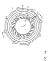
- the EGR pump is incorporated into the existing rotor group of the turbocharger by adding impeller vanes 62 to the back side of the compressor wheel.
- a scroll inlet 64 provides exhaust gas for recirculation and a separate diffuser 66 carries the pressurized exhaust gas to a volute 68.
- the EGR pump inlet, diffuser and volute are incorporated in a casting 70 which replaces the conventional compressor back plate for the turbocharger, thereby requiring only a small increase in the length of the rotor group and turbocharger as a whole.
- Segregation of the charge air flow in the compressor and the recirculated exhaust gas in the EGR pump is maintained by a baffle 72 which is constrained between the compressor housing and EGR pump casting.
- the EGR pump casting is mounted to the compressor housing using a retaining ring 74 and bolts 76 received in the compressor housing.
- the baffle engages the rotor in two step seals, a first seal 80 at the circumference of the rotor and a second seal 82 on the EGR pump side of the rotor, inset from the circumference adjacent the leading edge of the pump impeller vanes.
- a scroll seal 84 is also employed in the embodiment shown in the drawings, to create a pressure differential further enhancing the separation of the EGR flow and charge air flow in the turbocharger to avoid fouling of the charge air flow components such as the charge air cooler downstream of the turbocharger.
- a cover 86 is attached to the EGR pump casting with machine screws 88.
- the cover extends, in the embodiment shown, from the EGR inlet to the EGR volute and provides a second surface for cooperation with the inner surface of the baffle to form the EGR pump impeller diffuser.
- the cover further overlays the attachment bolts 89, which secure the pump casting to the center housing 50, for improved aerodynamics.
- the cover is machined on surface 90 to provide the proper trim for the EGR pump impeller blades allowing flexibility for common use of the EGR pump casting with various engine EGR pumping requirements.
- resilient seals 92 and 94 provide additional sealing of the compressor housing to the baffle/EGR pump casting and the EGR pump casting to the center housing, respectively.
- Piston seals 96 provide sealing of the rotating shaft adjacent the compressor and turbine.
- the turbine housing is attached to the center housing using a V-band 98 and a heat shield 99 is supported between the center housing and turbine housing.
- FIGs. 4a and 4b show a center housing and turbine housing arrangement employing a variable geometry turbine inlet for use in the present invention.
- a multiple rotating vane configuration comparable to that disclosed in US patent application serial no. 09/033274 filed March 2, 1998 entitled Pressure Balanced Dual Axle Variable Nozzle Turbocharger and having a common assignee with the present application, is provided for the embodiment shown in the drawings.
- the vanes 100 of the variable geometry nozzle 33 are supported by axles extending into nozzle ring 102 which, in the embodiment shown, is supported in spaced relation to the turbine housing 34 by a plurality of spacer pins 104 and fixed by a disk spring 106 secured by a retaining ring 107.
- a unison ring 108 rotatably mounted on rollers 110 supported by dowel pins 112, provides the actuation for the multiple vanes.
- Rotation of the unison ring rotates the vanes through a range of motion from a first substantially open position providing maximum nozzle entrance area and flow to a second substantially closed position providing minimum nozzle entrance area.
- Each of the vanes is partially supported by a first axle 114 which extends in close relation into and is rotatably supported by apertures 116 in the nozzle ring.
- the first axle extends through the nozzle ring and is attached to a vane arm 118 which is received in slots in the unison ring for actuation of the vanes.
- Rotation of the unison ring is accomplished by an external crank 120 and an actuator linkage including rod 121 and crank arm 123.
- a second axle 122 extends from each of the vanes, opposite and co-axial with the first axle.
- the second axle extends in close relation into and is rotatably supported by mating apertures 124 in an insert ring 126 which is recessed into the turbine housing and carried by a machined relief 128.
- the nozzle ring and insert ring form the bounding hub and shroud surfaces of the nozzle.
- Three precision hollow, circular spacers 130, surrounding the spacer pins 104, are used to precisely locate and space the two rings and to secure the nozzle ring assembly to the turbine housing between the nozzle inlet and the nozzle outlet adjacent the turbine.
- Exhaust gas from the engine is received by the turbocharger through radial inlet 36 into the volute 38.
- a bypass 134 is provided from the volute.
- An EGR valve 138 also shown in FIG. 6, controls EGR flow from the turbine housing inlet through an exhaust elbow 140.
- the EGR valve includes a poppet 142 rotatable by arm 144 from a seated position closing the bypass to an open position by crank 146.
- Valve 26 of FIG.1 comprises only the on-off EGR valve as shown while in alternative embodiments may include a second proportional valve such as that disclosed in application serial no. 09/032,101 to further control EGR flow.
- An alternative embodiment of the invention employs an Eaton model 102790 proportional valve for EGR flow control.
- a conduit connection from the recirculated exhaust elbow through an EGR cooler is employed or in alternative embodiments, runs directly to the exhaust gas inlet in the EGR pump casting of the turbocharger.
Landscapes
- Engineering & Computer Science (AREA)
- Chemical & Material Sciences (AREA)
- Combustion & Propulsion (AREA)
- Mechanical Engineering (AREA)
- General Engineering & Computer Science (AREA)
- Supercharger (AREA)
- Exhaust-Gas Circulating Devices (AREA)
- Output Control And Ontrol Of Special Type Engine (AREA)
Abstract
Description
Claims (6)
- A turbocharger incorporating a integral Exhaust Gas Recirculation (EGR) pump, the turbocharger comprising:characterised by:a turbine housing (34) including an exhaust gas inlet (36) and a turbine outlet (40);a turbine (24 driven, in use, by exhaust gas received through the exhaust gas inlet and connected to a rotatable shaft (22);a center housing (50) supporting a bearing assembly (42,44,46) which receives the rotatable shaft, the center housing including means for connection to the turbine housing;a compressor housing (54) having an air inlet (56) and a charge air outlet (60);a compressor rotor (18) attached to the rotatable shaft, the rotor having a first vane set receiving, in use, air through the compressor housing inlet and discharging, in use, compressed air to the charge air outlet, and a second vane set (62) integrally mounted on the rotor opposite the first vane set and receiving, in use, from an EGR inlet (64) and discharging, in use, compressed exhaust gas through a diffuser (66) to an EGR outlet (68),the EGR outlet and charge air outlet comprising separate flow paths and the turbo charger further comprising:a baffle (72) incorporated into the compressor housing arranged to segregate, in use, the flow paths at the rotor circumference to separate the flow paths of the exhaust gas and charge air, the baffle having at least one step seal (80,82) adapted for interaction with the compressor rotor, wherein, in use, the baffle segregates the compressed air flow path and the compressed exhaust gas flow path within the compressor housing and prevents mixing of the segregated flow paths within the compressor housing;means for attaching the EGR outlet to a mixer (32) separate from the compressor housing such that the compressed air and compressed exhaust gas are delivered separately, in use, to the mixer from the segregated flow paths; andmeans for attaching the charge air outlet to the mixer.
- A turbocharger as defined in claim 1, wherein the EGR inlet and exhaust gas outlet are incorporated as a casting (70) mounted intermediate the compressor housing and the turbine housing, the casting incorporating a backplate for the compressor rotor and further including:means for mounting the casting to the center housing (89);means for mounting the compressor housing to the casting (74,76); andmeans for interfacing with the second vane set at a predetermined trim (86).
- A turbocharger as defined in claim 2, wherein the means for interfacing with the second vane set at a predetermined trim comprises:a substantially cylindrical cover (88) having an outer circumference proximate the EGR outlet and an inner circumference proximate the EGR inlet having a first surface distal the compressor rotor engaging the casting and a second surface (90) proximate the second vanes on the rotor, the second surface machined to match the vane trim; and,means for attaching the cover to the casting (88).
- A turbocharger as defined in claim 3, wherein the means for attaching the cover comprises a plurality of bolts (88) recessed into the diffuser second surface and extending into the casting.
- A turbocharger as defined in claim 3, wherein the means for mounting the casting to the center housing comprises a plurality of center housing bolts (89) and the cover extends over the center housing bolts.
- A turbocharger as defined in claim 1, further comprising a variable geometry nozzle (33) integral to the turbine housing receiving exhaust gas from the exhaust gas inlet, said variable nozzle adjustable to control exhaust gas backpressure.
Applications Claiming Priority (3)
| Application Number | Priority Date | Filing Date | Title |
|---|---|---|---|
| US336276 | 1999-06-18 | ||
| US09/336,276 US6145313A (en) | 1997-03-03 | 1999-06-18 | Turbocharger incorporating an integral pump for exhaust gas recirculation |
| PCT/US2000/016708 WO2001014707A1 (en) | 1999-06-18 | 2000-06-16 | Turbocharger incorporating an integral pump for exhaust gas recirculation |
Publications (2)
| Publication Number | Publication Date |
|---|---|
| EP1187980A1 EP1187980A1 (en) | 2002-03-20 |
| EP1187980B1 true EP1187980B1 (en) | 2005-08-10 |
Family
ID=23315363
Family Applications (1)
| Application Number | Title | Priority Date | Filing Date |
|---|---|---|---|
| EP00941503A Expired - Lifetime EP1187980B1 (en) | 1999-06-18 | 2000-06-16 | Turbocharger incorporating an integral pump for exhaust gas recirculation |
Country Status (8)
| Country | Link |
|---|---|
| US (1) | US6145313A (en) |
| EP (1) | EP1187980B1 (en) |
| JP (1) | JP4537636B2 (en) |
| AT (1) | ATE301774T1 (en) |
| AU (1) | AU5620500A (en) |
| BR (1) | BR0011749A (en) |
| DE (1) | DE60021886T2 (en) |
| WO (1) | WO2001014707A1 (en) |
Cited By (1)
| Publication number | Priority date | Publication date | Assignee | Title |
|---|---|---|---|---|
| US10570812B2 (en) | 2014-10-10 | 2020-02-25 | Cummins Ltd. | Variable geometry turbine |
Families Citing this family (67)
| Publication number | Priority date | Publication date | Assignee | Title |
|---|---|---|---|---|
| US6205785B1 (en) * | 1999-07-21 | 2001-03-27 | Caterpillar Inc. | Exhaust gas recirculation system |
| US6351946B1 (en) * | 1999-09-27 | 2002-03-05 | Caterpillar Inc. | Exhaust gas recirculation system in an internal combustion engine |
| EP2395245A3 (en) * | 2000-04-13 | 2016-07-06 | Magna Powertrain Inc. | Variable flow water pump |
| US6324847B1 (en) * | 2000-07-17 | 2001-12-04 | Caterpillar Inc. | Dual flow turbine housing for a turbocharger in a divided manifold exhaust system having E.G.R. flow |
| US6357234B1 (en) * | 2000-09-21 | 2002-03-19 | Caterpillar Inc. | Turbocharger system with turbines having independently controlled variable nozzles |
| US6301889B1 (en) * | 2000-09-21 | 2001-10-16 | Caterpillar Inc. | Turbocharger with exhaust gas recirculation |
| US6604361B2 (en) | 2001-11-26 | 2003-08-12 | Ford Global Technologies, Llc | Method and system for operating an engine having a turbocharger with at least two discrete positions and exhaust gas recirculation (EGR) |
| DE10262006B4 (en) * | 2002-03-05 | 2005-09-22 | Borgwarner Turbo Systems Gmbh | Turbocharger for vehicles with improved suspension for the actuating mechanism of the variable nozzles |
| DE10209484B4 (en) * | 2002-03-05 | 2004-06-24 | Borgwarner Turbo Systems Gmbh | Turbocharger for vehicles with improved suspension for the actuation mechanism of the variable nozzles |
| US6868840B2 (en) * | 2003-06-05 | 2005-03-22 | Detroit Diesel Corporation | Charged air intake system for an internal combustion engine |
| US6948314B2 (en) * | 2003-09-12 | 2005-09-27 | Honeywell International, Inc. | High response, compact turbocharger |
| US6925806B1 (en) * | 2004-04-21 | 2005-08-09 | Honeywell International, Inc. | Variable geometry assembly for turbochargers |
| FR2873759A1 (en) * | 2004-08-02 | 2006-02-03 | Renault Sas | ARRANGEMENT FOR SUPPLYING RECOVERED EXHAUST GASES OF A THERMAL MOTOR TURBOCOMPRESS |
| DE102005017905A1 (en) * | 2005-04-18 | 2006-10-19 | Behr Gmbh & Co. Kg | Cooled return device for exhaust gas of motor vehicle engine has exhaust gas compressor in exhaust gas return line |
| WO2006126993A1 (en) * | 2005-05-24 | 2006-11-30 | Honeywell International Inc. | Turbocharger compressor having improved erosion-corrosion resistance |
| US20070144170A1 (en) * | 2005-12-22 | 2007-06-28 | Caterpillar Inc. | Compressor having integral EGR valve and mixer |
| EP1816317B1 (en) * | 2006-02-02 | 2013-06-12 | IHI Corporation | Turbocharger with variable nozzle |
| US20070207042A1 (en) * | 2006-03-03 | 2007-09-06 | Hahn Klaus K | Engine shroud |
| US20070207043A1 (en) * | 2006-03-03 | 2007-09-06 | Eastway Fair Company Limited Of Trident Chambers | Enclosed vertically mounted engine |
| JP5238711B2 (en) * | 2006-11-01 | 2013-07-17 | ボーグワーナー インコーポレーテッド | Turbine insulation material assembly |
| JP2008215083A (en) * | 2007-02-28 | 2008-09-18 | Mitsubishi Heavy Ind Ltd | Mounting structure for variable nozzle mechanism in variable geometry exhaust turbocharger |
| EP1965038B1 (en) | 2007-03-02 | 2016-12-14 | Siemens Aktiengesellschaft | Actuation device for the unison ring of a variable geometry turbine |
| DE102007056154A1 (en) * | 2007-11-21 | 2009-05-28 | Bosch Mahle Turbo Systems Gmbh & Co. Kg | loader |
| US20090136368A1 (en) * | 2007-11-28 | 2009-05-28 | Steven Don Arnold | Center Housing and Bearing and Shaft Wheel Assembly for Turbochargers |
| US8365406B2 (en) | 2007-11-28 | 2013-02-05 | Honeywell International Inc. | Bearing and shaft wheel assembly balancing techniques and equipment for turbochargers |
| DE102008005404A1 (en) | 2008-01-21 | 2009-07-23 | Bosch Mahle Turbo Systems Gmbh & Co. Kg | turbocharger |
| DE102008014678B4 (en) * | 2008-03-18 | 2014-08-14 | Continental Automotive Gmbh | Turbocharger with a variable turbine geometry VTG |
| DE102008017821A1 (en) * | 2008-04-08 | 2009-10-22 | Continental Automotive Gmbh | Fastening element and turbocharger with variable turbine geometry |
| DE102008032492A1 (en) * | 2008-07-05 | 2010-01-07 | Daimler Ag | Turbine housing for an exhaust gas turbocharger of an internal combustion engine |
| JP5452991B2 (en) * | 2008-07-10 | 2014-03-26 | ボーグワーナー インコーポレーテッド | Variable geometry vane ring assembly with stepped spacers |
| US8561403B2 (en) | 2008-08-05 | 2013-10-22 | Vandyne Super Turbo, Inc. | Super-turbocharger having a high speed traction drive and a continuously variable transmission |
| CN101676533B (en) * | 2008-09-16 | 2011-10-05 | 金健 | Waste gas energy air compressor |
| US8297054B2 (en) * | 2008-10-31 | 2012-10-30 | Caterpillar Inc. | Exhaust system having turbo-assisted high-pressure EGR |
| US8397506B1 (en) * | 2009-06-03 | 2013-03-19 | Steven A. Wright | Turbo-alternator-compressor design for supercritical high density working fluids |
| DE112010003185T5 (en) * | 2009-08-05 | 2012-06-28 | Woodward Governor Co. | Infinitely variable high-speed traction drive |
| US20110067680A1 (en) * | 2009-09-22 | 2011-03-24 | Gm Global Technology Operations, Inc. | Turbocharger and Air Induction System Incorporating the Same and Method of Making and Using the Same |
| US9759228B2 (en) * | 2009-10-16 | 2017-09-12 | GM Global Technology Operations LLC | Turbocharger and air induction system incorporating the same and method of using the same |
| US20130149129A1 (en) * | 2010-02-25 | 2013-06-13 | Ihi Corporation | Variable geometry turbocharger |
| KR20130143052A (en) * | 2010-10-18 | 2013-12-30 | 보르그워너 인코퍼레이티드 | Turbocharger egr module |
| US9217396B2 (en) * | 2010-12-22 | 2015-12-22 | GM Global Technology Operations LLC | Boosting devices with integral features for recirculating exhaust gas |
| US9133793B2 (en) * | 2010-12-22 | 2015-09-15 | GM Global Technology Operations LLC | Boosting devices with integral features for recirculating exhaust gas |
| CN103370560B (en) | 2010-12-23 | 2016-04-13 | 范戴尼超级涡轮有限公司 | Symmetrical traction drive, machinery-turbosupercharger and in symmetrical traction drive, transmit the method for rotating mechanical energy |
| CN103403396B (en) | 2011-01-19 | 2016-08-24 | 范戴尼超级涡轮有限公司 | High torque traction drive and the method for transmission rotating mechanical energy |
| US9890695B2 (en) * | 2011-09-30 | 2018-02-13 | General Electric Company | Exhaust gas recirculation in a reciprocating engine |
| US20130104542A1 (en) * | 2011-10-31 | 2013-05-02 | General Electric Company | Exhaust gas recirculation in a reciprocating engine having a multiple-stroke configuration |
| US8783015B2 (en) | 2011-12-15 | 2014-07-22 | Ecomotors, Inc. | Shared EGR system and method for a dual-module engine |
| GB2500193B (en) * | 2012-03-12 | 2014-06-25 | Jaguar Land Rover Ltd | Combined Turbocharger and EGR Pump Assembly |
| US10337529B2 (en) | 2012-06-20 | 2019-07-02 | Ford Global Technologies, Llc | Turbocharger compressor noise reduction system and method |
| US9303561B2 (en) * | 2012-06-20 | 2016-04-05 | Ford Global Technologies, Llc | Turbocharger compressor noise reduction system and method |
| US9316146B2 (en) * | 2013-01-29 | 2016-04-19 | Eaton Corporation | Supercharger air flow diverter |
| US9303650B2 (en) * | 2013-06-24 | 2016-04-05 | Ford Global Technologies, Llc | Introduction of exhaust gas recirculation at a compressor blade trailing edge |
| US9670832B2 (en) | 2013-11-21 | 2017-06-06 | Vandyne Superturbo, Inc. | Thrust absorbing planetary traction drive superturbo |
| US20160076555A1 (en) * | 2014-09-12 | 2016-03-17 | Caterpillar Inc. | Remanufactured Center Housing and Method |
| MX364676B (en) | 2014-10-24 | 2019-05-03 | Superturbo Tech Inc | Method and device for cleaning control particles in a wellbore. |
| US10107183B2 (en) | 2014-11-20 | 2018-10-23 | Superturbo Technologies, Inc. | Eccentric planetary traction drive super-turbocharger |
| JP6768287B2 (en) * | 2014-11-21 | 2020-10-14 | ボーグワーナー インコーポレーテッド | Variable turbine geometry vane with uniaxial self-centering pivot |
| US10138823B2 (en) * | 2015-10-26 | 2018-11-27 | Kawasaki Jukogyo Kabushiki Kaisha | Combustion engine air intake system for motorcycle |
| US10100785B2 (en) | 2016-06-30 | 2018-10-16 | Borgwarner Inc. | Compressor stage EGR injection |
| CN106837615B (en) * | 2016-12-21 | 2019-02-22 | 东风商用车有限公司 | Multistage EGR turbocharging system |
| CN106677934B (en) * | 2016-12-21 | 2018-08-07 | 东风商用车有限公司 | EGR and air intake coupling turbocharging system |
| CN106762246A (en) * | 2016-12-21 | 2017-05-31 | 东风商用车有限公司 | EGR turbocharging system |
| US11193391B2 (en) | 2017-03-15 | 2021-12-07 | Mitsubishi Heavy Industries Engine & Turbocharger, Ltd. | Supercharger |
| US10495100B2 (en) * | 2017-11-24 | 2019-12-03 | Garrett Transportation I Inc. | Inlet-adjustment mechanism for turbocharger compressor, having sealing means preventing recirculation and/or oil migration into the mechanism |
| EP3617491B1 (en) * | 2018-08-28 | 2023-05-31 | Borgwarner Inc. | High efficiency turbocharger with egr system |
| DE102021108686A1 (en) | 2021-04-07 | 2022-10-13 | Borgwarner Inc. | TURBINE ARRANGEMENT WITH SEPARATE BLOWING DEVICE |
| DE102021004152A1 (en) * | 2021-08-12 | 2023-02-16 | Mercedes-Benz Group AG | Internal combustion engine for a motor vehicle |
| KR20240161676A (en) * | 2022-03-22 | 2024-11-12 | 터보 시스템즈 스위츠랜드 엘티디. | Nozzle rings for radial turbines, exhaust turbines, and turbochargers |
Family Cites Families (15)
| Publication number | Priority date | Publication date | Assignee | Title |
|---|---|---|---|---|
| CH610987A5 (en) * | 1975-08-29 | 1979-05-15 | Bbc Brown Boveri & Cie | |
| US4231225A (en) * | 1979-02-05 | 1980-11-04 | Aya Kazim K | Turbocharged engine with pressurized gas recirculation |
| JPH0571426A (en) * | 1991-09-11 | 1993-03-23 | Mitsubishi Heavy Ind Ltd | Exhaust high pressurizing device for egr |
| DE4231218C2 (en) * | 1992-09-18 | 1999-03-18 | Daimler Benz Ag | Exhaust gas recirculation |
| DE4235794C1 (en) * | 1992-10-23 | 1993-10-28 | Daimler Benz Ag | Exhaust gas recirculation for an internal combustion engine |
| DE4312078C2 (en) * | 1993-04-13 | 1995-06-01 | Daimler Benz Ag | Exhaust gas turbocharger for a supercharged internal combustion engine |
| DE4312462A1 (en) * | 1993-04-16 | 1994-10-20 | Mak Maschinenbau Krupp | Internal combustion engine with exhaust gas recirculation |
| DK170218B1 (en) * | 1993-06-04 | 1995-06-26 | Man B & W Diesel Gmbh | Large pressurized diesel engine |
| SE506130C2 (en) * | 1994-12-08 | 1997-11-10 | Scania Cv Ab | Arrangements for redirecting exhaust gases in supercharged engines with serial turbines |
| US5617726A (en) * | 1995-03-31 | 1997-04-08 | Cummins Engine Company, Inc. | Cooled exhaust gas recirculation system with load and ambient bypasses |
| NL1000211C2 (en) * | 1995-04-25 | 1996-10-28 | Daf Trucks Nv | Suction combustion engine provided with an exhaust gas recirculation system and system for use in such an engine. |
| JP3674254B2 (en) * | 1997-08-21 | 2005-07-20 | いすゞ自動車株式会社 | EGR device for supercharged engine |
| JP3627470B2 (en) * | 1997-10-13 | 2005-03-09 | いすゞ自動車株式会社 | EGR device for supercharged engine |
| US6035639A (en) * | 1999-01-26 | 2000-03-14 | Ford Global Technologies, Inc. | Method of estimating mass airflow in turbocharged engines having exhaust gas recirculation |
| US6050095A (en) * | 1999-08-17 | 2000-04-18 | Alliedsignal Inc. | Turbocharger with integrated exhaust gas recirculation pump |
-
1999
- 1999-06-18 US US09/336,276 patent/US6145313A/en not_active Expired - Lifetime
-
2000
- 2000-06-16 JP JP2001518556A patent/JP4537636B2/en not_active Expired - Fee Related
- 2000-06-16 BR BR0011749-8A patent/BR0011749A/en not_active IP Right Cessation
- 2000-06-16 DE DE60021886T patent/DE60021886T2/en not_active Expired - Lifetime
- 2000-06-16 AT AT00941503T patent/ATE301774T1/en not_active IP Right Cessation
- 2000-06-16 EP EP00941503A patent/EP1187980B1/en not_active Expired - Lifetime
- 2000-06-16 WO PCT/US2000/016708 patent/WO2001014707A1/en not_active Ceased
- 2000-06-16 AU AU56205/00A patent/AU5620500A/en not_active Abandoned
Cited By (1)
| Publication number | Priority date | Publication date | Assignee | Title |
|---|---|---|---|---|
| US10570812B2 (en) | 2014-10-10 | 2020-02-25 | Cummins Ltd. | Variable geometry turbine |
Also Published As
| Publication number | Publication date |
|---|---|
| AU5620500A (en) | 2001-03-19 |
| DE60021886D1 (en) | 2005-09-15 |
| DE60021886T2 (en) | 2006-07-20 |
| US6145313A (en) | 2000-11-14 |
| BR0011749A (en) | 2002-05-21 |
| ATE301774T1 (en) | 2005-08-15 |
| WO2001014707A1 (en) | 2001-03-01 |
| JP2003519309A (en) | 2003-06-17 |
| EP1187980A1 (en) | 2002-03-20 |
| JP4537636B2 (en) | 2010-09-01 |
Similar Documents
| Publication | Publication Date | Title |
|---|---|---|
| US6145313A (en) | Turbocharger incorporating an integral pump for exhaust gas recirculation | |
| CA2282274C (en) | Exhaust gas recirculation system employing a turbocharger incorporating an integral pump, a control valve and a mixer | |
| US6050095A (en) | Turbocharger with integrated exhaust gas recirculation pump | |
| US7698894B2 (en) | Engine intake air compressor and method | |
| US6026791A (en) | Exhaust gas recirculation valve with integral feedback proportional to volumetric flow | |
| US8857178B2 (en) | Nozzled turbocharger turbine and associated engine and method | |
| US8793996B2 (en) | Internal combustion engine with exhaust gas recirculation | |
| US9926840B2 (en) | Rotatable diverter valve | |
| EP1952029B1 (en) | Inlet duct for rearward-facing compressor wheel, and turbocharger incorporating same | |
| JP2008520882A (en) | Internal combustion engine with exhaust gas turbocharger | |
| CN1290326A (en) | Integral turbine exhaust gas recirculation control valve | |
| WO1999043943A1 (en) | Mixing device for recirculated exhaust gas and fresh air charge | |
| GB2575979A (en) | Valve assembly | |
| GB2564689A (en) | Turbine mounted pump for EGR |
Legal Events
| Date | Code | Title | Description |
|---|---|---|---|
| PUAI | Public reference made under article 153(3) epc to a published international application that has entered the european phase |
Free format text: ORIGINAL CODE: 0009012 |
|
| 17P | Request for examination filed |
Effective date: 20011218 |
|
| AK | Designated contracting states |
Kind code of ref document: A1 Designated state(s): AT BE CH CY DE DK ES FI FR GB GR IE IT LI LU MC NL PT SE |
|
| AX | Request for extension of the european patent |
Free format text: AL;LT;LV;MK;RO;SI |
|
| 17Q | First examination report despatched |
Effective date: 20040722 |
|
| GRAP | Despatch of communication of intention to grant a patent |
Free format text: ORIGINAL CODE: EPIDOSNIGR1 |
|
| RAP1 | Party data changed (applicant data changed or rights of an application transferred) |
Owner name: ALLIEDSIGNAL INC. |
|
| GRAS | Grant fee paid |
Free format text: ORIGINAL CODE: EPIDOSNIGR3 |
|
| GRAA | (expected) grant |
Free format text: ORIGINAL CODE: 0009210 |
|
| AK | Designated contracting states |
Kind code of ref document: B1 Designated state(s): AT BE CH CY DE DK ES FI FR GB GR IE IT LI LU MC NL PT SE |
|
| PG25 | Lapsed in a contracting state [announced via postgrant information from national office to epo] |
Ref country code: IT Free format text: LAPSE BECAUSE OF FAILURE TO SUBMIT A TRANSLATION OF THE DESCRIPTION OR TO PAY THE FEE WITHIN THE PRE;WARNING: LAPSES OF ITALIAN PATENTS WITH EFFECTIVE DATE BEFORE 2007 MAY HAVE OCCURRED AT ANY TIME BEFORE 2007. THE CORRECT EFFECTIVE DATE MAY BE DIFFERENT FROM THE ONE RECORDED.SCRIBED TIME-LIMIT Effective date: 20050810 Ref country code: LI Free format text: LAPSE BECAUSE OF FAILURE TO SUBMIT A TRANSLATION OF THE DESCRIPTION OR TO PAY THE FEE WITHIN THE PRESCRIBED TIME-LIMIT Effective date: 20050810 Ref country code: NL Free format text: LAPSE BECAUSE OF FAILURE TO SUBMIT A TRANSLATION OF THE DESCRIPTION OR TO PAY THE FEE WITHIN THE PRESCRIBED TIME-LIMIT Effective date: 20050810 Ref country code: AT Free format text: LAPSE BECAUSE OF FAILURE TO SUBMIT A TRANSLATION OF THE DESCRIPTION OR TO PAY THE FEE WITHIN THE PRESCRIBED TIME-LIMIT Effective date: 20050810 Ref country code: FI Free format text: LAPSE BECAUSE OF FAILURE TO SUBMIT A TRANSLATION OF THE DESCRIPTION OR TO PAY THE FEE WITHIN THE PRESCRIBED TIME-LIMIT Effective date: 20050810 Ref country code: BE Free format text: LAPSE BECAUSE OF FAILURE TO SUBMIT A TRANSLATION OF THE DESCRIPTION OR TO PAY THE FEE WITHIN THE PRESCRIBED TIME-LIMIT Effective date: 20050810 Ref country code: CH Free format text: LAPSE BECAUSE OF FAILURE TO SUBMIT A TRANSLATION OF THE DESCRIPTION OR TO PAY THE FEE WITHIN THE PRESCRIBED TIME-LIMIT Effective date: 20050810 |
|
| REG | Reference to a national code |
Ref country code: GB Ref legal event code: FG4D |
|
| REG | Reference to a national code |
Ref country code: CH Ref legal event code: EP |
|
| REG | Reference to a national code |
Ref country code: IE Ref legal event code: FG4D |
|
| REF | Corresponds to: |
Ref document number: 60021886 Country of ref document: DE Date of ref document: 20050915 Kind code of ref document: P |
|
| PG25 | Lapsed in a contracting state [announced via postgrant information from national office to epo] |
Ref country code: DK Free format text: LAPSE BECAUSE OF FAILURE TO SUBMIT A TRANSLATION OF THE DESCRIPTION OR TO PAY THE FEE WITHIN THE PRESCRIBED TIME-LIMIT Effective date: 20051110 Ref country code: GR Free format text: LAPSE BECAUSE OF FAILURE TO SUBMIT A TRANSLATION OF THE DESCRIPTION OR TO PAY THE FEE WITHIN THE PRESCRIBED TIME-LIMIT Effective date: 20051110 Ref country code: SE Free format text: LAPSE BECAUSE OF FAILURE TO SUBMIT A TRANSLATION OF THE DESCRIPTION OR TO PAY THE FEE WITHIN THE PRESCRIBED TIME-LIMIT Effective date: 20051110 |
|
| PG25 | Lapsed in a contracting state [announced via postgrant information from national office to epo] |
Ref country code: PT Free format text: LAPSE BECAUSE OF FAILURE TO SUBMIT A TRANSLATION OF THE DESCRIPTION OR TO PAY THE FEE WITHIN THE PRESCRIBED TIME-LIMIT Effective date: 20060110 |
|
| NLV1 | Nl: lapsed or annulled due to failure to fulfill the requirements of art. 29p and 29m of the patents act | ||
| REG | Reference to a national code |
Ref country code: CH Ref legal event code: PL |
|
| ET | Fr: translation filed | ||
| PG25 | Lapsed in a contracting state [announced via postgrant information from national office to epo] |
Ref country code: IE Free format text: LAPSE BECAUSE OF NON-PAYMENT OF DUE FEES Effective date: 20060616 |
|
| PLBE | No opposition filed within time limit |
Free format text: ORIGINAL CODE: 0009261 |
|
| STAA | Information on the status of an ep patent application or granted ep patent |
Free format text: STATUS: NO OPPOSITION FILED WITHIN TIME LIMIT |
|
| PG25 | Lapsed in a contracting state [announced via postgrant information from national office to epo] |
Ref country code: MC Free format text: LAPSE BECAUSE OF NON-PAYMENT OF DUE FEES Effective date: 20060630 |
|
| 26N | No opposition filed |
Effective date: 20060511 |
|
| REG | Reference to a national code |
Ref country code: IE Ref legal event code: MM4A |
|
| PG25 | Lapsed in a contracting state [announced via postgrant information from national office to epo] |
Ref country code: LU Free format text: LAPSE BECAUSE OF NON-PAYMENT OF DUE FEES Effective date: 20060616 |
|
| PG25 | Lapsed in a contracting state [announced via postgrant information from national office to epo] |
Ref country code: CY Free format text: LAPSE BECAUSE OF FAILURE TO SUBMIT A TRANSLATION OF THE DESCRIPTION OR TO PAY THE FEE WITHIN THE PRESCRIBED TIME-LIMIT Effective date: 20050810 |
|
| PG25 | Lapsed in a contracting state [announced via postgrant information from national office to epo] |
Ref country code: ES Free format text: LAPSE BECAUSE OF NON-PAYMENT OF DUE FEES Effective date: 20060630 |
|
| REG | Reference to a national code |
Ref country code: FR Ref legal event code: PLFP Year of fee payment: 17 |
|
| PGFP | Annual fee paid to national office [announced via postgrant information from national office to epo] |
Ref country code: GB Payment date: 20160525 Year of fee payment: 17 |
|
| PGFP | Annual fee paid to national office [announced via postgrant information from national office to epo] |
Ref country code: FR Payment date: 20160531 Year of fee payment: 17 |
|
| PGFP | Annual fee paid to national office [announced via postgrant information from national office to epo] |
Ref country code: DE Payment date: 20160629 Year of fee payment: 17 |
|
| REG | Reference to a national code |
Ref country code: DE Ref legal event code: R119 Ref document number: 60021886 Country of ref document: DE |
|
| GBPC | Gb: european patent ceased through non-payment of renewal fee |
Effective date: 20170616 |
|
| REG | Reference to a national code |
Ref country code: FR Ref legal event code: ST Effective date: 20180228 |
|
| PG25 | Lapsed in a contracting state [announced via postgrant information from national office to epo] |
Ref country code: DE Free format text: LAPSE BECAUSE OF NON-PAYMENT OF DUE FEES Effective date: 20180103 Ref country code: GB Free format text: LAPSE BECAUSE OF NON-PAYMENT OF DUE FEES Effective date: 20170616 |
|
| PG25 | Lapsed in a contracting state [announced via postgrant information from national office to epo] |
Ref country code: FR Free format text: LAPSE BECAUSE OF NON-PAYMENT OF DUE FEES Effective date: 20170630 |