EP1186906A2 - Verfahren und Vorrichtung zur Entfernungsmessung - Google Patents
Verfahren und Vorrichtung zur Entfernungsmessung Download PDFInfo
- Publication number
- EP1186906A2 EP1186906A2 EP01121868A EP01121868A EP1186906A2 EP 1186906 A2 EP1186906 A2 EP 1186906A2 EP 01121868 A EP01121868 A EP 01121868A EP 01121868 A EP01121868 A EP 01121868A EP 1186906 A2 EP1186906 A2 EP 1186906A2
- Authority
- EP
- European Patent Office
- Prior art keywords
- signal
- echo signal
- pulse
- amplitude
- echo
- Prior art date
- Legal status (The legal status is an assumption and is not a legal conclusion. Google has not performed a legal analysis and makes no representation as to the accuracy of the status listed.)
- Granted
Links
Images


Classifications
-
- G—PHYSICS
- G01—MEASURING; TESTING
- G01S—RADIO DIRECTION-FINDING; RADIO NAVIGATION; DETERMINING DISTANCE OR VELOCITY BY USE OF RADIO WAVES; LOCATING OR PRESENCE-DETECTING BY USE OF THE REFLECTION OR RERADIATION OF RADIO WAVES; ANALOGOUS ARRANGEMENTS USING OTHER WAVES
- G01S13/00—Systems using the reflection or reradiation of radio waves, e.g. radar systems; Analogous systems using reflection or reradiation of waves whose nature or wavelength is irrelevant or unspecified
- G01S13/02—Systems using reflection of radio waves, e.g. primary radar systems; Analogous systems
- G01S13/06—Systems determining position data of a target
- G01S13/08—Systems for measuring distance only
- G01S13/10—Systems for measuring distance only using transmission of interrupted, pulse modulated waves
- G01S13/106—Systems for measuring distance only using transmission of interrupted, pulse modulated waves using transmission of pulses having some particular characteristics
-
- G—PHYSICS
- G01—MEASURING; TESTING
- G01F—MEASURING VOLUME, VOLUME FLOW, MASS FLOW OR LIQUID LEVEL; METERING BY VOLUME
- G01F23/00—Indicating or measuring liquid level or level of fluent solid material, e.g. indicating in terms of volume or indicating by means of an alarm
- G01F23/22—Indicating or measuring liquid level or level of fluent solid material, e.g. indicating in terms of volume or indicating by means of an alarm by measuring physical variables, other than linear dimensions, pressure or weight, dependent on the level to be measured, e.g. by difference of heat transfer of steam or water
- G01F23/28—Indicating or measuring liquid level or level of fluent solid material, e.g. indicating in terms of volume or indicating by means of an alarm by measuring physical variables, other than linear dimensions, pressure or weight, dependent on the level to be measured, e.g. by difference of heat transfer of steam or water by measuring the variations of parameters of electromagnetic or acoustic waves applied directly to the liquid or fluent solid material
- G01F23/284—Electromagnetic waves
-
- G—PHYSICS
- G01—MEASURING; TESTING
- G01S—RADIO DIRECTION-FINDING; RADIO NAVIGATION; DETERMINING DISTANCE OR VELOCITY BY USE OF RADIO WAVES; LOCATING OR PRESENCE-DETECTING BY USE OF THE REFLECTION OR RERADIATION OF RADIO WAVES; ANALOGOUS ARRANGEMENTS USING OTHER WAVES
- G01S13/00—Systems using the reflection or reradiation of radio waves, e.g. radar systems; Analogous systems using reflection or reradiation of waves whose nature or wavelength is irrelevant or unspecified
- G01S13/02—Systems using reflection of radio waves, e.g. primary radar systems; Analogous systems
- G01S13/06—Systems determining position data of a target
- G01S13/08—Systems for measuring distance only
- G01S13/10—Systems for measuring distance only using transmission of interrupted, pulse modulated waves
-
- G—PHYSICS
- G01—MEASURING; TESTING
- G01S—RADIO DIRECTION-FINDING; RADIO NAVIGATION; DETERMINING DISTANCE OR VELOCITY BY USE OF RADIO WAVES; LOCATING OR PRESENCE-DETECTING BY USE OF THE REFLECTION OR RERADIATION OF RADIO WAVES; ANALOGOUS ARRANGEMENTS USING OTHER WAVES
- G01S7/00—Details of systems according to groups G01S13/00, G01S15/00, G01S17/00
- G01S7/02—Details of systems according to groups G01S13/00, G01S15/00, G01S17/00 of systems according to group G01S13/00
- G01S7/28—Details of pulse systems
- G01S7/285—Receivers
- G01S7/292—Extracting wanted echo-signals
Definitions
- the present invention relates to a method for measurement of signal propagation times or for distance measurement according to Features of the preamble of claim 1.
- Such a method is particularly useful for measuring the Level in containers.
- a waveguide the longitudinal direction runs in the direction of level changes in the container, into the container, and a high frequency to couple the electromagnetic signal into the waveguide.
- At an interface of two media in the container, for example air and a liquid filling material changes the impedance of the waveguide.
- the one with the known Process in the waveguide coupled signal pulse reflected in the area of the impedance change of the waveguide and the reflected signal is an echo signal at the input of the waveguide received.
- the time interval between the Sending the transmission pulse and receiving a reflected Pulse serves as a measure of the distance between the Input of the waveguide and the location of the impedance change the waveguide. From this time interval, the level can can be determined in the container.
- the devices evaluate signal propagation times for distance measurement, a Echo signal from an object whose distance is measured is reflected, a reference pulse is superimposed.
- the reference pulse at the beginning of the echo signal provides information about the time of transmission of the transmission signal, so the distance to the object by evaluating the Time difference between the reference pulse and a reflected one Pulse of the echo signal can be determined.
- the time course of the received echo signal with a second reference signal to compare that without an object in the measuring section, or when the container is not filled. Points the echo signal curve at which the amplitude of the echo signal curve deviates from the amplitude of the reference signal curve, indicate impulses from a reflection on the object or for an impedance change on the waveguide.
- the aim of the present invention is therefore a method for distance measurement, especially for level measurement, to provide a precise measurement by comparison an echo signal with a reference signal and the problems related to different Amplitude offsets do not occur.
- a signal towards an object to be measured transmitted and a receiving device is a Echo signal having a first reference pulse received.
- the echo signal is then combined with a second reference signal, which has a second reference pulse for determination compared to a signal runtime.
- a first comparison value of the echo signal and a second comparison value of the second reference signal are compared with each other, the first and second Comparative values before each of the first and second Reference pulses in an area of the echo signal curve and the second reference signal curve, in which these are at least have approximately a zero slope.
- the present invention takes advantage of the fact that the echo signal, within a time interval before sending the Signal pulse, and thus before the occurrence of the first reference pulse, has a constant amplitude that differs from the zero amplitude value by an amplitude offset.
- the second reference signal which is a stored echo signal that under certain Conditions - usually with an empty container or without measuring object in the measuring section was determined.
- the invention Procedure determined in the areas of constant Waveforms before the first and second Reference pulses of the echo signal and the second reference signal the offset between the echo signal and the second reference signal, order after adding or subtracting this Offset of one of the two signals the echo signal and the to be able to compare the second reference signal better in order to the time of the reflection of the signal pulse on the one to be measured To be able to determine the object.
- the reference pulses of the echo signal and the reference signal can be impulses that are specially designed for runtime measurements temporal reference points are coupled into the respective signal were, or it can be impulses that in every echo signal of a given measuring path, for example by reflection of a transmitted signal at a transition arise between a line and a waveguide.
- the method according to the invention with offset compensation is for suitable for all methods in which a distance measurement by sending an optical, acoustic or electromagnetic signal occurs and at which distance by evaluating signal propagation times between transmission a signal pulse in the direction of the object to be measured and receiving a pulse reflected on the object he follows.
- the method is particularly suitable for measuring the fill level in Containers by means of wired microwave signals suitable.
- the Distance measurement using a guided and reflected Microwave is also called TDR (Time Domain Reflectometry) designated.
- a supremum (the means a maximum for positive impulses and a minimum for negative pulses) of the amplitude of the first reference pulse and a supremum of the amplitude of the second reference pulse is determined and that in each case an amplitude value of the echo signal curve and the second reference signal curve, the one predetermined time period before the respective supremum, than first and second comparison value is used.
- the duration is selected so that the echo signal curve and the signal curve of the second reference signal this time period before the supremum of the first and second reference pulses have at least approximately constant amplitude.
- the maximum of the first and second reference pulse can also use amplitude values as starting points for offset determination of the first and second reference pulse that are in front of the respective maxima and one each predetermined percentage of the respective maximum as amplitude exhibit.
- the determination of the offset between the echo signal curve and the curve of the second reference signal takes place in the case of the invention Method preferably using a signal processor, a conventional microprocessor or a conventional one Computers running a suitable program. Both the echo signal and the second reference signal are available as a sequence of samples, the Frequency for generating the samples from the continuous-time Signals higher than the maximum frequency of the two signals to be compared.
- the method provides that the echo signal and the second reference signal for determining the first and second Comparative value based on a maximum or one Amplitude value that is in a fixed ratio to the maximum stands, neighboring amplitude values compared with each other become. Are areas of the signal curve reached, at which have adjacent amplitude values or adjacent samples, no longer differentiate, so these amplitude values used as comparative values.
- the mean values for Determination of the offset can be used.
- the invention further relates to a device to carry out the method according to the invention.
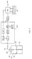
- Figure 1 shows an embodiment of an inventive Device for carrying out a method according to the invention for distance measurement, especially for level measurement.
- the measuring principle of the device shown in Figure 1 is based on the measurement of signal propagation times, respectively the measurement of delay times between the transmission of a Measurement signal and the reception of a reflected signal, or echo signal.
- a waveguide 30 which as a coaxial line, Single wire or two-wire line and can be from top to bottom in the container 10 extends.
- a Connection arrangement provided for attaching the waveguide 30 on the container 10 and for connecting the waveguide to a connecting line 40 to a transmission and SAE receiving unit is used.
- the container serves to store a medium 20, in particular a liquid or bulk material whose level is in Figure 1 is identified by the reference numeral 21. about there is another medium in the liquid, in particular a gas, for example air.
- the connecting line 40 Transmitter and receiver unit SAE connected, which one for Level measurement by means of the device shown Microwave signal on the connecting line 40 provides and which an echo signal, which from reflections of the transmission signal results in the waveguide 30, via the connecting line 40 receives and as prepared Echo signal ES available at an output terminal AK provides.
- SAE Transmitter and receiver unit
- Such a transmitting and receiving unit SAE for delivering a Transmission pulse, for receiving reflected pulses and for Formation of an echo signal from the reflected pulses and a first reference signal is known from DE 42 40 491 C2, expressly refer to their description here becomes.
- Such a transmitting and receiving unit SAE has a first oscillator OSZ1, which is driven by a Sequence control AS provides a transmission pulse, which via a circulator and the connecting line 40 in the waveguide 30 is coupled. Part of the performance the transmit pulse is via the circulator ZI to the amplifier AMP supplied, the amplifier AMP a mixer with a Multiplier MUL and a second oscillator OSZ2 connected is that from the high-frequency amplifier output signal generates an echo signal ES with a lower frequency.
- the amplifier AMP and the mixer MUL, OSZ2 also reflected in the waveguide 30 Pulses ES supplied.
- the circulator is therefore superimposed the signal consisting of the reflected pulses on off the first reference pulse derived from the transmission pulse for formation of the echo signal ES.
- the output terminal AK of the transmitting and receiving unit SAE is according to the invention an analog-digital converter and an evaluation unit AE downstream with a memory SP, their function is explained in more detail.
- an echo signal ES is sent to a device unfilled container 10 generated and as a second reference signal after an analog-to-digital conversion in the storage unit SP saved.
- An echo signal which when filled Container 10 is generated differs from that Echo signal for an empty container by at least one additional pulse resulting from the reflection of the transmission pulse at the interface 21 between the liquid 22 and the gas 20 results.
- the level is determined with the echo signal determine in the container 10.
- Fig. 2 shows a typical waveform of one at empty container 10 determined echo signal, which is the second Reference signal RS2 is used.
- This signal is initially if there are no reflected signals from the waveguide 30 are received at a low level and then assigns a second reference pulse P21, which is the delivery of the Indicates transmission pulse to the waveguide 30 and the in the circulator ZI, when the transmission pulse is sent, the echo signal is superimposed.
- the next striking point in the The course of the second reference signal RS2 is a negative pulse P22, which results from a reflection of the transmission pulse on the Waveguide 30 at the transition from the connecting line 40 results on the waveguide 30.
- Another - in Figure 2 negative pulse P23 of the second reference signal RS2 results from a reflection of the transmission pulse at the end of the open Waveguide 30. This pulse P23 can depend on the Way in which the waveguide enters the container built in, also be positive.
- an echo signal when empty 3 shows an echo signal ES filled container 10.
- This echo signal ES is initially at a low level at which no reflected Receive pulses or signals from waveguide 30 become. Following this approximately constant Area, the echo signal ES has a first reference pulse P31 on which the time of sending the transmission pulse marked and the pulse P21 of the second reference signal RS2 corresponds.
- a later negative pulse P32 results from the reflection of the transmission pulse at the transition between the connecting line 40 and the waveguide 30 and corresponds to the pulse P22 of the second reference signal RS2.
- This Impulse P33 is only for poorly reflecting media, such as for example oil.
- the second reference signal RS2 from the echo signal IT subtracts. The subtraction takes place point by point by subtracting amplitude values that correspond to corresponding temporal positions of the waveforms of the second Reference signal RS2 and the echo signal ES are. there it is assumed that the courses of the signals to be compared, their samples, for example, in the memory arrangement SP are stored, have no temporal offset.
- a time from which the echo signal ES is larger than that second reference signal is RS2 indicates a reflection of the transmission signal at the interface between the liquid 22 and the gas 20.
- An amplitude offset can cause problems with such a procedure of the second reference signal RS2 or the echo signal Prepare IT.
- Amplitude offset referred to here Each case a value by which the echo signal ES and distinguish the second reference signal RS2 from zero, though no reflected signal via the connecting line 40 from the waveguide 30 into the transmitting and receiving unit SAE is coupled.
- the offset of the echo signal ES is shown in Fig. 3 in the period before the first reference signal P31, that is clearly before sending the transmission pulse.
- the inventive method Before the comparison of the echo signal ES and the second reference signal RS2 to determine the temporal position of the reflected Pulse P34 sees the inventive method therefore first of all, the amplitude offset of the second reference signal RS2 and the amplitude offset of the echo signal ES to investigate. The difference between these two amplitude offsets is then from the signal with the larger amplitude offset subtracted or to the signal with the smaller amplitude offset added to an influence of the amplitude offsets when comparing the second reference signal RS2 and to avoid the echo signal ES.
- the method first provides for the maximum of the first reference pulse P31 of the echo signal ES and the maximum of second reference pulse P21 of the second reference signal RS2 to investigate. These maxima represent the first relative Maximum in the waveforms of the second reference signal RS2 and the echo signal ES represent, since both the second reference signal RS2 as well as the echo signal ES before these reference pulses P31, P21, which is a reference for the point in time represent the transmit pulse on an approximately constant and low level.
- a first comparison value V1 and on the curve of the second reference signal RS2 a second comparison value V2 determined, each time by the time period Tv before respective maximum.
- the time period Tv is so long chosen that the times at which the comparative values V1, V2 are determined before the edges of the slope rise first and second reference pulses P31, P21.
- the comparison value V1 represents a measure of the amplitude offset of the echo signal ES and the second comparison value V2 represents a measure of the amplitude offset of the second reference signal RS2, this amplitude offset at the subsequent comparison of the echo signal ES and the second Reference signal RS2 to determine the timing of the on the interface 21 reflected pulse P34 is taken into account become.
- both Echo signal ES and thus also the second reference signal RS2, a noise signal of low amplitude, which is superimposed especially in the approximately constant ranges makes the reference pulses P21, P31 noticeable.
- a noise signal of low amplitude which is superimposed especially in the approximately constant ranges makes the reference pulses P21, P31 noticeable.
- several first comparison values each spaced apart in time are on the echo signal curve ES and a corresponding one Number of second comparison values on the signal curve of the generate second reference signal RS2 and for determination of the respective amplitude offset is the mean of the first To form comparison values and the second comparison values.
- P21 can also determine the comparison values V1, V2 of points on the echo signal curve ES and the second reference signal curve RS2 can be assumed, the time before the Maxima are and their amplitude in a fixed ratio to the associated maximum amplitude value.
- the signal curves are still constant and the rising edge of the reference pulses P31, P21 has not yet been reached, can be started from the maximum values of the first and second reference pulses P31, P21 neighboring each earlier Amplitude values of one of the curves, i.e. the echo signal curve S or the second reference signal curve RS2, with each other be compared.
- the amplitudes of these neighboring ones Points of the signal curves no longer differ from each other, so is the constant range of the signal curves before the reference pulses P21, P31 reached and can be used as a respective comparison value be used.
- the pulse P21 results from the coupling of a reference pulse into the echo signal.
- P32 be caused by the reflection of the transmission signal at the transition between line 40 ( Figure 1) and the waveguide 30 arise. This reflection occurs in everyone by means of the arrangement 1 emitted signal so that the resulting pulses P21, P31 as reference points in the determination of the offset can serve.
- P32 can be based on the coupling of the first reference pulse P21 in the echo signal can be dispensed with, which reduces the circuitry for a circuit arrangement to carry out of the method according to the invention is reduced.
- P32 When using the negative pulses P22, P32 is first the minimum of the pulses P22, P32, or one in a fixed time interval before or after the minimum value, determined on the echo signal curve and the reference signal curve. Based on this value, as explained above, Comparative values to determine the offset on both curves determined.
- the 1 an analog-to-digital converter, which of the output terminals of the transmitting and receiving unit SAE is connected downstream.
- One using the analog-to-digital converter Time-discrete signal formed is an evaluation unit AE supplied to which a storage unit SP with at least two memory locations SP1, SP2 for storing the second reference signal RS2 and an echo signal ES is connected.
- the second reference signal determined when the container 10 is empty RS2 is stored in one of the memories SP1, SP2 and is to determine the fill level with each measurement process compared to an echo signal ES, which is temporarily in the other of the two memories SP2, SP1 is stored.
- the Evaluation unit AE has means for comparing a section of the echo signal stored in the memory SP with a portion of the second stored in the memory SP Reference signal RS2 and to determine the amplitude offset according to the previously described method.
- the one used to carry out the method according to the invention, or stored section of the echo signal ES and the second reference signal RS2 preferably begins one certain period of time before the transmission pulse, i.e. before the first and second reference pulses P31, P21, which the transmission pulse identifies in the echo signal ES and the second reference signal RS, and ends a certain period of time after the signal pulses P23, P33, which in the echo signal ES and the Reference signal RS2 the reflection of the transmission signal on the open Mark the end of the waveguide 30.
- the evaluation unit downstream of the analog-digital converter with the memory SP is preferably a digital signal processor or a commercially available computer that uses the method described taking into account the amplitude offset the echo signal ES and the second reference signal RS2 the time interval between the first reference pulse P31 and the pulse P34 determined and from this time interval in knowledge of the frequency of the transmitted Microwave signal determines the fill level in the container 10.
Landscapes
- Engineering & Computer Science (AREA)
- Radar, Positioning & Navigation (AREA)
- Remote Sensing (AREA)
- Physics & Mathematics (AREA)
- General Physics & Mathematics (AREA)
- Computer Networks & Wireless Communication (AREA)
- Electromagnetism (AREA)
- Thermal Sciences (AREA)
- Fluid Mechanics (AREA)
- Measurement Of Levels Of Liquids Or Fluent Solid Materials (AREA)
- Radar Systems Or Details Thereof (AREA)
Abstract
Description
- Figur 1:
- Ausführungsbeispiel einer erfindungsgemäßen Vorrichtung zur Durchführung eines erfindungsgemäßen Verfahrens;
- Figur 2:
- Signalverlauf eines zweiten Referenzsignals;
- Figur 3:
- Signalverlauf eines Echosignals;
- Figur 4:
- Ausschnittsweise gemeinsame Darstellung von zweitem Referenzsignal und Echosignal zur Ermittlung des Offset.
- AE
- Auswerteeinheit
- AMP
- Verstärker
- AS
- Ablaufsteuerung
- ES
- Echosignal
- MUL
- Multiplizierer
- OSZ1
- erster Oszillator
- OSZ2
- zweiter Oszillator
- P21
- zweiter Referenzimpuls
- P22, P32
- Impuls durch Reflexion an Anfang des Wellenleiters
- P23, P33
- Impuls durch Reflexion am Ende des Wellenleiters
- P31
- erster Referenzimpuls
- P34
- Impuls durch Reflexion an der Grenzfläche 21
- RS2
- zweites Referenzsignal
- SP
- Speicher
- SP1
- erste Speicherzelle
- SP2
- zweite Speicherzelle
- Ts
- zeitlicher Abstand zwischen den Impulsen
- ZI
- Zirkulator
- 10
- Behälter
- 20
- Gas
- 21
- Grenzbereich
- 22
- Flüssigkeit
- 30
- Wellenleiter
- 32
- Anschlussvorrichtung
- 40
- Verbindungsleitung
Claims (9)
- Verfahren zur Entfernungsmessung mittels eines Signals, das in Richtung eines zu messenden Objekts mittels einer Sendeeinrichtung ausgesendet wird, wobei von einer Empfangseinrichtung ein Echosignal (ES) empfangen wird, das einen ersten Referenzimpuls (P21; P22) aufweist, und wobei das Echosignal (ES) mit einem zweiten Referenzsignal (RS2), das einen zweiten Referenzimpuls (P31; P32) aufweist, zur Ermittlung einer Signallaufzeit verglichen wird, und wobei zur Ermittlung eines Amplituden-Offset zwischen dem Echosignal (ES) und dem zweiten Referenzsignal (RS2) ein erster Vergleichswert (V1) des Echosignals (ES) und ein zweiter Vergleichswert des zweiten Referenzsignals (RS2) miteinander verglichen werden, die zeitlich jeweils vor dem ersten und zweiten Referenzimpuls (P21, P31; P22, P32) in einem Bereich der Echosignalkurve und der zweiten Referenzsignalkurve liegen, in denen diese wenigstens annäherungsweise eine Steigung Null aufweisen.
- Verfahren nach Anspruch 1, bei dem dem Echosignal ein erster Referenzimpuls (P21) überlagert ist
- Verfahren nach Anspruch 1 oder 2, bei dem jeweils ein Supremum der Amplitude des ersten Referenzimpulses (P21; P22) und des zweiten Referenzimpulses (P31; P32) ermittelt wird und bei dem jeweils ein Amplitudenwert der Echosignalkurve (ES) und der zweiten Referenzsignalkurve (RS2) als erster und zweiter Vergleichswert (V1, V2) herangezogen wird, der eine vorbestimmte Zeitdauer vor dem jeweiligen Supremum liegt
- Verfahren nach Anspruch 3, bei dem zur Ermittlung des ersten und zweiten Vergleichswerts (V1, V2) anstelle des Supremums des ersten und zweiten Referenzimpulses (P21, P31; P22, P32) jeweils von einem vor dem Supremum liegenden Amplitudenwert ausgegangen wird, der einen vorgegebenen Bruchteil des Supremums des ersten und zweiten Referenzimpulses (P21, P31; P22, P32) beträgt.
- Verfahren nach einem der vorangehenden Ansprüche bei dem mehrere erste Vergleichswerte und mehrere zweite Vergleichswerte gebildet werden, deren Mittelwerte zur Ermittlung des Offset miteinander verglichen werden.
- Verfahren nach Anspruch 1, bei dem jeweils vor dem Supremum des ersten Referenzimpulses (P21; P22) liegende benachbarte Amplitudenwerte miteinander verglichen werden, wobei als erster Vergleichswert ein Amplitudenwert herangezogen wird, bei welchem sich zwei benachbarte Werte nicht mehr unterscheiden, und bei dem jeweils vor dem Supremum des zweiten Referenzimpulses (P31; P32) liegende benachbarte Amplitudenwerte miteinander verglichen werden, wobei als zweiter Vergleichswert ein Amplitudenwert herangezogen wird, bei welchem sich zwei benachbarte Werte nicht mehr unterscheiden.
- Verfahren nach einem der vorangehenden Ansprüche, bei dem zur Ermittlung eines zeitlichen Offset zwischen dem Echosignal und dem zweiten Referenzsignal die zeitlichen Lagen der Suprema des ersten Referenzimpulses (P21; P22) und des zweiten Referenzimpulses (P31; P32) ausgewertet werden.
- Vorrichtung zur Entfernungsmessung mit
einer Sende- und Empfangseinrichtung (SAE) zum Aussenden eines Signals und zum Empfangen eines Echosignals, einer Speichereinrichtung (SP) zum Speichern eines zweiten Referenzsignals, einer Auswerteeinrichtung (AE) zum Vergleichen des Echosignals und des zweiten Referenzsignals,
dadurch gekennzeichnet, dass
die Auswerteeinrichtung zur Ermittlung eines Amplituden-Offset zwischen dem Echosignal (ES) und dem zweiten Referenzsignal (RS2) eine erste Einheit zur Ermittlung eines vor einem ersten Referenzimpuls (P31) des Echosignals (ES) liegenden ersten Vergleichswertes (V1), der sich in einem Signalbereich des Echosignals mit einer Steigung Null befindet, und eine zweite Einheit zur Ermittlung eines vor einem zweiten Referenzimpuls (P21) des Echosignals (ES) liegenden zweiten Vergleichswertes (V2), der sich in einem Signalbereich mit der Steigung Null des zweiten Referenzsignals (RS2) befindet, aufweist. - Vorrichtung nach Anspruch 7, bei welcher die Sende- und Empfangseinrichtung (SAE) dazu ausgebildet ist dem Echosignal (ES) ein erstes Referenzsignal (P31) zu überlagern.
Applications Claiming Priority (2)
| Application Number | Priority Date | Filing Date | Title |
|---|---|---|---|
| DE10044769 | 2000-09-11 | ||
| DE2000144769 DE10044769A1 (de) | 2000-09-11 | 2000-09-11 | Verfahren und Vorrichtung zur Entfernungsmessung |
Publications (3)
| Publication Number | Publication Date |
|---|---|
| EP1186906A2 true EP1186906A2 (de) | 2002-03-13 |
| EP1186906A3 EP1186906A3 (de) | 2003-12-17 |
| EP1186906B1 EP1186906B1 (de) | 2006-08-02 |
Family
ID=7655731
Family Applications (1)
| Application Number | Title | Priority Date | Filing Date |
|---|---|---|---|
| EP20010121868 Expired - Lifetime EP1186906B1 (de) | 2000-09-11 | 2001-09-11 | Verfahren und Vorrichtung zur Entfernungsmessung |
Country Status (2)
| Country | Link |
|---|---|
| EP (1) | EP1186906B1 (de) |
| DE (2) | DE10044769A1 (de) |
Cited By (4)
| Publication number | Priority date | Publication date | Assignee | Title |
|---|---|---|---|---|
| FR2834071A1 (fr) * | 2002-12-17 | 2003-06-27 | Liquip Sales Pty Ltd | Sonde pour capteur radar de niveau de liquide |
| AU2002313365B2 (en) * | 2001-12-20 | 2007-05-31 | Liquip International Pty Limited | A probe for a liquid level sensor |
| WO2018086949A1 (de) * | 2016-11-11 | 2018-05-17 | Leoni Kabel Gmbh | Verfahren und messanordnung zur überwachung einer leitung |
| EP2226615B1 (de) * | 2009-03-02 | 2018-08-22 | VEGA Grieshaber KG | Messen von Füllständen mittels Auswerten einer Echokurve |
Families Citing this family (2)
| Publication number | Priority date | Publication date | Assignee | Title |
|---|---|---|---|---|
| EP2626676B1 (de) | 2012-02-08 | 2016-04-20 | VEGA Grieshaber KG | Vorrichtung und Verfahren zum Korrigieren eines Offsets |
| EP4227651B1 (de) * | 2022-02-15 | 2024-11-20 | VEGA Grieshaber KG | Verfahren zum automatisierten erstellen einer kompensationsechokurve |
Family Cites Families (5)
| Publication number | Priority date | Publication date | Assignee | Title |
|---|---|---|---|---|
| DE4223346C2 (de) * | 1992-07-16 | 1996-05-02 | Grieshaber Vega Kg | Anordnung und Verfahren zur berührungslosen Füllstandmessung |
| DE4240491C2 (de) * | 1992-12-02 | 1996-10-31 | Grieshaber Vega Kg | Vorrichtung zur Laufzeitmessung, insbesondere Entfernungsmessung |
| DE4332071C2 (de) * | 1993-09-21 | 1995-09-07 | Endress Hauser Gmbh Co | Verfahren zur Füllstandsmessung nach dem Radarprinzip |
| DE4405238C2 (de) * | 1994-02-18 | 1998-07-09 | Endress Hauser Gmbh Co | Anordnung zur Messung des Füllstands in einem Behälter |
| US5884231A (en) * | 1995-12-21 | 1999-03-16 | Endress & Hauser Gmbh & Co. | Processor apparatus and method for a process measurement signal |
-
2000
- 2000-09-11 DE DE2000144769 patent/DE10044769A1/de not_active Ceased
-
2001
- 2001-09-11 DE DE50110592T patent/DE50110592D1/de not_active Expired - Lifetime
- 2001-09-11 EP EP20010121868 patent/EP1186906B1/de not_active Expired - Lifetime
Cited By (5)
| Publication number | Priority date | Publication date | Assignee | Title |
|---|---|---|---|---|
| AU2002313365B2 (en) * | 2001-12-20 | 2007-05-31 | Liquip International Pty Limited | A probe for a liquid level sensor |
| FR2834071A1 (fr) * | 2002-12-17 | 2003-06-27 | Liquip Sales Pty Ltd | Sonde pour capteur radar de niveau de liquide |
| EP2226615B1 (de) * | 2009-03-02 | 2018-08-22 | VEGA Grieshaber KG | Messen von Füllständen mittels Auswerten einer Echokurve |
| WO2018086949A1 (de) * | 2016-11-11 | 2018-05-17 | Leoni Kabel Gmbh | Verfahren und messanordnung zur überwachung einer leitung |
| US11041899B2 (en) | 2016-11-11 | 2021-06-22 | Leoni Kabel Gmbh | Method and measuring assembly for monitoring a line |
Also Published As
| Publication number | Publication date |
|---|---|
| EP1186906B1 (de) | 2006-08-02 |
| EP1186906A3 (de) | 2003-12-17 |
| DE10044769A1 (de) | 2002-04-04 |
| DE50110592D1 (de) | 2006-09-14 |
Similar Documents
| Publication | Publication Date | Title |
|---|---|---|
| DE19723646C2 (de) | Verfahren zur Messung des Füllstands eines Füllguts in einem Behälter nach dem Radarprinzip | |
| DE69530863T2 (de) | Elektronischer vielzweck-füllstandsensor | |
| DE102012101725A1 (de) | Verfahren zur Füllstandsmessung | |
| EP2652462B1 (de) | Messvorrichtung, steuervorrichtung und messgerät zur füllstandmessung | |
| DE2649075C3 (de) | Verfahren und Anordnung zur Messung des Füllstandes in einem Behälter bzw. der Schüttguthöhe auf einem Lagerplatz | |
| EP0337293B1 (de) | Füllstandsmessgerät | |
| DE60034631T2 (de) | Erkennung der schnittstelle zwischen mehreren prozess-produkten für ein füllstandmess-radargerät mit niedriger leistung | |
| EP0670048B1 (de) | Verfahren zur füllstandsmessung nach dem radarprinzip | |
| DE3438045A1 (de) | Verfahren und anordnung zur signaluebertragung bei ultraschall-echolotgeraeten | |
| EP0573034A2 (de) | Verfahren und Anordnung zur Abstandsmessung nach dem Impulslaufzeitprinzip | |
| DE112006002310T5 (de) | Verarbeitung des Tanksignals in einem Radarfüllstandsmesssystem | |
| WO2013092099A1 (de) | Verfahren und messgerät zur füllstandsmessung | |
| DE4234300C2 (de) | Füllstand-Meßverfahren | |
| DE102013107847A1 (de) | Verfahren zur Ermittlung und Überwachung des Füllstands eines Mediums in einem Behälter nach einem Laufzeitmessverfahren | |
| DE10226347C1 (de) | Verfahren und Schaltungsanordnung zum Ermitteln von Übertragungsparametern | |
| DE60118586T2 (de) | Verfahren und vorrichtung zur leitungsdämpfungsmessung | |
| EP1186906B1 (de) | Verfahren und Vorrichtung zur Entfernungsmessung | |
| DE4301341C1 (de) | Verfahren und Schaltungsanordnung zum Bestimmen des zeitlichen Anfangs eines Impulssignals | |
| DE102020134379A1 (de) | Leitfähigkeits-Messung | |
| DE102004028547A1 (de) | Vorrichtung zur Bestimmung des Füllstandes in einem Tank | |
| DE19935646A1 (de) | Vorrichtung zur Bestimmung des Füllstandes eines Füllguts in einem Behälter | |
| DE10309861B4 (de) | Verfahren und Vorrichtung zur Bestimmung wenigstens einer chemischen oder physikalischen Eigenschaft einer Flüssigkeit bei Füllstandsmessung in einem Behälter | |
| EP2739946B1 (de) | Lineares verhältnis zwischen tracks | |
| DE102016213324B3 (de) | Füllstandsmessgerät nach dem Zeitbereichsreflektometrie-Prinzip sowie Verfahren zum Betreiben eines solchen Füllstandsmessgeräts | |
| EP1039273A2 (de) | Verfahren zur Füllstandsmessung |
Legal Events
| Date | Code | Title | Description |
|---|---|---|---|
| PUAI | Public reference made under article 153(3) epc to a published international application that has entered the european phase |
Free format text: ORIGINAL CODE: 0009012 |
|
| AK | Designated contracting states |
Kind code of ref document: A2 Designated state(s): AT BE CH CY DE DK ES FI FR GB GR IE IT LI LU MC NL PT SE TR |
|
| AX | Request for extension of the european patent |
Free format text: AL;LT;LV;MK;RO;SI |
|
| PUAL | Search report despatched |
Free format text: ORIGINAL CODE: 0009013 |
|
| AK | Designated contracting states |
Kind code of ref document: A3 Designated state(s): AT BE CH CY DE DK ES FI FR GB GR IE IT LI LU MC NL PT SE TR |
|
| AX | Request for extension of the european patent |
Extension state: AL LT LV MK RO SI |
|
| 17P | Request for examination filed |
Effective date: 20040506 |
|
| 17Q | First examination report despatched |
Effective date: 20040603 |
|
| AKX | Designation fees paid |
Designated state(s): DE FR GB |
|
| GRAP | Despatch of communication of intention to grant a patent |
Free format text: ORIGINAL CODE: EPIDOSNIGR1 |
|
| GRAS | Grant fee paid |
Free format text: ORIGINAL CODE: EPIDOSNIGR3 |
|
| GRAA | (expected) grant |
Free format text: ORIGINAL CODE: 0009210 |
|
| AK | Designated contracting states |
Kind code of ref document: B1 Designated state(s): DE FR GB |
|
| REG | Reference to a national code |
Ref country code: GB Ref legal event code: FG4D Free format text: NOT ENGLISH |
|
| REF | Corresponds to: |
Ref document number: 50110592 Country of ref document: DE Date of ref document: 20060914 Kind code of ref document: P |
|
| GBT | Gb: translation of ep patent filed (gb section 77(6)(a)/1977) |
Effective date: 20061016 |
|
| ET | Fr: translation filed | ||
| PLBE | No opposition filed within time limit |
Free format text: ORIGINAL CODE: 0009261 |
|
| STAA | Information on the status of an ep patent application or granted ep patent |
Free format text: STATUS: NO OPPOSITION FILED WITHIN TIME LIMIT |
|
| 26N | No opposition filed |
Effective date: 20070503 |
|
| PGFP | Annual fee paid to national office [announced via postgrant information from national office to epo] |
Ref country code: GB Payment date: 20140923 Year of fee payment: 14 |
|
| PGFP | Annual fee paid to national office [announced via postgrant information from national office to epo] |
Ref country code: FR Payment date: 20140917 Year of fee payment: 14 |
|
| GBPC | Gb: european patent ceased through non-payment of renewal fee |
Effective date: 20150911 |
|
| REG | Reference to a national code |
Ref country code: FR Ref legal event code: ST Effective date: 20160531 |
|
| PG25 | Lapsed in a contracting state [announced via postgrant information from national office to epo] |
Ref country code: GB Free format text: LAPSE BECAUSE OF NON-PAYMENT OF DUE FEES Effective date: 20150911 |
|
| PG25 | Lapsed in a contracting state [announced via postgrant information from national office to epo] |
Ref country code: FR Free format text: LAPSE BECAUSE OF NON-PAYMENT OF DUE FEES Effective date: 20150930 |
|
| PGFP | Annual fee paid to national office [announced via postgrant information from national office to epo] |
Ref country code: DE Payment date: 20180924 Year of fee payment: 18 |
|
| REG | Reference to a national code |
Ref country code: DE Ref legal event code: R119 Ref document number: 50110592 Country of ref document: DE |
|
| PG25 | Lapsed in a contracting state [announced via postgrant information from national office to epo] |
Ref country code: DE Free format text: LAPSE BECAUSE OF NON-PAYMENT OF DUE FEES Effective date: 20200401 |