EP1186859A2 - Vorrichtung zum lotrechten Ausrichten eines geodätischen Gerätes - Google Patents
Vorrichtung zum lotrechten Ausrichten eines geodätischen Gerätes Download PDFInfo
- Publication number
- EP1186859A2 EP1186859A2 EP01120226A EP01120226A EP1186859A2 EP 1186859 A2 EP1186859 A2 EP 1186859A2 EP 01120226 A EP01120226 A EP 01120226A EP 01120226 A EP01120226 A EP 01120226A EP 1186859 A2 EP1186859 A2 EP 1186859A2
- Authority
- EP
- European Patent Office
- Prior art keywords
- target
- laser
- axis
- optical
- target axis
- Prior art date
- Legal status (The legal status is an assumption and is not a legal conclusion. Google has not performed a legal analysis and makes no representation as to the accuracy of the status listed.)
- Granted
Links
- 230000003287 optical effect Effects 0.000 claims abstract description 53
- 230000008878 coupling Effects 0.000 claims abstract description 30
- 238000010168 coupling process Methods 0.000 claims abstract description 30
- 238000005859 coupling reaction Methods 0.000 claims abstract description 30
- 230000000007 visual effect Effects 0.000 claims abstract description 7
- 230000008685 targeting Effects 0.000 abstract description 2
- 229910000679 solder Inorganic materials 0.000 description 15
- 230000000712 assembly Effects 0.000 description 3
- 238000000429 assembly Methods 0.000 description 3
- 230000008859 change Effects 0.000 description 2
- 238000010276 construction Methods 0.000 description 2
- 238000005476 soldering Methods 0.000 description 2
- 230000006735 deficit Effects 0.000 description 1
- 238000006073 displacement reaction Methods 0.000 description 1
- 230000007613 environmental effect Effects 0.000 description 1
- 230000036541 health Effects 0.000 description 1
- 239000003550 marker Substances 0.000 description 1
- 238000005259 measurement Methods 0.000 description 1
- 230000007246 mechanism Effects 0.000 description 1
- 238000000034 method Methods 0.000 description 1
- 230000008569 process Effects 0.000 description 1
Images
Classifications
-
- G—PHYSICS
- G01—MEASURING; TESTING
- G01C—MEASURING DISTANCES, LEVELS OR BEARINGS; SURVEYING; NAVIGATION; GYROSCOPIC INSTRUMENTS; PHOTOGRAMMETRY OR VIDEOGRAMMETRY
- G01C15/00—Surveying instruments or accessories not provided for in groups G01C1/00 - G01C13/00
- G01C15/10—Plumb lines
- G01C15/105—Optical plumbing
Definitions
- the invention relates to a device for the vertical alignment of a geodetic device above a ground point.
- geodetic devices such as Tachymeter or theodolites
- a geodetic benchmark can be centered.
- the accessories, including reflectors or target plates, above a floor point be aligned, with a perpendicular for the most accurate measurement possible Alignment of the standing axis to the plane in which the ground point is required lies.
- Many are used as aids for vertical alignment to a ground point optical solders used. These usually include an observation facility, for example in the form of a small telescope with which the bottom point is targeted.
- the optical axis of the observation device is defined aligned with the vertical axis of the geodetic device or is identical to it.
- an optical marking is often coupled into the observation beam, which, depending on the mode of operation, must be aligned with the floor point or this features.
- the position of the geodetic device is over changed the bottom point until the desired match is reached is.
- the position of the geodetic device becomes the ground point certainly. Due to the defined position of the target beam to the geodetic device this is then in a precisely determinable position to the ground point.
- Such optical solders are usually installed directly in the geodetic devices.
- tachymeters or theodolites that are inserted into a tripod, it is also possible to use the tripod or its first with separate soldering equipment Pick-up mechanism for the tachymeter or theodolite to be coupled center over a ground point, then remove the soldering tool and to be replaced by the tachymeter or theodolite.
- the invention is based on the object of a device to create the kind mentioned in the beginning, which is accurate under all visual conditions Alignment of the geodetic device allowed above the ground point.
- a device comprising an optical observation device for the visual targeting of the ground point with a in spatial defined position to the geodetic device extending target beam, a laser device to generate a spatially defined position to the device Laser beam and an optical coupling element over which the laser beam and the aiming beam into a joint aligned vertically above the ground point optical target axis can be coupled.
- the device according to the invention can also be used under unfavorable lighting conditions and visibility conditions in a simple way an exact alignment of the realize geodetic device. So in poor visibility conditions Alignment of the device via the laser beam coupled into the target axis. at extreme ambient brightness, however, can be aligned via the optical Observation device by coupling the target beam into the target axis, without the need for a more powerful laser in this case.
- the position of the optical coupling element is switchable between two positions within the geodetic device. In a first position, only the target beam is in the target axis coupled, whereas in the second position only the laser beam in the target axis is coupled.
- the geodetic device is thus aligned either by means of the optical one Observation device or, after switching over the coupling element from one position to the other using the laser device laser spots generated in the target plane in which the ground point is located. For a particularly simple handling of this switchover, the switching on and switching off the laser device immediately after switching the optical Coupling element are bound.
- the coupling element is preferably a prism, which has a first reflection surface for coupling the target beam into the target axis and a second reflection surface for coupling the laser beam into the target axis.
- the prism opposite the geodetic device movably arranged.
- the observation device and the laser device with the interposition of the prism in a common Sleeve arranged.
- the sleeve is opposite along its longitudinal axis the geodetic device is axially movable. Furthermore, it is ensured that in two defined end positions of the adjustment path of the sleeve an orientation of the sleeve to the geodetic device is guaranteed.
- These two end positions of the sleeve are with the two switching positions of the optical coupling element, d. H. for example of the prism, linked so that between the axial movement of the sleeve the mode of operation as a laser solder and the mode of operation as an optical solder are selected can.
- Components in a common sleeve can be pre-assembled as a module and used in various ways in different geodetic devices.
- the modular structure also allows a particularly precise alignment of the target beam and the laser beam with respect to the target axis. Centering on that geodetic device then takes place via the storage of the sleeve.
- the target beam and the laser beam is oriented in the direction of the longitudinal axis of the sleeve, whereas the target axis is at right angles to the longitudinal axis of the sleeve.
- the coupling element as a pivotable mirror form the target beam or the laser beam at a first setting angle couples into the target axis and at a second setting angle each correspondingly directs another beam into the target axis.
- the mirror can be used as Rotating mirror or be designed as a folding mirror. In the latter case, the Mirror at the first setting angle either the target beam or the laser beam while the other beam is interrupted. At the second setting angle the interrupted beam then becomes deflected into the target axis coupled in, whereas the other beam is blocked.
- the coupling element is designed as a fixed, Optical deflection device oriented in a defined manner to the geodetic device formed with an optically selective layer.
- it is optical selective layer for daylight hitting at a given angle, permeable in the visual area, however, for under a different one Reflecting angles of laser light.
- the reverse is in a second embodiment the optically selective layer for at an oblique angle of incidence incident light reflecting in the visual area, however, for under the laser light incident at the same oblique angle of incidence.
- the laser beam coupled into the target axis or the projected one serves Spot of light as a marker to align with the point on the ground is.
- a separate alignment mark for example a Crosshair, be dispensed with, so that the construction of the device accordingly can be simplified.
- the laser beam can start from the laser source like the target axis also be aligned vertically and so without the need to change direction be coupled directly into the target axis. It is also possible, the laser beam as well as the target beam on the optical coupling element to couple into the target axis from an orthogonal direction.
- the laser source can be arranged on the same side of the geodetic device be on which the assemblies of the optical observation device are located.
- the laser source can be there either below or above it Assemblies may be arranged so that there is an optimal one for the designer Device construction can be found.
- the laser beam orthogonal to the target axis also with the target beam orthogonal to the target axis when viewed in the direction of the Target axis encloses an angle ⁇ 0 °.
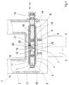
- the first exemplary embodiment in FIG. 1 shows a geodetic device in the form of a Tachymeter 1, here only a lower section of a support 2 of the tachymeter 1 is shown in more detail.
- a geodetic device in the form of a Tachymeter 1
- a support 2 of the tachymeter 1 Via one provided on the underside of the support 2 Plug pin 3, the tachymeter 1 in a base, for example one Use a tripod or a tripod.
- the plug 3 takes over one Centering function.
- a device for the vertical alignment of the tachymeter 1 is provided at a bottom point, which is both an optical plumb and a Includes laser solder.
- This device here forms a self-contained module 4, that is inserted into the support 2 and exactly aligned to this, so that one on the optical target axis Z to be aligned with the ground, a centering of the tachymeter 1 allowed on a vertical above the ground point.
- the module 4 is attached via a bearing sleeve 5 to an axle actuator 6, which in turn with a pivot pin 7 in a socket 8 provided on the support 2 the target axis Z rotatably supported and axially supported in the direction of the target axis Z. is.
- a further sleeve 9 is arranged, whose longitudinal axis runs orthogonal to the target axis Z.
- the sleeve 9 is inside the bearing sleeve 5 slidably guided along its longitudinal axis. It serves as a holder for an optical observation device 10 and a laser device 11, which here arranged coaxially to each other and by a also lying in the sleeve 9 optical coupling element 12 are separated from each other.
- This optical coupling element 12 is via the sleeve 9 to the other functional elements of the tachymeter 1 exactly aligned and couples the target beam B the optical observation device 10 as well as the laser beam L of the laser device 11 into the target axis Z to be aligned vertically above a ground point.
- the optical observation device 10 comprises one arranged in the sleeve 9 optical telescope with an observation lens 13, a field lens 14 with a Alignment mark in the form of a crosshair and an eyepiece 15.
- the crosshair can also have other geometric patterns, for example grids or line scales can be used as an alignment mark, are visually perceptible through the eyepiece 15.
- the laser device arranged coaxially to the optical observation device 10 11 comprises a laser diode 16 positioned on the longitudinal axis of the sleeve 9, the purpose of supplying an operating voltage with one at the end of the sleeve 9 arranged circuit board 17 of the laser diode 16 is connected. Furthermore, the Laser device 11 a projection objective 18 for the laser beam L.
- the laser beam L as well as the target beam B strike the optical coupling element 12, which is designed here in the form of a prism 19 to be taken into account.
- This Prism 19 has two inclined at an angle of 45 ° to the target axis Z. Reflective surfaces. A first reflection surface faces the optical observation device 10 and the second, opposite reflection surface the laser device 11, the two reflection surfaces being at an angle of 90 ° to one another lock in.
- the reflecting surfaces guide the target beam B and the laser beam L in to the target axis Z parallel beam paths around.
- the longitudinal axis of the target beam B can be in the target axis Z are coupled. This state is shown in Fig.1.
- the sleeve 9 is shifted to the right in FIG achievable second end position of the laser beam L can be coupled into the target axis Z.
- the sleeve 9 and the bearing sleeve 5 each have suitable light passage openings 26 on.
- An axial displacement of the sleeve can thus be used between one mode of operation switch as an optical solder and an operating mode as a laser solder. This is only pull the sleeve 9 into the desired position. It is still there possible to switch the laser device 11 on and off at the position of the sleeve 9 to couple in the bearing sleeve 5, so that only then operating voltage the laser diode 16 is placed when the prism 19 is in a position for coupling of the laser beam L is in the target axis Z.
- axial stops are provided between the sleeve 9 and the bearing sleeve 5, so that the two switching positions easily and safely by manual shifting the sleeve 9 can be adjusted.
- the outside is for this purpose the sleeve 9 a stop pin 20 is provided, which in a on the bearing sleeve 5th trained longitudinal groove 21 is guided.
- a corresponding vote of Width or the diameter of the stop pin 20 and the width of the longitudinal groove 21 can the stop pin 20 at the same time as a safeguard against rotation of the Serve sleeve 9 opposite the bearing sleeve 5.
- an access opening 22 is provided, which during normal operation of the Tachymeters 1 is covered by a closure, not shown here.
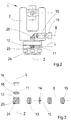
- FIG. 2 shows a second exemplary embodiment of the device according to the invention for the vertical alignment of a geodetic device over a ground point, where the geodetic device is again a tachymeter 1.
- the device also includes an optical observation device 10 and a laser device 11 whose beams B and L are different from the first Embodiment on a fixed optical coupling element 12, the the geodetic device or tachymeter 1 is aligned, simultaneously in the target axis Z to be aligned with the ground point is coupled.
- the coupling element 12 is a divider cube 23 with an optically selective one Layer 24 formed, which reflects the laser light, but the light in visible area.
- both the target beam B and the laser beam are L arranged orthogonally to the target axis Z, the optical observation device 10 with the eyepiece 15 arranged above the laser device 11 is.
- To deflect the target beam B onto the divider cube 23 includes the optical Observation device 10 arranged in the extension of the target axis Z.
- Optical deflecting element 25, for example as a deflecting mirror or as Prism can be formed.
- the divider cube 23 lies in the intersection of the target axis Z and the target beam B.
- the laser beam L is coupled in from a Direction in continuation of the target axis Z through the divider cube 23.
- the laser device 16 can be arranged coaxially to the target axis Z with its laser diode 16 become.
- the laser diode 16 on a plane orthogonal to the target axis Z. Align axis and the laser beam L corresponding to the target beam B in Fig.2 to divert to the divider cube 23. Its selective layer 24 is in the third embodiment, however, such that the laser light through the Layer 24 passes unaffected, but the light in the visible range the target axis Z is reflected in the direction of the target beam B.
- the optical observation device 10 and the laser device 1 can be used a fixed optical coupling element 12, the optical observation device 10 and the laser device 1 spatially relatively freely to each other to be ordered.
- the tachymeter 1 shown in FIG the optical observation device 10 in the support 2 of the tachymeter 1
- the laser device 11 in a section of a not shown here Base which can be designed, for example, as a tripod or tripod, is arranged.
- the optical observation device 10 in the base and the laser device 11 in the support 2 or both assemblies can be arranged together within the support 2 or within the base.
- the devices shown in Fig. 2 and Fig. 3 can be used as a function of use the brightness conditions as an optical solder or as a laser solder. It is also possible to generate the laser device 11 in the target plane To target light spot on the observation device 10, so that a very precise control of the correspondence of the light spot with the ground point possible is.
- the light spot can also be used as an alignment mark in these cases be, so that in a simplified embodiment, one in the target beam B or the target axis Z is otherwise preferred for the mode of operation as an optical solder alignment mark to be coupled can be omitted.
- the exemplary embodiments described above enable precise alignment of a geodetic device to a ground point regardless of the Brightness of the environment.
- the geodetic device remains in its Compact dimensions. You can also use a stronger laser avoid.
Landscapes
- Physics & Mathematics (AREA)
- Engineering & Computer Science (AREA)
- General Physics & Mathematics (AREA)
- Radar, Positioning & Navigation (AREA)
- Remote Sensing (AREA)
- Length Measuring Devices By Optical Means (AREA)
- Telescopes (AREA)
Abstract
Description
- Fig.1
- ein erstes Ausführungsbeispiel einer Vorrichtung zum lotrechten Ausrichten eines geodätischen Gerätes zu einem Bodenpunkt in einer Teilschnittdarstellung,
- Fig.2
- ein zweites Ausführungsbeispiel einer solchen Vorrichtung in einer Teilschnittdarstellung, und in
- Fig.3
- ein drittes Ausführungsbeispiel, wobei hier lediglich eine optische Beobachtungseinrichtung, eine Lasereinrichtung sowie ein optisches Einkoppelelement in bezug auf einen Zielstrahl, einen Laserstrahl und eine Zielachse schematisch dargestellt sind.
Claims (10)
- Vorrichtung zum lotrechten Ausrichten eines geodätischen Gerätes über einem Bodenpunkt, umfassendeine optische Beobachtungseinrichtung (10) zur visuellen Anzielung des Bodenpunktes mittels eines Zielstrahls (B),eine Lasereinrichtung (11) zur Erzeugung eines Laserstrahls (L) undein optisches Einkoppelelement (12), über das der Laserstrahl (L) und der Zielstrahl (B) in eine auf den Bodenpunkt lotrecht auftreffende optische Zielachse (Z) einkoppelbar sind.
- Vorrichtung nach Anspruch 1, dadurch gekennzeichnet, daß das optische Einkoppelelement (12) umschaltbar ist zwischen einer ersten Stellung, in welcher der Zielstrahl (B) in die Zielachse (Z) eingekoppelt ist und einer zweiten Stellung, in welcher der Laserstrahl (L) in die Zielachse (Z) eingekoppelt ist.
- Vorrichtung nach Anspruch 2, dadurch gekennzeichnet, daß das Einkoppelelement (12) ein Prisma (19) ist, das eine erste Reflexionsfläche zur Einkopplung des Zielstrahls (B) in die Zielachse (Z) und eine zweite Reflexionsfläche zur Einkopplung des Laserstrahls (L) in die Zielachse (Z) aufweist.
- Vorrichtung nach Anspruch 3, dadurch gekennzeichnet, daß die Beobachtungseinrichtung (10) und die Lasereinrichtung (11) unter Zwischenschaltung des Prismas (19) gemeinsam in einer Hülse (9) angeordnet sind, wobei die Hülse (9) entlang ihrer Längsachse bewegbar ist und in zwei Endlagen ihres Verstellweges definiert zu der Zielachse (Z) ausgerichtet ist.
- Vorrichtung nach Anspruch 4, dadurch gekennzeichnet, daß der Zielstrahl (B) und der Laserstrahl (L) in Richtung der Längsachse der Hülse (9) ausgerichtet sind und die Zielachse (Z) einen rechten Winkel zur Längsachse der Hülse (9) einnimmt.
- Vorrichtung nach Anspruch 1 oder 2, dadurch gekennzeichnet, daß das Einkoppelelement (12) ein um eine Drehachse schwenkbarer Spiegel ist, der unter einem ersten Einstellwinkel entweder den Zielstrahl (B) oder den Laserstrahl (L) in die Zielachse (Z) einkoppelt und unter einem zweiten Einstellwinkel den jeweils entsprechenden anderen Strahl in die Zielachse (Z) einkoppelt.
- Vorrichtung nach Anspruch 1, dadurch gekennzeichnet, daß das Einkoppelelement (12) eine relativ zu dem geodätischen Gerät feststehend ausgerichtete optische Umlenkeinrichtung mit einer optisch selektiven Schicht (24) ist, wobei die Schicht (24) entweder für unter einem schrägen Einfallswinkel auftreffendes Licht im visuellen Bereich durchlässig, jedoch für unter diesem Einfallswinkel auftreffendes Laserlicht reflektierend ist, oder aber für unter einem schrägen Einfallswinkel auftreffendes Licht im visuellen Bereich reflektierend, jedoch für auftreffendes Laserlicht durchlässig ist.
- Vorrichtung nach Anspruch 6 oder 7, dadurch gekennzeichnet, daß der Zielstrahl (B) und die Zielachse (Z) orthogonal zueinander angeordnet sind.
- Vorrichtung nach einem der Ansprüche 6 bis 8, dadurch gekennzeichnet, daß der Laserstrahl (L) und die Zielachse (Z) orthogonal zueinander angeordnet sind.
- Vorrichtung nach einem der Ansprüche 1 bis 9, dadurch gekennzeichnet, daß in dem Zielstrahl (B) eine zu dem Bodenpunkt auszurichtende Strichmarke angeordnet ist.
Applications Claiming Priority (2)
| Application Number | Priority Date | Filing Date | Title |
|---|---|---|---|
| DE10045807A DE10045807C1 (de) | 2000-09-07 | 2000-09-07 | Vorrichtung zum lotrechten Ausrichten eines geodätischen Gerätes |
| DE10045807 | 2000-09-07 |
Publications (3)
| Publication Number | Publication Date |
|---|---|
| EP1186859A2 true EP1186859A2 (de) | 2002-03-13 |
| EP1186859A3 EP1186859A3 (de) | 2004-02-25 |
| EP1186859B1 EP1186859B1 (de) | 2006-10-04 |
Family
ID=7656417
Family Applications (1)
| Application Number | Title | Priority Date | Filing Date |
|---|---|---|---|
| EP01120226A Expired - Lifetime EP1186859B1 (de) | 2000-09-07 | 2001-08-23 | Vorrichtung zum lotrechten Ausrichten eines geodätischen Gerätes |
Country Status (4)
| Country | Link |
|---|---|
| US (1) | US6724471B2 (de) |
| EP (1) | EP1186859B1 (de) |
| JP (1) | JP3084531U (de) |
| DE (2) | DE10045807C1 (de) |
Families Citing this family (11)
| Publication number | Priority date | Publication date | Assignee | Title |
|---|---|---|---|---|
| US7278218B2 (en) * | 2003-06-18 | 2007-10-09 | Irwin Industrial Tool Company | Laser line generating device with swivel base |
| JP3840119B2 (ja) * | 2002-02-08 | 2006-11-01 | 株式会社ソキア | レーザ求心装置 |
| US6871408B2 (en) * | 2002-03-01 | 2005-03-29 | Irwin Industrial Tool Company | Manual leveling rotating laser with swivel head |
| DE10218441C1 (de) * | 2002-04-25 | 2003-05-22 | Matthias Fuhrland | Einrichtung zur Lage- und Richtungsbestimmung von Kanalein- und Kanalabläufen in Abwasserschächten |
| US7269907B2 (en) * | 2003-07-01 | 2007-09-18 | Irwin Industrial Tool Company | Laser line generating device with swivel base |
| US7487596B2 (en) * | 2004-06-25 | 2009-02-10 | Irwin Industrial Tool Company | Laser line projected on an edge of a surface |
| US7178250B2 (en) * | 2004-07-21 | 2007-02-20 | Irwin Industrial Tool Company | Intersecting laser line generating device |
| US7392592B2 (en) | 2005-10-07 | 2008-07-01 | Milwaukee Electric Tool Corporation | Ruggedized laser level |
| DE202011100603U1 (de) * | 2011-05-12 | 2011-07-12 | Trimble Jena Gmbh | Optisches Lot zur Verwendung in der Geodäsie |
| US20140362170A1 (en) * | 2012-02-15 | 2014-12-11 | Thomson Licensing | Video conference system and method for maintaining participant eye contact |
| DE102012011518B3 (de) * | 2012-06-08 | 2013-10-17 | Trimble Jena Gmbh | Geodätisches ziel und positionsbestimmungssystem |
Family Cites Families (8)
| Publication number | Priority date | Publication date | Assignee | Title |
|---|---|---|---|---|
| DE4007245C2 (de) * | 1990-03-08 | 1999-10-14 | Leica Geosystems Ag | Einrichtung zum Zentrieren eines geodätischen Instrumentes über einem definierten Bodenpunkt |
| US5491555A (en) * | 1993-12-21 | 1996-02-13 | Romine; Michael L. | Measurement referencing and transferring instrument |
| US5501018A (en) * | 1994-07-22 | 1996-03-26 | Porter; Sonney J. | Tribrach device |
| DE29603681U1 (de) * | 1996-02-29 | 1996-04-18 | Carl Zeiss Jena Gmbh, 07745 Jena | Optische Loteinrichtung für geodätische Geräte |
| US5949548A (en) * | 1997-01-22 | 1999-09-07 | Asahi Kogaku Kogyo Kabushiki Kaisha | Height sensing measurement device |
| DE19716304C1 (de) * | 1997-04-18 | 1998-05-20 | Zeiss Carl Jena Gmbh | Geodätisches Gerät |
| JP3569426B2 (ja) * | 1997-12-05 | 2004-09-22 | ペンタックス株式会社 | 測量用反射部材 |
| DE10020986B4 (de) * | 2000-04-28 | 2010-02-04 | Trimble Jena Gmbh | Fernrohr für geodätische Geräte, insbesondere für Videotachymeter |
-
2000
- 2000-09-07 DE DE10045807A patent/DE10045807C1/de not_active Expired - Fee Related
-
2001
- 2001-08-23 EP EP01120226A patent/EP1186859B1/de not_active Expired - Lifetime
- 2001-08-23 DE DE50111135T patent/DE50111135D1/de not_active Expired - Lifetime
- 2001-09-05 JP JP2001005877U patent/JP3084531U/ja not_active Expired - Lifetime
- 2001-09-06 US US09/947,999 patent/US6724471B2/en not_active Expired - Lifetime
Also Published As
| Publication number | Publication date |
|---|---|
| EP1186859A3 (de) | 2004-02-25 |
| DE10045807C1 (de) | 2002-01-03 |
| US20020036768A1 (en) | 2002-03-28 |
| DE50111135D1 (de) | 2006-11-16 |
| US6724471B2 (en) | 2004-04-20 |
| JP3084531U (ja) | 2002-03-29 |
| EP1186859B1 (de) | 2006-10-04 |
Similar Documents
| Publication | Publication Date | Title |
|---|---|---|
| EP1276586B1 (de) | Laser-mikro-dissektionsgerät | |
| DE19651251C2 (de) | Laserstrahl-Nivelliergerät sowie Verfahren zum Betrieb eines Laserstrahl-Nivelliergerätes und dazugehöriges Hilfsmittel | |
| EP0367814B1 (de) | Vorrichtung zum feststellen der relativen lage einer bezugsachse eines objekts bezüglich eines referenzstrahls, insbesondere eines laserstrahls | |
| DE69826406T2 (de) | Rastersondenmikroskop mit Feinstellungsvorrichtung | |
| DE10302465B4 (de) | Laserzentriervorrichtung | |
| EP1186859B1 (de) | Vorrichtung zum lotrechten Ausrichten eines geodätischen Gerätes | |
| EP1015166A1 (de) | Optische vorrichtung zum bohren mittels laserstrahls | |
| EP0167926B1 (de) | Mikroskop mit einem binokularen Tubus | |
| EP0992823B1 (de) | Verfahren zur Justage eines optoelektronischen Bauelements | |
| EP2468462A1 (de) | Hilfseinrichtung einer Bohrmaschine und Steuerungsverfahren | |
| DE19716304C1 (de) | Geodätisches Gerät | |
| CH651139A5 (de) | Strahlenumlenkvorrichtung fuer ein optisches instrument, insbesondere ein mikroskop. | |
| DE4113279A1 (de) | Verfahren und vorrichtung zum abbilden eines objektes | |
| DE102006061937A1 (de) | Laserprojektionsvorrichtung | |
| DE2607280C3 (de) | Vorrichtung zum Ausrichten eines Laser-Leitstrahlgerätes zu einem an anderem Ort aufgestellten Richtgerät | |
| EP0545321B1 (de) | Wasserwaage | |
| WO2010072588A2 (de) | Führungssystem für werkzeugmaschinen | |
| EP2535684A2 (de) | Lasersystem zum Erzeugen einer Lasermarkierung auf einem Untergrund | |
| DE69014733T2 (de) | Raster-Tunnel-Mikroskop in Kombination mit einem optischen Mikroskop. | |
| DD238938A1 (de) | Optisch positionierbare einrichtung | |
| DE3443727C2 (de) | Mikroskopphotometer für Bildscanning und Wellenlängenscanning | |
| WO2012000714A1 (de) | Vorrichtung zum erzeugen einer lasermarkierung | |
| DE102011085761B4 (de) | Lichtstrahl-Aussendevorrichtung für ein Messinstrument und Verfahren zum Ändern der optischen Eigenschaften eines Lichtstrahls | |
| EP2366095B1 (de) | Optoelektronische lagemesseinrichtung und ebensolches lagemessverfahren | |
| EP1243958A2 (de) | Verfahren zum Justieren eines Mikroskops und Mikroskop mit Einrichtung zum Justieren des Lichtstrahls |
Legal Events
| Date | Code | Title | Description |
|---|---|---|---|
| PUAI | Public reference made under article 153(3) epc to a published international application that has entered the european phase |
Free format text: ORIGINAL CODE: 0009012 |
|
| AK | Designated contracting states |
Kind code of ref document: A2 Designated state(s): AT BE CH CY DE DK ES FI FR GB GR IE IT LI LU MC NL PT SE TR |
|
| AX | Request for extension of the european patent |
Free format text: AL;LT;LV;MK;RO;SI |
|
| PUAL | Search report despatched |
Free format text: ORIGINAL CODE: 0009013 |
|
| AK | Designated contracting states |
Kind code of ref document: A3 Designated state(s): AT BE CH CY DE DK ES FI FR GB GR IE IT LI LU MC NL PT SE TR |
|
| AX | Request for extension of the european patent |
Extension state: AL LT LV MK RO SI |
|
| RIC1 | Information provided on ipc code assigned before grant |
Ipc: 7G 01C 15/10 A |
|
| 17P | Request for examination filed |
Effective date: 20040403 |
|
| 17Q | First examination report despatched |
Effective date: 20040629 |
|
| AKX | Designation fees paid |
Designated state(s): CH DE GB LI SE |
|
| GRAP | Despatch of communication of intention to grant a patent |
Free format text: ORIGINAL CODE: EPIDOSNIGR1 |
|
| RAP1 | Party data changed (applicant data changed or rights of an application transferred) |
Owner name: TRIMBLE JENA GMBH |
|
| GRAS | Grant fee paid |
Free format text: ORIGINAL CODE: EPIDOSNIGR3 |
|
| GRAA | (expected) grant |
Free format text: ORIGINAL CODE: 0009210 |
|
| AK | Designated contracting states |
Kind code of ref document: B1 Designated state(s): CH DE GB LI SE |
|
| REG | Reference to a national code |
Ref country code: GB Ref legal event code: FG4D Free format text: NOT ENGLISH |
|
| REG | Reference to a national code |
Ref country code: CH Ref legal event code: EP Ref country code: CH Ref legal event code: NV Representative=s name: KELLER & PARTNER PATENTANWAELTE AG |
|
| REF | Corresponds to: |
Ref document number: 50111135 Country of ref document: DE Date of ref document: 20061116 Kind code of ref document: P |
|
| GBT | Gb: translation of ep patent filed (gb section 77(6)(a)/1977) |
Effective date: 20061213 |
|
| REG | Reference to a national code |
Ref country code: SE Ref legal event code: TRGR |
|
| PLBE | No opposition filed within time limit |
Free format text: ORIGINAL CODE: 0009261 |
|
| STAA | Information on the status of an ep patent application or granted ep patent |
Free format text: STATUS: NO OPPOSITION FILED WITHIN TIME LIMIT |
|
| 26N | No opposition filed |
Effective date: 20070705 |
|
| REG | Reference to a national code |
Ref country code: CH Ref legal event code: PCAR Free format text: NEW ADDRESS: EIGERSTRASSE 2 POSTFACH, 3000 BERN 14 (CH) |
|
| PGFP | Annual fee paid to national office [announced via postgrant information from national office to epo] |
Ref country code: GB Payment date: 20150819 Year of fee payment: 15 Ref country code: CH Payment date: 20150811 Year of fee payment: 15 Ref country code: DE Payment date: 20150818 Year of fee payment: 15 |
|
| REG | Reference to a national code |
Ref country code: DE Ref legal event code: R119 Ref document number: 50111135 Country of ref document: DE |
|
| REG | Reference to a national code |
Ref country code: SE Ref legal event code: EUG |
|
| REG | Reference to a national code |
Ref country code: CH Ref legal event code: PL |
|
| GBPC | Gb: european patent ceased through non-payment of renewal fee |
Effective date: 20160823 |
|
| PG25 | Lapsed in a contracting state [announced via postgrant information from national office to epo] |
Ref country code: CH Free format text: LAPSE BECAUSE OF NON-PAYMENT OF DUE FEES Effective date: 20160831 Ref country code: LI Free format text: LAPSE BECAUSE OF NON-PAYMENT OF DUE FEES Effective date: 20160831 Ref country code: SE Free format text: LAPSE BECAUSE OF NON-PAYMENT OF DUE FEES Effective date: 20160824 |
|
| PG25 | Lapsed in a contracting state [announced via postgrant information from national office to epo] |
Ref country code: DE Free format text: LAPSE BECAUSE OF NON-PAYMENT OF DUE FEES Effective date: 20170301 Ref country code: GB Free format text: LAPSE BECAUSE OF NON-PAYMENT OF DUE FEES Effective date: 20160823 |
|
| PGFP | Annual fee paid to national office [announced via postgrant information from national office to epo] |
Ref country code: SE Payment date: 20170810 Year of fee payment: 17 |