EP1186761B1 - Energy recovery from compressor discharge bleed air in gas turbine plants - Google Patents
Energy recovery from compressor discharge bleed air in gas turbine plants Download PDFInfo
- Publication number
- EP1186761B1 EP1186761B1 EP01304220A EP01304220A EP1186761B1 EP 1186761 B1 EP1186761 B1 EP 1186761B1 EP 01304220 A EP01304220 A EP 01304220A EP 01304220 A EP01304220 A EP 01304220A EP 1186761 B1 EP1186761 B1 EP 1186761B1
- Authority
- EP
- European Patent Office
- Prior art keywords
- compressor
- air
- bleed air
- turbine
- gas turbine
- Prior art date
- Legal status (The legal status is an assumption and is not a legal conclusion. Google has not performed a legal analysis and makes no representation as to the accuracy of the status listed.)
- Expired - Lifetime
Links
- 238000011084 recovery Methods 0.000 title claims description 10
- 239000000446 fuel Substances 0.000 claims description 15
- 238000000034 method Methods 0.000 claims description 9
- 238000011144 upstream manufacturing Methods 0.000 claims description 5
- 230000000740 bleeding effect Effects 0.000 claims description 4
- 238000002485 combustion reaction Methods 0.000 claims description 3
- 239000003570 air Substances 0.000 description 64
- 239000007789 gas Substances 0.000 description 35
- 238000010586 diagram Methods 0.000 description 4
- 239000000567 combustion gas Substances 0.000 description 3
- 239000012080 ambient air Substances 0.000 description 2
- 239000012530 fluid Substances 0.000 description 2
- 238000003303 reheating Methods 0.000 description 2
- 230000009286 beneficial effect Effects 0.000 description 1
- 230000005465 channeling Effects 0.000 description 1
- 238000009792 diffusion process Methods 0.000 description 1
- 239000003085 diluting agent Substances 0.000 description 1
- 238000002347 injection Methods 0.000 description 1
- 239000007924 injection Substances 0.000 description 1
- 238000012986 modification Methods 0.000 description 1
- 230000004048 modification Effects 0.000 description 1
- 230000003134 recirculating effect Effects 0.000 description 1
- 239000000243 solution Substances 0.000 description 1
- 239000002918 waste heat Substances 0.000 description 1
Images

Classifications
-
- F—MECHANICAL ENGINEERING; LIGHTING; HEATING; WEAPONS; BLASTING
- F02—COMBUSTION ENGINES; HOT-GAS OR COMBUSTION-PRODUCT ENGINE PLANTS
- F02C—GAS-TURBINE PLANTS; AIR INTAKES FOR JET-PROPULSION PLANTS; CONTROLLING FUEL SUPPLY IN AIR-BREATHING JET-PROPULSION PLANTS
- F02C6/00—Plural gas-turbine plants; Combinations of gas-turbine plants with other apparatus; Adaptations of gas-turbine plants for special use
- F02C6/04—Gas-turbine plants providing heated or pressurised working fluid for other apparatus, e.g. without mechanical power output
- F02C6/06—Gas-turbine plants providing heated or pressurised working fluid for other apparatus, e.g. without mechanical power output providing compressed gas
-
- F—MECHANICAL ENGINEERING; LIGHTING; HEATING; WEAPONS; BLASTING
- F02—COMBUSTION ENGINES; HOT-GAS OR COMBUSTION-PRODUCT ENGINE PLANTS
- F02C—GAS-TURBINE PLANTS; AIR INTAKES FOR JET-PROPULSION PLANTS; CONTROLLING FUEL SUPPLY IN AIR-BREATHING JET-PROPULSION PLANTS
- F02C7/00—Features, components parts, details or accessories, not provided for in, or of interest apart form groups F02C1/00 - F02C6/00; Air intakes for jet-propulsion plants
- F02C7/32—Arrangement, mounting, or driving, of auxiliaries
-
- F—MECHANICAL ENGINEERING; LIGHTING; HEATING; WEAPONS; BLASTING
- F02—COMBUSTION ENGINES; HOT-GAS OR COMBUSTION-PRODUCT ENGINE PLANTS
- F02C—GAS-TURBINE PLANTS; AIR INTAKES FOR JET-PROPULSION PLANTS; CONTROLLING FUEL SUPPLY IN AIR-BREATHING JET-PROPULSION PLANTS
- F02C9/00—Controlling gas-turbine plants; Controlling fuel supply in air- breathing jet-propulsion plants
- F02C9/16—Control of working fluid flow
- F02C9/18—Control of working fluid flow by bleeding, bypassing or acting on variable working fluid interconnections between turbines or compressors or their stages
-
- F—MECHANICAL ENGINEERING; LIGHTING; HEATING; WEAPONS; BLASTING
- F04—POSITIVE - DISPLACEMENT MACHINES FOR LIQUIDS; PUMPS FOR LIQUIDS OR ELASTIC FLUIDS
- F04D—NON-POSITIVE-DISPLACEMENT PUMPS
- F04D27/00—Control, e.g. regulation, of pumps, pumping installations or pumping systems specially adapted for elastic fluids
- F04D27/02—Surge control
- F04D27/0207—Surge control by bleeding, bypassing or recycling fluids
-
- Y—GENERAL TAGGING OF NEW TECHNOLOGICAL DEVELOPMENTS; GENERAL TAGGING OF CROSS-SECTIONAL TECHNOLOGIES SPANNING OVER SEVERAL SECTIONS OF THE IPC; TECHNICAL SUBJECTS COVERED BY FORMER USPC CROSS-REFERENCE ART COLLECTIONS [XRACs] AND DIGESTS
- Y02—TECHNOLOGIES OR APPLICATIONS FOR MITIGATION OR ADAPTATION AGAINST CLIMATE CHANGE
- Y02E—REDUCTION OF GREENHOUSE GAS [GHG] EMISSIONS, RELATED TO ENERGY GENERATION, TRANSMISSION OR DISTRIBUTION
- Y02E20/00—Combustion technologies with mitigation potential
- Y02E20/16—Combined cycle power plant [CCPP], or combined cycle gas turbine [CCGT]
Definitions
- gas turbine pressure ratio reaches the operating pressure ratio limit of the compressor, resulting in compressor surge. These instances may arise in applications where low-Btu fuels or any other fuels with large amounts of diluent injection are used, and/or at cold ambient temperature conditions.
- the compressor pressure ratio is typically larger than the turbine pressure ratio in that the latter is subject to pressure loss in the turbine combustor.
- IBH Inlet Bleed Heat
- US 4 907 406 discloses a turbine system where a compressor is connected to a turbine via a shaft member and the turbine includes an exhaust portion and the compressor includes a compressor discharge portion. A portion of the compressor discharge is supplied to a combustor and the remainder of the compressor discharge is supplied to the turbine exhaust. A manually controlled valve controls the flow of discharge compressor air to the turbine exhaust.
- US 3 659 417 discloses a system where fluid discharged from the compressor is supplied to a combustor and the heated, compressed fluid is then supplied to the turbine inlet.
- Embodiments of the invention provide an improved compressor bleed air method for providing compressor pressure ratio protection, which results in improved output and efficiency of a simple or combined cycle gas turbine power plant (as compared to the IBH approach).
- This invention is mostly, but not specifically, applicable to gas turbines utilizing standard diffusion flame combustors.
- the invention includes bleeding off enough gas turbine compressor discharge air to maintain the compressor pressure ratio limit, and mixing it with the gas turbine (GT) exhaust in a simple cycle system, or at an appropriate location in a combined cycle system (e.g., in the HRSG stack where the two streams have minimum temperature difference).
- GT gas turbine
- the method is similar to that described above, except that it uses an air expander device to recover the excess energy associated with the difference between the compressor air discharge pressure and GT exhaust stack (or HRSG) pressure.
- this method also results in higher power plant efficiency.
- a portion of the compressor discharge bleed air may bypass the expander via a throttling device to combine with the discharge stream from the expander, to thereby enable plant operation during start up, shut down and during the events when the expander is not operating.
- the high pressure bleed air from the compressor is further heated, if required, by means of a pre-heater prior to introduction in the air expander to improve the expander output.
- the source of this heat can be thermal energy recovered either upstream, such as in the example case of a gasifier with high temperature cooler, or downstream such as the exhaust gas heat recovered from the gas turbine exhaust in a waste heat boiler.
- the source of heat may include combustion of air and fuel separately supplied to the pre-heater.
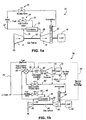
- the invention relates to a simple cycle gas turbine system comprising: a compressor, a turbine component and a load, wherein fuel and compressor discharge bleed air are supplied to a combustor and gaseous products of combustion are introduced into the turbine component and subsequently exhausted to atmosphere; and a compressor discharge bleed air circuit that removes bleed air from the compressor and supplies one portion of the bleed air to the combustor and another portion of the bleed air to an exhaust stack of the turbine component.
- the simple cycle gas turbine system 10 includes a compressor 12, a turbine component 14 and a load (e.g., a generator) 16 arranged on a single rotor or shaft 18.
- a combustor 20 of the gas turbine receives fuel via stream 22 and control valve 24, as well as hot discharge air bled off from the compressor 12 via stream 26. Combustion gases are introduced into the turbine component 14 via stream 28.
- a compressor discharge bleed air circuit is utilized. This circuit causes some of the compressor discharge bleed air to bypass the combustor and directs the bleed air directly to the gas turbine exhaust stack 30 via stream 32 and throttle valve 34, the valve 34 also controlling the amount of bleed air introduced into the combustor 20.
- the gas turbine system 36 includes a compressor 38, a turbine component 40 and a load (e.g., a generator) 42, arranged on a single rotor or shaft 44.
- the combustor 46 receives fuel via stream 48 and fuel control valve 50; and compressor discharge bleed air from the compressor 38 via stream 52. Combustion gases are introduced into the turbine component 40 via stream 54. A predetermined percentage of the compressor discharge bleed air is directed to a flow control/bypass valve 56.
- valve 56 supplies compressor discharge bleed air to an air expander 68 via stream 70, and the air representing the difference between the compressor air discharge pressure and the gas turbine exhaust pressure, is then used to drive a secondary load 72 (e.g., a generator) via shaft 74.
- a secondary load 72 e.g., a generator
- the valve 56 can adjustably divert the compressor discharge bleed air to the gas turbine exhaust stack 58 via stream 60 and flow control throttle valve 62. This is useful as a bypass scheme (bypassing expander 68) to continue plant operation during start-up, shut-down and other events when the expander is not operating.
- valve 56 may supply the compressor discharge bleed air to a pre-heater 64 via stream 66.
- Pre-heater 64 heats the bleed air by heat exchange with turbine exhaust air fed to the pre-heater 64 via stream 76.
- the heated bleed air is then expanded as described above.
- the pre-heater 64 optionally, may be fired using fuel separately introduced via stream 76. Excess air from the expander 68 is introduced into stream 60 via stream 80 and then to the gas turbine exhaust stack 58. Some percentage of this excess air may be allowed to bypass the stack 58 and escape to atmosphere upstream of the stack 58 via stream 81 and valve 82.
- a combined cycle system 84 includes a gas turbine including a compressor 86, a turbine component 88 and a load (e.g., a generator) 90 arranged on a single shaft 92.
- Combustor 94 receives fuel via stream 96 and fuel control valve 98 along with compressor discharge air bled off from the compressor 86 via stream 100.
- the gas turbine exhaust is supplied via stream 102 to a heat recovery steam generator (HRSG) 104 for reheating steam from a steam turbine 106.
- HRSG heat recovery steam generator
- Condensed steam from steam turbine 106 is supplied to the HRSG 104 via stream 108 and the reheated steam is returned to the steam turbine via stream 110.
- Steam turbine 106 drives a second generator 107 via shaft 112.
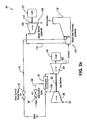
- This combined cycle system 120 includes a gas turbine having a compressor 122, a turbine component 124 and a load (e.g., a generator) 126 arranged on a single shaft 128.
- Combustor 130 receives fuel via stream 132 and fuel control valve 134, along with compressor discharge air bled off from the compressor 122 via stream 136.
- Combustion gases from the combustor 130 are introduced into the turbine 124 via stream 131.
- the gas turbine exhaust is supplied via stream 140 to an HRSG 142 for reheating steam from the steam turbine 142.
- Condensed steam from the steam turbine 142 is supplied to the HRSG 142 via stream 144; and the reheated steam is returned to the steam turbine 142 via stream 146.
- Steam turbine 142 drives a generator.
- a predetermined percentage of the compressor discharge bleed air is directed to a flow control/bypass valve 148 via stream 150.
- Valve 148 supplies the bleed air to the expander 162 via stream 158.
- the bleed air can first be supplied to a pre-heater 156 via stream 158.
- the pre-heater 156 heats the compressor discharge bleed air via heat exchange with gas turbine exhaust in the HRSG via stream 160.
- the pre-heater 156 optionally, may be fired using fuel introduced via stream 170.
- the heated compressor discharge bleed air is then expanded in the air expander 162 and the excess air is used to drive a third load (e.g., a generator) 166 via shaft 168.
- a third load e.g., a generator
- the valve 148 may divert the compressor discharge bleed air to the HRSG 142 via stream 152 and flow control/throttle valve 154, thus bypassing the pre-heater 156 and expander 162.
- air from the expander 162 is dumped into the stream 152 upstream of the HRSG 142, via a stream. It is eventually exhausted to atmosphere through the HRSG stack 172. Some percentage of this air may bypass the HRSG 142 and escape to atmosphere via stream 174 and valve 176.
- compressor discharge bleed air circuits described above are useful under conditions that lead to compressor surge, i.e., low ambient air temperatures; excess flow to the turbine; use of fuels with low heat content, etc.
Landscapes
- Engineering & Computer Science (AREA)
- Chemical & Material Sciences (AREA)
- Combustion & Propulsion (AREA)
- Mechanical Engineering (AREA)
- General Engineering & Computer Science (AREA)
- Physics & Mathematics (AREA)
- Fluid Mechanics (AREA)
- Life Sciences & Earth Sciences (AREA)
- Sustainable Development (AREA)
- Engine Equipment That Uses Special Cycles (AREA)
- Control Of Turbines (AREA)
- Control Of Positive-Displacement Air Blowers (AREA)
Applications Claiming Priority (2)
| Application Number | Priority Date | Filing Date | Title |
|---|---|---|---|
| US659687 | 2000-09-11 | ||
| US09/659,687 US6442941B1 (en) | 2000-09-11 | 2000-09-11 | Compressor discharge bleed air circuit in gas turbine plants and related method |
Publications (3)
| Publication Number | Publication Date |
|---|---|
| EP1186761A2 EP1186761A2 (en) | 2002-03-13 |
| EP1186761A3 EP1186761A3 (en) | 2003-11-05 |
| EP1186761B1 true EP1186761B1 (en) | 2013-03-06 |
Family
ID=24646386
Family Applications (1)
| Application Number | Title | Priority Date | Filing Date |
|---|---|---|---|
| EP01304220A Expired - Lifetime EP1186761B1 (en) | 2000-09-11 | 2001-05-11 | Energy recovery from compressor discharge bleed air in gas turbine plants |
Country Status (5)
| Country | Link |
|---|---|
| US (2) | US6442941B1 (enExample) |
| EP (1) | EP1186761B1 (enExample) |
| JP (1) | JP4754090B2 (enExample) |
| KR (1) | KR100818830B1 (enExample) |
| CZ (1) | CZ200144A3 (enExample) |
Families Citing this family (102)
| Publication number | Priority date | Publication date | Assignee | Title |
|---|---|---|---|---|
| US20020158517A1 (en) * | 2000-11-14 | 2002-10-31 | Rouse Gregory C. | Method and apparatus for turbogenerator anti-surge control |
| JP3702267B2 (ja) * | 2002-11-13 | 2005-10-05 | 三菱重工業株式会社 | 一軸形コンバインドサイクルプラント |
| US6976351B2 (en) * | 2003-04-04 | 2005-12-20 | General Electric Company | Methods and apparatus for monitoring gas turbine combustion dynamics |
| DE10355917A1 (de) | 2003-11-29 | 2005-06-30 | Mtu Aero Engines Gmbh | Gasturbine, insbesondere Flugtriebwerk, und Verfahren zur Erzeugung elektrischer Energie bei einer Gasturbine |
| GB0415376D0 (en) | 2004-07-09 | 2004-08-11 | Rolls Royce Plc | A turbine engine arrangement |
| US7185495B2 (en) * | 2004-09-07 | 2007-03-06 | General Electric Company | System and method for improving thermal efficiency of dry low emissions combustor assemblies |
| US20070151257A1 (en) * | 2006-01-05 | 2007-07-05 | Maier Mark S | Method and apparatus for enabling engine turn down |
| US7784288B2 (en) * | 2006-03-06 | 2010-08-31 | General Electric Company | Methods and systems of variable extraction for compressor protection |
| EP1835131A1 (de) * | 2006-03-15 | 2007-09-19 | Siemens Aktiengesellschaft | Gasturbine für ein thermisches Kraftwerk und Verfahren zum Betreiben einer derartigen Gasturbine |
| US8479523B2 (en) * | 2006-05-26 | 2013-07-09 | General Electric Company | Method for gas turbine operation during under-frequency operation through use of air extraction |
| US7704038B2 (en) * | 2006-11-28 | 2010-04-27 | General Electric Company | Method and apparatus to facilitate reducing losses in turbine engines |
| US7685802B2 (en) * | 2006-12-19 | 2010-03-30 | General Electric Company | Methods and apparatus to facilitate gas turbine fuel control |
| US7861532B2 (en) * | 2007-06-26 | 2011-01-04 | General Electric Company | System and methods for heat recovery steam generators hot purging |
| US8209951B2 (en) * | 2007-08-31 | 2012-07-03 | General Electric Company | Power generation system having an exhaust attemperating device |
| US8388308B2 (en) * | 2007-10-30 | 2013-03-05 | General Electric Company | Asymmetric flow extraction system |
| US7707818B2 (en) * | 2008-02-11 | 2010-05-04 | General Electric Company | Exhaust stacks and power generation systems for increasing gas turbine power output |
| JP4196307B1 (ja) * | 2008-03-06 | 2008-12-17 | 三浦工業株式会社 | 蒸気システム |
| US8522528B2 (en) * | 2008-06-30 | 2013-09-03 | Solar Turbines Inc. | System for diffusing bleed air flow |
| US20100003123A1 (en) * | 2008-07-01 | 2010-01-07 | Smith Craig F | Inlet air heating system for a gas turbine engine |
| KR101032166B1 (ko) * | 2008-09-29 | 2011-05-02 | 이강욱 | 충진이 용이한 쿠션세트. |
| US8117821B2 (en) * | 2009-02-11 | 2012-02-21 | General Electric Company | Optimization of low-BTU fuel-fired combined-cycle power plant by performance heating |
| US20100242489A1 (en) * | 2009-03-31 | 2010-09-30 | Rajarshi Saha | Systems, Methods, and Apparatus for Modifying Power Output and Efficiency of a Combined Cycle Power Plant |
| IT1396514B1 (it) * | 2009-11-27 | 2012-12-14 | Nuovo Pignone Spa | Metodo di controllo di turbina basato su rapporto tra temperatura di scarico e pressione di turbina |
| IT1396515B1 (it) | 2009-11-27 | 2012-12-14 | Nuovo Pignone Spa | Soglia basata su temperatura di scarico per metodo di controllo e turbina |
| IT1396516B1 (it) * | 2009-11-27 | 2012-12-14 | Nuovo Pignone Spa | Metodo di controllo di modo basato su temperatura di scarico per turbina a gas e turbina a gas |
| US20110162386A1 (en) * | 2010-01-04 | 2011-07-07 | Shinoj Vakkayil Chandrabose | Ejector-OBB Scheme for a Gas Turbine |
| US8863492B2 (en) * | 2010-01-19 | 2014-10-21 | Siemens Energy, Inc. | Combined cycle power plant with split compressor |
| US8978380B2 (en) | 2010-08-10 | 2015-03-17 | Dresser-Rand Company | Adiabatic compressed air energy storage process |
| US8726628B2 (en) * | 2010-10-22 | 2014-05-20 | General Electric Company | Combined cycle power plant including a carbon dioxide collection system |
| US8281596B1 (en) | 2011-05-16 | 2012-10-09 | General Electric Company | Combustor assembly for a turbomachine |
| US20120317973A1 (en) * | 2011-06-14 | 2012-12-20 | General Electric Company | Asymmetrical Combined Cycle Power Plant |
| EP2559862B1 (en) * | 2011-08-19 | 2021-11-10 | Ansaldo Energia IP UK Limited | Control of a blow-off valve responsive to a sudden de-loading of a gas turbine |
| US8899975B2 (en) | 2011-11-04 | 2014-12-02 | General Electric Company | Combustor having wake air injection |
| US9267687B2 (en) | 2011-11-04 | 2016-02-23 | General Electric Company | Combustion system having a venturi for reducing wakes in an airflow |
| US9297316B2 (en) | 2011-11-23 | 2016-03-29 | General Electric Company | Method and apparatus for optimizing the operation of a turbine system under flexible loads |
| NL2007917C2 (en) | 2011-12-01 | 2013-06-06 | Draka Comteq Bv | A device for applying electromagnetic microwave radiation in a plasma inside a hollow glass substrate tube, and method for manufacturing an optical preform. |
| WO2013151909A1 (en) * | 2012-04-02 | 2013-10-10 | Kraft Robert J | Compressed air injection system method and apparatus for gas turbine engines |
| US9239007B2 (en) * | 2012-05-31 | 2016-01-19 | General Electric Company | Gas turbine compressor inlet pressurization having a torque converter system |
| US9771864B2 (en) * | 2012-05-31 | 2017-09-26 | General Electric Company | Gas turbine compressor inlet pressurization and flow control system |
| US20130318941A1 (en) * | 2012-05-31 | 2013-12-05 | General Electric Company | Supercharged Combined Cycle System With Air Flow Bypass |
| RU2563445C2 (ru) * | 2012-07-13 | 2015-09-20 | Альстом Текнолоджи Лтд | Способ и устройство для регулирования помпажа газотурбинного двигателя |
| US9027354B2 (en) | 2012-07-30 | 2015-05-12 | General Elecric Company | System and method for recirculating and recovering energy from compressor discharge bleed air |
| US9003762B2 (en) * | 2012-10-02 | 2015-04-14 | General Electric Company | Turbine exhaust plume mitigation system |
| GB201218611D0 (en) * | 2012-10-17 | 2012-11-28 | Tuyere Ltd | Heat engine |
| RU2694600C2 (ru) | 2012-10-26 | 2019-07-16 | ПАУЭРФЭЙЗ ЭлЭлСи | Системы восполнения энергии и системы подогрева газовых турбин, а также способы их изготовления и использования |
| US9938895B2 (en) | 2012-11-20 | 2018-04-10 | Dresser-Rand Company | Dual reheat topping cycle for improved energy efficiency for compressed air energy storage plants with high air storage pressure |
| US9447732B2 (en) | 2012-11-26 | 2016-09-20 | General Electric Company | Gas turbine anti-icing system |
| US9228501B2 (en) * | 2012-12-14 | 2016-01-05 | Solar Turbines Incorporated | Bleed valve override schedule on off-load transients |
| US9611752B2 (en) * | 2013-03-15 | 2017-04-04 | General Electric Company | Compressor start bleed system for a turbine system and method of controlling a compressor start bleed system |
| US9719418B2 (en) | 2013-04-01 | 2017-08-01 | General Electric Company | Turbomachine inlet bleed heating assembly |
| US9739201B2 (en) | 2013-05-08 | 2017-08-22 | General Electric Company | Wake reducing structure for a turbine system and method of reducing wake |
| US9322553B2 (en) | 2013-05-08 | 2016-04-26 | General Electric Company | Wake manipulating structure for a turbine system |
| US9435221B2 (en) | 2013-08-09 | 2016-09-06 | General Electric Company | Turbomachine airfoil positioning |
| EP2896793B1 (en) | 2014-01-21 | 2024-08-28 | Ansaldo Energia Switzerland AG | Method of operating a gas turbine assembly and the gas turbine assembly |
| DE102014211590A1 (de) * | 2014-06-17 | 2015-12-17 | Siemens Aktiengesellschaft | Gasturbinengeneratorkühlung |
| US10472071B2 (en) | 2014-07-09 | 2019-11-12 | United Technologies Corporation | Hybrid compressor bleed air for aircraft use |
| US9890709B2 (en) | 2014-11-03 | 2018-02-13 | General Electric Company | Method and system for gas turbine extraction |
| US10626755B2 (en) | 2015-03-04 | 2020-04-21 | General Electric Company | Systems and methods for turbine system operation in low ambient temperatures |
| US9828887B2 (en) | 2015-03-19 | 2017-11-28 | General Electric Company | Power generation system having compressor creating excess air flow and turbo-expander to increase turbine exhaust gas mass flow |
| US20160273408A1 (en) * | 2015-03-19 | 2016-09-22 | General Electric Company | Power generation system having compressor creating excess air flow and eductor for augmenting same |
| US20160273403A1 (en) * | 2015-03-19 | 2016-09-22 | General Electric Company | Power generation system having compressor creating excess air flow and turbo-expander using same |
| US10024197B2 (en) | 2015-03-19 | 2018-07-17 | General Electric Company | Power generation system having compressor creating excess air flow and turbo-expander using same |
| US20160271560A1 (en) * | 2015-03-19 | 2016-09-22 | General Electric Company | Power generation system having compressor creating excess air flow for scr unit |
| US20160273409A1 (en) * | 2015-03-19 | 2016-09-22 | General Electric Company | Power generation system having compressor creating excess air flow and turbo-expander for supplemental generator |
| US9863284B2 (en) | 2015-03-19 | 2018-01-09 | General Electric Company | Power generation system having compressor creating excess air flow and cooling fluid injection therefor |
| US20160273407A1 (en) * | 2015-03-19 | 2016-09-22 | General Electric Company | Power generation system having compressor creating excess air flow and burner module therefor |
| US9863285B2 (en) | 2015-03-19 | 2018-01-09 | General Electric Company | Power generation system having compressor creating excess gas flow for supplemental gas turbine system |
| US9822670B2 (en) | 2015-03-19 | 2017-11-21 | General Electric Company | Power generation system having compressor creating excess air flow and turbo-expander for cooling inlet air |
| US20160273396A1 (en) * | 2015-03-19 | 2016-09-22 | General Electric Company | Power generation system having compressor creating excess air flow and heat exchanger therefor |
| US10975733B2 (en) * | 2015-04-24 | 2021-04-13 | Nuovo Pignone Srl | Compressor driven by ORC waste heat recovery unit and control method |
| US10030558B2 (en) * | 2015-06-29 | 2018-07-24 | General Electric Company | Power generation system exhaust cooling |
| US10060316B2 (en) * | 2015-06-29 | 2018-08-28 | General Electric Company | Power generation system exhaust cooling |
| US10215070B2 (en) | 2015-06-29 | 2019-02-26 | General Electric Company | Power generation system exhaust cooling |
| RU2605878C1 (ru) * | 2015-08-12 | 2016-12-27 | федеральное государственное бюджетное образовательное учреждение высшего образования "Национальный исследовательский университет "МЭИ" (ФГБОУ ВО "НИУ "МЭИ") | Турбодетандерная система утилизации теплоты циркуляционной воды на конденсационных блоках паровых турбин тепловой электрической станции |
| US10851677B2 (en) | 2015-08-28 | 2020-12-01 | Ingersoll-Rand Industrial U.S., Inc. | Boiler with integrated air compressor |
| US9874143B2 (en) | 2015-12-15 | 2018-01-23 | General Electric Company | System for generating steam and for providing cooled combustion gas to a secondary gas turbine combustor |
| US10584615B2 (en) | 2015-12-15 | 2020-03-10 | General Electric Company | System for generating steam via turbine extraction and compressor extraction including an ejector and static mixer |
| US10072573B2 (en) | 2015-12-15 | 2018-09-11 | General Electric Company | Power plant including an ejector and steam generating system via turbine extraction |
| US10577982B2 (en) | 2015-12-15 | 2020-03-03 | General Electric Company | Power plant with steam generation via turbine extraction and including a gas distribution manifold |
| US9890710B2 (en) | 2015-12-15 | 2018-02-13 | General Electric Company | Power plant with steam generation via combustor gas extraction |
| US10415432B2 (en) | 2015-12-15 | 2019-09-17 | General Electric Company | Power plant with steam generation and fuel heating capabilities |
| US9970354B2 (en) | 2015-12-15 | 2018-05-15 | General Electric Company | Power plant including an ejector and steam generating system via turbine extraction and compressor extraction |
| US9964035B2 (en) | 2015-12-15 | 2018-05-08 | General Electric Company | Power plant including exhaust gas coolant injection system and steam generating system via turbine extraction |
| US10436073B2 (en) | 2015-12-15 | 2019-10-08 | General Electric Company | System for generating steam via turbine extraction and compressor extraction |
| US9976479B2 (en) | 2015-12-15 | 2018-05-22 | General Electric Company | Power plant including a static mixer and steam generating system via turbine extraction and compressor extraction |
| US10415476B2 (en) | 2015-12-15 | 2019-09-17 | General Electric Company | System for generating steam and for providing cooled combustion gas to a secondary gas turbine |
| US10253652B2 (en) | 2015-12-15 | 2019-04-09 | General Electric Company | System and method for controlling gas turbine output via an exhaust damper |
| US10563581B2 (en) | 2016-05-27 | 2020-02-18 | General Electric Company | System and method of compressor inlet temperature control with eductor |
| US10619568B2 (en) | 2016-05-27 | 2020-04-14 | General Elecric Company | System and method of compressor inlet temperature control with mixing chamber |
| US10316759B2 (en) | 2016-05-31 | 2019-06-11 | General Electric Company | Power generation system exhaust cooling |
| US10082090B2 (en) * | 2016-08-25 | 2018-09-25 | General Electric Company | Systems and methods to improve shut-down purge flow in a gas turbine system |
| US10082091B2 (en) * | 2016-08-25 | 2018-09-25 | General Electric Company | Systems and methods to improve shut-down purge flow in a gas turbine system |
| PL421253A1 (pl) | 2017-04-10 | 2018-10-22 | General Electric Company | System wylotowy sprężarki |
| JP7349320B2 (ja) * | 2019-10-25 | 2023-09-22 | 三菱重工業株式会社 | ガスタービン装置及びその製造方法並びにガスタービン装置の運転方法 |
| US12162607B2 (en) * | 2020-11-12 | 2024-12-10 | Hamilton Sundstrand Corporation | Environmental control system for supersonic commercial aircraft |
| WO2023009161A1 (en) * | 2021-07-27 | 2023-02-02 | General Electric Company | Oxy-combustion combined cycle power plants |
| US20230228216A1 (en) * | 2022-01-19 | 2023-07-20 | General Electric Company | Bleed flow assembly for a gas turbine engine |
| US11702981B1 (en) * | 2022-04-20 | 2023-07-18 | Raytheon Technologies Corporation | Turbine engine bleed waste heat recovery |
| US11773778B1 (en) * | 2022-09-23 | 2023-10-03 | Rtx Corporation | Air bottoming cycle air cycle system source |
| US11905963B1 (en) * | 2022-11-21 | 2024-02-20 | Saudi Arabian Oil Company | Compressor startup |
| WO2025004539A1 (ja) * | 2023-06-30 | 2025-01-02 | 三菱パワー株式会社 | ガスタービン発電プラント、及びその運転方法 |
| JP2025161515A (ja) * | 2024-04-12 | 2025-10-24 | 三菱重工業株式会社 | ガスタービン発電プラント、及びその運転方法 |
Family Cites Families (21)
| Publication number | Priority date | Publication date | Assignee | Title |
|---|---|---|---|---|
| US2826038A (en) * | 1953-09-17 | 1958-03-11 | Vickers Electrical Co Ltd | Gas turbine plant with liquid and gaseous fuels |
| BE537620A (enExample) * | 1954-04-27 | |||
| BE547127A (enExample) * | 1955-04-22 | |||
| GB1019203A (en) * | 1964-06-18 | 1966-02-02 | Rolls Royce | Jet nozzle |
| DE1751851B2 (de) * | 1968-08-08 | 1973-12-13 | Motoren- Und Turbinen-Union Muenchen Gmbh, 8000 Muenchen | Gasturbinenanlage |
| US3641766A (en) * | 1969-11-26 | 1972-02-15 | Gen Electric | Gas turbine engine constant speed thrust modulation |
| US3998047A (en) * | 1975-04-18 | 1976-12-21 | The United States Of America As Represented By The United States Energy Research And Development Administration | Method and apparatus for preventing overspeed in a gas turbine |
| GB2049816B (en) * | 1979-05-17 | 1983-01-26 | Curtiss Wright Corp | Gas turbine power plant having an air-cooled pressurized fluidized bed combustor |
| JPS58195711A (ja) * | 1982-05-10 | 1983-11-15 | Hitachi Ltd | トランジシヨンピ−ス冷却装置 |
| JPS6166019A (ja) * | 1984-09-07 | 1986-04-04 | Mitsubishi Heavy Ind Ltd | ガスタ−ビン燃焼器 |
| JPS64326A (en) * | 1987-06-23 | 1989-01-05 | Hitachi Ltd | Nox abating type gas turbine plant |
| JPH04214931A (ja) * | 1990-01-30 | 1992-08-05 | Hitachi Ltd | ガスタービン設備 |
| JPH0666155A (ja) * | 1992-08-19 | 1994-03-08 | Mitsubishi Heavy Ind Ltd | 外部燃焼型ガスタービン複合発電プラント |
| US5488823A (en) * | 1993-05-12 | 1996-02-06 | Gas Research Institute | Turbocharger-based bleed-air driven fuel gas booster system and method |
| JP3368487B2 (ja) * | 1995-04-04 | 2003-01-20 | 日本酸素株式会社 | ガスタービン発電システムにおける吸入空気冷却装置及びその運転方法 |
| US5896740A (en) * | 1996-09-12 | 1999-04-27 | Shouman; Ahmad R. | Dual cycle turbine engine having increased efficiency and heat recovery system for use therein |
| US5896738A (en) * | 1997-04-07 | 1999-04-27 | Siemens Westinghouse Power Corporation | Thermal chemical recuperation method and system for use with gas turbine systems |
| EP0915242B1 (en) * | 1997-11-04 | 2003-09-03 | Hitachi, Ltd. | Gas turbine |
| JP3788071B2 (ja) * | 1997-11-04 | 2006-06-21 | 株式会社日立製作所 | ガスタービン |
| GB2335953A (en) * | 1998-03-30 | 1999-10-06 | Magnox Electric Plc | Air extraction from a power generation turbine |
| JP2000054857A (ja) * | 1998-08-10 | 2000-02-22 | Hitachi Ltd | ガスタービン |
-
2000
- 2000-09-11 US US09/659,687 patent/US6442941B1/en not_active Expired - Lifetime
-
2001
- 2001-01-04 CZ CZ200144A patent/CZ200144A3/cs unknown
- 2001-05-08 KR KR1020010024936A patent/KR100818830B1/ko not_active Expired - Fee Related
- 2001-05-10 JP JP2001139395A patent/JP4754090B2/ja not_active Expired - Fee Related
- 2001-05-11 EP EP01304220A patent/EP1186761B1/en not_active Expired - Lifetime
-
2002
- 2002-05-24 US US10/153,609 patent/US6543234B2/en not_active Expired - Fee Related
Also Published As
| Publication number | Publication date |
|---|---|
| KR100818830B1 (ko) | 2008-04-01 |
| JP4754090B2 (ja) | 2011-08-24 |
| US20020129608A1 (en) | 2002-09-19 |
| EP1186761A2 (en) | 2002-03-13 |
| EP1186761A3 (en) | 2003-11-05 |
| JP2002097970A (ja) | 2002-04-05 |
| KR20020020834A (ko) | 2002-03-16 |
| US6543234B2 (en) | 2003-04-08 |
| CZ200144A3 (cs) | 2002-04-17 |
| US6442941B1 (en) | 2002-09-03 |
Similar Documents
| Publication | Publication Date | Title |
|---|---|---|
| EP1186761B1 (en) | Energy recovery from compressor discharge bleed air in gas turbine plants | |
| EP1905964B1 (en) | Gas turbine engine | |
| EP3183433B1 (en) | Power generation system and method for generating power | |
| US8051654B2 (en) | Reheat gas and exhaust gas regenerator system for a combined cycle power plant | |
| EP0939202B1 (en) | Steam cooled gas turbine system | |
| US6442924B1 (en) | Optimized steam turbine peaking cycles utilizing steam bypass and related process | |
| US6792756B2 (en) | Gas supply control device for a gas storage power plant | |
| EP3354865B1 (en) | Steam turbine preheating system with a steam generator | |
| CN106089341B (zh) | 增强多燃气涡轮联合循环装置中冷蒸汽涡轮启动的方法 | |
| JPH0586898A (ja) | 半開放サイクル動作型天然ガス蒸気タービンシステム | |
| EP3354877B1 (en) | Steam turbine preheating system | |
| CN104981587A (zh) | 联合循环发电厂及用于操作此类联合循环发电厂的方法 | |
| EP1285151B1 (en) | Method and apparatus for power augmentation for gas turbine power cycles | |
| US20100077722A1 (en) | Peak load management by combined cycle power augmentation using peaking cycle exhaust heat recovery | |
| US20070256424A1 (en) | Heat recovery gas turbine in combined brayton cycle power generation | |
| US6161385A (en) | Turbomachine and method of use | |
| US9279365B2 (en) | Power augmentation systems and methods for grid frequency control | |
| WO1997031184A1 (en) | Hydrogen fueled power plant with recuperation | |
| US20170248036A1 (en) | System and method for managing heat recovery steam generator inlet temperature | |
| JP2005344528A (ja) | コンバインドサイクル発電プラントおよびその起動運転方法 | |
| Takano et al. | Design for the 145-MW blast furnace gas firing gas turbine combined cycle plant | |
| EP2325456B1 (en) | Gas turbine cycle with water injection for generating electricity | |
| JP3133034B2 (ja) | コンバインドサイクルプラント | |
| Roberts | Application of the Centaur industrial gas turbine to the central receiver concept for solar electric power | |
| GB2445486A (en) | Gas turbine engine exhaust plume suppression |
Legal Events
| Date | Code | Title | Description |
|---|---|---|---|
| PUAI | Public reference made under article 153(3) epc to a published international application that has entered the european phase |
Free format text: ORIGINAL CODE: 0009012 |
|
| AK | Designated contracting states |
Kind code of ref document: A2 Designated state(s): AT BE CH CY DE DK ES FI FR GB GR IE IT LI LU MC NL PT SE TR |
|
| AX | Request for extension of the european patent |
Free format text: AL;LT;LV;MK;RO;SI |
|
| PUAL | Search report despatched |
Free format text: ORIGINAL CODE: 0009013 |
|
| AK | Designated contracting states |
Kind code of ref document: A3 Designated state(s): AT BE CH CY DE DK ES FI FR GB GR IE IT LI LU MC NL PT SE TR |
|
| AX | Request for extension of the european patent |
Extension state: AL LT LV MK RO SI |
|
| 17P | Request for examination filed |
Effective date: 20040506 |
|
| AKX | Designation fees paid |
Designated state(s): AT BE CH CY DE DK ES FI FR GB GR IE IT LI LU MC NL PT SE TR |
|
| 17Q | First examination report despatched |
Effective date: 20040708 |
|
| 17Q | First examination report despatched |
Effective date: 20040708 |
|
| REG | Reference to a national code |
Ref country code: DE Ref legal event code: R079 Ref document number: 60147724 Country of ref document: DE Free format text: PREVIOUS MAIN CLASS: F02C0009180000 Ipc: F02C0007320000 |
|
| RIC1 | Information provided on ipc code assigned before grant |
Ipc: F04D 27/02 20060101ALI20120420BHEP Ipc: F02C 9/18 20060101ALI20120420BHEP Ipc: F02C 7/32 20060101AFI20120420BHEP |
|
| GRAP | Despatch of communication of intention to grant a patent |
Free format text: ORIGINAL CODE: EPIDOSNIGR1 |
|
| GRAS | Grant fee paid |
Free format text: ORIGINAL CODE: EPIDOSNIGR3 |
|
| GRAA | (expected) grant |
Free format text: ORIGINAL CODE: 0009210 |
|
| AK | Designated contracting states |
Kind code of ref document: B1 Designated state(s): AT BE CH CY DE DK ES FI FR GB GR IE IT LI LU MC NL PT SE TR |
|
| REG | Reference to a national code |
Ref country code: GB Ref legal event code: FG4D |
|
| REG | Reference to a national code |
Ref country code: CH Ref legal event code: EP Ref country code: AT Ref legal event code: REF Ref document number: 599756 Country of ref document: AT Kind code of ref document: T Effective date: 20130315 |
|
| REG | Reference to a national code |
Ref country code: IE Ref legal event code: FG4D |
|
| REG | Reference to a national code |
Ref country code: CH Ref legal event code: NV Representative=s name: SERVOPATENT GMBH, CH |
|
| REG | Reference to a national code |
Ref country code: DE Ref legal event code: R096 Ref document number: 60147724 Country of ref document: DE Effective date: 20130502 |
|
| REG | Reference to a national code |
Ref country code: NL Ref legal event code: T3 |
|
| REG | Reference to a national code |
Ref country code: SE Ref legal event code: TRGR |
|
| REG | Reference to a national code |
Ref country code: AT Ref legal event code: MK05 Ref document number: 599756 Country of ref document: AT Kind code of ref document: T Effective date: 20130306 |
|
| PG25 | Lapsed in a contracting state [announced via postgrant information from national office to epo] |
Ref country code: AT Free format text: LAPSE BECAUSE OF FAILURE TO SUBMIT A TRANSLATION OF THE DESCRIPTION OR TO PAY THE FEE WITHIN THE PRESCRIBED TIME-LIMIT Effective date: 20130306 Ref country code: ES Free format text: LAPSE BECAUSE OF FAILURE TO SUBMIT A TRANSLATION OF THE DESCRIPTION OR TO PAY THE FEE WITHIN THE PRESCRIBED TIME-LIMIT Effective date: 20130617 |
|
| PGFP | Annual fee paid to national office [announced via postgrant information from national office to epo] |
Ref country code: DE Payment date: 20130418 Year of fee payment: 13 Ref country code: GB Payment date: 20130528 Year of fee payment: 13 Ref country code: CH Payment date: 20130530 Year of fee payment: 13 |
|
| PG25 | Lapsed in a contracting state [announced via postgrant information from national office to epo] |
Ref country code: GR Free format text: LAPSE BECAUSE OF FAILURE TO SUBMIT A TRANSLATION OF THE DESCRIPTION OR TO PAY THE FEE WITHIN THE PRESCRIBED TIME-LIMIT Effective date: 20130607 Ref country code: FI Free format text: LAPSE BECAUSE OF FAILURE TO SUBMIT A TRANSLATION OF THE DESCRIPTION OR TO PAY THE FEE WITHIN THE PRESCRIBED TIME-LIMIT Effective date: 20130306 |
|
| PGFP | Annual fee paid to national office [announced via postgrant information from national office to epo] |
Ref country code: IT Payment date: 20130523 Year of fee payment: 13 Ref country code: FR Payment date: 20130522 Year of fee payment: 13 Ref country code: NL Payment date: 20130526 Year of fee payment: 13 |
|
| PG25 | Lapsed in a contracting state [announced via postgrant information from national office to epo] |
Ref country code: BE Free format text: LAPSE BECAUSE OF FAILURE TO SUBMIT A TRANSLATION OF THE DESCRIPTION OR TO PAY THE FEE WITHIN THE PRESCRIBED TIME-LIMIT Effective date: 20130306 |
|
| PG25 | Lapsed in a contracting state [announced via postgrant information from national office to epo] |
Ref country code: PT Free format text: LAPSE BECAUSE OF FAILURE TO SUBMIT A TRANSLATION OF THE DESCRIPTION OR TO PAY THE FEE WITHIN THE PRESCRIBED TIME-LIMIT Effective date: 20130708 |
|
| PG25 | Lapsed in a contracting state [announced via postgrant information from national office to epo] |
Ref country code: CY Free format text: LAPSE BECAUSE OF FAILURE TO SUBMIT A TRANSLATION OF THE DESCRIPTION OR TO PAY THE FEE WITHIN THE PRESCRIBED TIME-LIMIT Effective date: 20130306 |
|
| PG25 | Lapsed in a contracting state [announced via postgrant information from national office to epo] |
Ref country code: MC Free format text: LAPSE BECAUSE OF FAILURE TO SUBMIT A TRANSLATION OF THE DESCRIPTION OR TO PAY THE FEE WITHIN THE PRESCRIBED TIME-LIMIT Effective date: 20130306 |
|
| PLBE | No opposition filed within time limit |
Free format text: ORIGINAL CODE: 0009261 |
|
| STAA | Information on the status of an ep patent application or granted ep patent |
Free format text: STATUS: NO OPPOSITION FILED WITHIN TIME LIMIT |
|
| PG25 | Lapsed in a contracting state [announced via postgrant information from national office to epo] |
Ref country code: DK Free format text: LAPSE BECAUSE OF FAILURE TO SUBMIT A TRANSLATION OF THE DESCRIPTION OR TO PAY THE FEE WITHIN THE PRESCRIBED TIME-LIMIT Effective date: 20130306 |
|
| 26N | No opposition filed |
Effective date: 20131209 |
|
| REG | Reference to a national code |
Ref country code: IE Ref legal event code: MM4A |
|
| REG | Reference to a national code |
Ref country code: DE Ref legal event code: R097 Ref document number: 60147724 Country of ref document: DE Effective date: 20131209 |
|
| PG25 | Lapsed in a contracting state [announced via postgrant information from national office to epo] |
Ref country code: IE Free format text: LAPSE BECAUSE OF NON-PAYMENT OF DUE FEES Effective date: 20130511 |
|
| PGFP | Annual fee paid to national office [announced via postgrant information from national office to epo] |
Ref country code: SE Payment date: 20130530 Year of fee payment: 13 |
|
| REG | Reference to a national code |
Ref country code: DE Ref legal event code: R119 Ref document number: 60147724 Country of ref document: DE |
|
| REG | Reference to a national code |
Ref country code: NL Ref legal event code: V1 Effective date: 20141201 |
|
| REG | Reference to a national code |
Ref country code: CH Ref legal event code: PL |
|
| GBPC | Gb: european patent ceased through non-payment of renewal fee |
Effective date: 20140511 |
|
| PG25 | Lapsed in a contracting state [announced via postgrant information from national office to epo] |
Ref country code: SE Free format text: LAPSE BECAUSE OF NON-PAYMENT OF DUE FEES Effective date: 20140512 Ref country code: LI Free format text: LAPSE BECAUSE OF NON-PAYMENT OF DUE FEES Effective date: 20140531 Ref country code: CH Free format text: LAPSE BECAUSE OF NON-PAYMENT OF DUE FEES Effective date: 20140531 |
|
| REG | Reference to a national code |
Ref country code: SE Ref legal event code: EUG |
|
| REG | Reference to a national code |
Ref country code: DE Ref legal event code: R119 Ref document number: 60147724 Country of ref document: DE Effective date: 20141202 |
|
| PG25 | Lapsed in a contracting state [announced via postgrant information from national office to epo] |
Ref country code: NL Free format text: LAPSE BECAUSE OF NON-PAYMENT OF DUE FEES Effective date: 20141201 |
|
| REG | Reference to a national code |
Ref country code: FR Ref legal event code: ST Effective date: 20150130 |
|
| PG25 | Lapsed in a contracting state [announced via postgrant information from national office to epo] |
Ref country code: IT Free format text: LAPSE BECAUSE OF NON-PAYMENT OF DUE FEES Effective date: 20140511 Ref country code: DE Free format text: LAPSE BECAUSE OF NON-PAYMENT OF DUE FEES Effective date: 20141202 |
|
| PG25 | Lapsed in a contracting state [announced via postgrant information from national office to epo] |
Ref country code: FR Free format text: LAPSE BECAUSE OF NON-PAYMENT OF DUE FEES Effective date: 20140602 Ref country code: GB Free format text: LAPSE BECAUSE OF NON-PAYMENT OF DUE FEES Effective date: 20140511 |
|
| PG25 | Lapsed in a contracting state [announced via postgrant information from national office to epo] |
Ref country code: TR Free format text: LAPSE BECAUSE OF FAILURE TO SUBMIT A TRANSLATION OF THE DESCRIPTION OR TO PAY THE FEE WITHIN THE PRESCRIBED TIME-LIMIT Effective date: 20130306 |
|
| PG25 | Lapsed in a contracting state [announced via postgrant information from national office to epo] |
Ref country code: LU Free format text: LAPSE BECAUSE OF NON-PAYMENT OF DUE FEES Effective date: 20130511 |