EP1186532A2 - Drehmomentbegrenzungseinrichtung mit zwei Bremsen - Google Patents
Drehmomentbegrenzungseinrichtung mit zwei Bremsen Download PDFInfo
- Publication number
- EP1186532A2 EP1186532A2 EP01307624A EP01307624A EP1186532A2 EP 1186532 A2 EP1186532 A2 EP 1186532A2 EP 01307624 A EP01307624 A EP 01307624A EP 01307624 A EP01307624 A EP 01307624A EP 1186532 A2 EP1186532 A2 EP 1186532A2
- Authority
- EP
- European Patent Office
- Prior art keywords
- brake
- speed
- drive shaft
- trigger
- increasing gear
- Prior art date
- Legal status (The legal status is an assumption and is not a legal conclusion. Google has not performed a legal analysis and makes no representation as to the accuracy of the status listed.)
- Granted
Links
Images


Classifications
-
- B—PERFORMING OPERATIONS; TRANSPORTING
- B64—AIRCRAFT; AVIATION; COSMONAUTICS
- B64D—EQUIPMENT FOR FITTING IN OR TO AIRCRAFT; FLIGHT SUITS; PARACHUTES; ARRANGEMENTS OR MOUNTING OF POWER PLANTS OR PROPULSION TRANSMISSIONS IN AIRCRAFT
- B64D45/00—Aircraft indicators or protectors not otherwise provided for
- B64D45/0005—Devices specially adapted to indicate the position of a movable element of the aircraft, e.g. landing gear
-
- B—PERFORMING OPERATIONS; TRANSPORTING
- B64—AIRCRAFT; AVIATION; COSMONAUTICS
- B64C—AEROPLANES; HELICOPTERS
- B64C13/00—Control systems or transmitting systems for actuating flying-control surfaces, lift-increasing flaps, air brakes, or spoilers
- B64C13/24—Transmitting means
- B64C13/26—Transmitting means without power amplification or where power amplification is irrelevant
- B64C13/28—Transmitting means without power amplification or where power amplification is irrelevant mechanical
- B64C13/34—Transmitting means without power amplification or where power amplification is irrelevant mechanical using toothed gearing
-
- B—PERFORMING OPERATIONS; TRANSPORTING
- B64—AIRCRAFT; AVIATION; COSMONAUTICS
- B64D—EQUIPMENT FOR FITTING IN OR TO AIRCRAFT; FLIGHT SUITS; PARACHUTES; ARRANGEMENTS OR MOUNTING OF POWER PLANTS OR PROPULSION TRANSMISSIONS IN AIRCRAFT
- B64D45/00—Aircraft indicators or protectors not otherwise provided for
- B64D45/0005—Devices specially adapted to indicate the position of a movable element of the aircraft, e.g. landing gear
- B64D2045/001—Devices specially adapted to indicate the position of a movable element of the aircraft, e.g. landing gear for indicating symmetry of flaps deflection
-
- Y—GENERAL TAGGING OF NEW TECHNOLOGICAL DEVELOPMENTS; GENERAL TAGGING OF CROSS-SECTIONAL TECHNOLOGIES SPANNING OVER SEVERAL SECTIONS OF THE IPC; TECHNICAL SUBJECTS COVERED BY FORMER USPC CROSS-REFERENCE ART COLLECTIONS [XRACs] AND DIGESTS
- Y02—TECHNOLOGIES OR APPLICATIONS FOR MITIGATION OR ADAPTATION AGAINST CLIMATE CHANGE
- Y02T—CLIMATE CHANGE MITIGATION TECHNOLOGIES RELATED TO TRANSPORTATION
- Y02T50/00—Aeronautics or air transport
- Y02T50/40—Weight reduction
Definitions
- This invention relates to a device and a method for reducing asymmetry in the wings of an aircraft. More particularly, this invention relates to reducing asymmetry in the wings of an aircraft by preventing an aircraft's flap/slat actuation system from acting in an unplanned and abnormal fashion.
- the lifting force produced by an aircraft's wings may be calculated by the formula (1 ⁇ 2 ⁇ V 2 )x(coefficient of lift)x(wing area), where ⁇ is the density of the air and V is the velocity of the aircraft.
- the aircraft's velocity (typically between 400-600 mile per hour) is generally constant.
- the aircraft's altitude (typically between 25,000 and 35,000 feet) is also generally constant.
- the density of the air during cruising conditions is also generally constant because air density is directly related to the altitude at which the air is measured. -- i.e., as the altitude increases the density of the air decreases and as the altitude decreases the density of the air increases--.
- the aircraft's velocity is the component that has the greatest impact on the lifting force produced during cruising conditions.
- auxiliary devices are added to the leading and trailing edges of the wings to increase the wing's effective camber and area. From the formula described above, increasing the wing's effective camber and area coupled with the increased air density compensates for the lower velocities and allows for a lift to be produced substantially similar to those developed during cruising conditions.
- the high-lift devices on the leading edge of the aircraft's wing are usually called slats and those added to the trailing edges of the wing are usually called flaps.
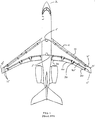
- FIG. 1 shows one embodiment of aircraft 2 which includes Power Drive Unit (PDU) 5, slat 10, wing tip brake 15, flap 20, drive shaft line 25, local actuator 30, and wing 35.
- PDU Power Drive Unit
- Each slat 10 and flap 20 may be installed on the aircraft's airframe at an appropriate point on the wing. Slat 10 and flap 20 are driven by local actuator 30 and by drive shaft line 25. Drive shaft line 25 may be routed down the leading and trailing edges of wing 35. PDU 5 may provide power to local actuator 30 and drive shaft line 25.
- each Torque limiter may sense the torque that is being transmitted to its associated local actuator. If the torque limiter senses excessive torque, then it may cause wing tip brake 15 to be applied and lock down drive shaft line 25.
- Each actuator and torque limiter is preferably connected to one of a plurality of drive shaft lines.
- aircraft with high lift systems typically have asymmetry detection devices (not shown in FIG. 1), which compare the position of the slats and flaps on each wing. If there are differences exceeding a preset allowance, the asymmetry detection device may immediately apply wingtip brake 15 that may lock slat 10 and flap 20 on each wing 35.
- wingtip brake is large and heavy.
- a further disadvantage of the wingtip brake is that the drive shaft line that connects the individual slats and flaps to the wingtip brake might actually be interrupted at several points. For example, due to an engine burst, the drive shaft line might be severed at several points, thus leaving some parts of the drive shaft line not coupled to any brake.
- the present invention addresses these shortcomings.
- an apparatus including a two-brake torque limiting device used to fix the position of one or more flaps or slats on an airplane wing.
- the two-brake torque limiting device preferably includes a speed-increasing gear, a trigger brake, and a lock down brake.
- the speed-increasing gear is preferably coupled to a drive shaft line.
- the speed-increasing gear rotates at a rotational speed proportionally related to and faster than a rotational speed of the drive line shaft.
- the trigger brake is preferably coupled to the speed-increasing gear.
- the trigger brake may apply a braking force to the speed-increasing gear when a control signal is received.
- the lock down brake is preferably coupled to the speed-increasing gear.
- the lock down may apply a braking force to the drive line shaft.
- the braking force may be based upon the rotational motion of the speed-increasing gear, the drive shaft line, and/or a combination of the rotational motion of the speed-increasing gear and the rotational motion of the drive shaft line.
- An apparatus includes a two-brake torque limiting device.
- the two-brake torque limiting device may preferably be used fix the position of one or more flaps and/or slats on an airplane wing during unplanned or abnormal conditions.
- the two-brake torque limiting device may include a trigger brake, a lock down brake, and a speed-increasing device.
- the trigger brake may receive an input from a flap/slat asymmetry detection device.
- the asymmetry detection device compares the respective positions of the flaps and slats on each wing of the aircraft.
- the flap/slat asymmetry detection device may cause the trigger brake to send an input braking force to the lock down brake.
- the lock down brake may apply a braking force to halt the rotation of a flap/slat actuator's drive shaft line.
- the lock down brake may sense the torque on an actuator associated with an individual flap or slat and may apply a braking force to halt a rotation of the actuator's drive shaft line if the torque on the actuator becomes excessive.
- the lock down brake may also receive an input braking force from the trigger brake. When such an input braking force is received, the lock down brake may apply the braking force to halt the rotation of the actuator's drive shaft line.
- the lock down brake and the trigger brake may be connected by a speed-increasing device.
- the speed-increasing device may be used to transmit an input braking force from the trigger brake to the lock down brake using less torque than would be required if no speed-increasing device was used. To allow for the use of less torque, the speed-increasing device may be used to increase the rotational speed of the trigger brake as seen by the drive shaft line.
- a smaller trigger brake may be used.
- the advantage of using a smaller trigger brake is that the size and weight of the trigger brake are reduced. Reducing the size and weight of the trigger brake may allow for the use of one or more such devices.
- the reaction time of the trigger brake may be enhanced.
- the trigger brake may use an electromagnet to generate the input braking force.
- the reaction time of an electromagnet is determined by its size and coil turns. Smaller electromagnets and their respective turns per coil have faster reaction times than larger electromagnets because the time it takes for the magnetic flux to build up and break down in a small electromagnet is shorter than in a larger electromagnet. Smaller electromagnets also handle less torque than larger electromagnets.
- the trigger brake needs to produce only a small braking force --i.e., torque -- to cause the lock down brake to halt a rotation of the drive shaft line--. Therefore, a relatively small electromagnet may be used to enhance the reaction time of the trigger brake while providing an appropriate braking force to the lock down section.
- FIG. 2 is a cross-sectional view of a schematic diagram of one embodiment of apparatus 50 according to the invention. As shown in this view, apparatus 50 includes trigger brake 100, lock down brake 200, and speed increasing device 300.
- Trigger brake 100 may include electromagnetic failsafe brake 110 and output shaft 120.
- Lock down brake 200 may include input shaft 210, spline 220, output shaft 230, input hub 240, output hub 250, brake hub 260, brake disks 270, compression spring 280, and cushion spring 290.
- Speed-increasing device 300 may include idler gears 310.
- lock down brake 100 may function as follows.
- Input shaft 210 and output shaft 230 are preferably each coupled to spline 220.
- torque develops between input shaft 210 and output shaft 230.
- the torque may also be transferred through spline 220 to input hub 240.
- the torque may then be transferred from input hub 240 to output hub 250.
- Input hub 240 and output hub 250 may, for example, by implemented in a roller ramp arrangement.
- the torque may then be transferred from output hub 250 to brake hub 260.
- Compression spring 280 may hold input hub 240, output hub 250, and brake hub 260 closed until a preset torque level is reached. The size and the spring constant of compression spring 280 may determine the preset torque level. Once the preset torque level is reached, compression spring 280 may begin to compress. As compression spring 280 compresses, brake disks 270 may engage and halt the rotation of input shaft 210 and output shaft 230. To prevent input shaft 210 and output shaft 230 from immediately seizing when brake disk 270 is applied, cushion spring 290 may be used to provide a normal force against brake disks 270 to allow for a "soft stop.”
- Trigger brake 100 may function as follows. Electromagnetic failsafe brake 110 may be driven by output shaft 120. Output shaft 120 may be driven by speed-increasing device 300. Speed-increasing device 300 may use idler gears 310 to increase the speed of output shaft 120 and amplify the braking force transmitted to the lock down brake from the trigger brake.
- an asymmetry detection device may send a control signal to trigger brake 100.
- electromagnetic failsafe brake 110 may deenergize and apply a braking force through speed increasing gears 310 to input hub 240. The torque may then be transferred through the lock down brake as described in detail above.
- FIG. 3 shows a flow chart 400 of the operation of an apparatus according to the invention.
- Box 410 shows using an asymmetry detection device to detect asymmetries in the flaps and slats on the wings of an aircraft and to send a control signal to a trigger brake.
- Box 420 shows using the trigger brake to send a braking force to a speed-increasing gear when the control signal from the asymmetry detection device is received.
- Box 430 shows using a speed-increasing gear to amplify the braking force from the trigger brake and to transfer the amplified braking force to a lock down brake.
- Box 440 shows using the lock down brake to halt the rotation of a drive shaft line.
Applications Claiming Priority (10)
| Application Number | Priority Date | Filing Date | Title |
|---|---|---|---|
| US23143900P | 2000-09-08 | 2000-09-08 | |
| US231439P | 2000-09-08 | ||
| US23239600P | 2000-09-14 | 2000-09-14 | |
| US232396P | 2000-09-14 | ||
| US23411000P | 2000-09-21 | 2000-09-21 | |
| US234110P | 2000-09-21 | ||
| US23463800P | 2000-09-22 | 2000-09-22 | |
| US234638P | 2000-09-22 | ||
| US943654 | 2001-08-31 | ||
| US09/943,654 US6659398B2 (en) | 2000-09-08 | 2001-08-31 | Two-brake torque limiting device |
Publications (3)
| Publication Number | Publication Date |
|---|---|
| EP1186532A2 true EP1186532A2 (de) | 2002-03-13 |
| EP1186532A3 EP1186532A3 (de) | 2003-03-26 |
| EP1186532B1 EP1186532B1 (de) | 2005-05-04 |
Family
ID=27539981
Family Applications (1)
| Application Number | Title | Priority Date | Filing Date |
|---|---|---|---|
| EP01307624A Expired - Lifetime EP1186532B1 (de) | 2000-09-08 | 2001-09-07 | Drehmomentbegrenzungseinrichtung mit zwei Bremsen |
Country Status (4)
| Country | Link |
|---|---|
| US (1) | US6659398B2 (de) |
| EP (1) | EP1186532B1 (de) |
| AT (1) | ATE294730T1 (de) |
| DE (1) | DE60110513D1 (de) |
Cited By (2)
| Publication number | Priority date | Publication date | Assignee | Title |
|---|---|---|---|---|
| EP1524431A1 (de) | 2003-10-16 | 2005-04-20 | Natenco Natural Energy Corporation GmbH | Rotorblatt einer Windenergieanlage mit Hinterkanteklappen |
| DE102005011118B4 (de) * | 2004-03-15 | 2008-04-17 | Liebherr-Aerospace Lindenberg Gmbh | Bremsvorrichtung für ein Hochauftriebssystem eines Flugzeuges und Flugzeug mit einer derartigen Vorrichtung |
Families Citing this family (16)
| Publication number | Priority date | Publication date | Assignee | Title |
|---|---|---|---|---|
| JP4638237B2 (ja) * | 2002-11-04 | 2011-02-23 | ホワイト・ハイドローリックス、インコーポレイテッド | 小型一体型ブレーキ・システム |
| US6672540B1 (en) | 2002-12-03 | 2004-01-06 | Rockwell Collins, Inc. | Actuator for aircraft stabilizers with a failure responsive lock control mechanism |
| US7114601B2 (en) * | 2003-04-14 | 2006-10-03 | Curtiss-Wright Controls, Inc. | Torque transfer limiting arrangement for a rotational drive shaft |
| US6824099B1 (en) * | 2003-07-10 | 2004-11-30 | The Boeing Company | Brake systems for aircraft wing flaps and other control surfaces |
| US7743893B2 (en) * | 2005-05-03 | 2010-06-29 | White Drive Products, Inc. | Compact integrated brake system |
| GB0806104D0 (en) * | 2008-04-04 | 2008-05-14 | Goodrich Actuation Systems Ltd | Torque limiter with brake |
| US8393442B2 (en) * | 2008-08-14 | 2013-03-12 | Hamilton Sundstrand Corporation | High gain asymmetry brake |
| FR3008457B1 (fr) * | 2013-07-15 | 2015-07-24 | Eurocopter France | Mecanisme d'accouplement entre un organe de commandes de vol manuelles et un verin de "trim" equipant un aeronef |
| EP3018384A1 (de) * | 2014-11-06 | 2016-05-11 | Goodrich Actuation Systems SAS | Drehantrieb zur Steuerung einer Flugsteuerfläche |
| US9416832B1 (en) | 2015-02-02 | 2016-08-16 | The Boeing Company | Half system torque brakes |
| EP3133017B1 (de) * | 2015-08-18 | 2018-07-04 | Goodrich Actuation Systems Limited | Überwachung von komponentenasymmetrie |
| US10934017B2 (en) * | 2017-09-25 | 2021-03-02 | Hamilton Sunstrand Corporation | Prognostic health monitoring for use with an aircraft |
| US10359089B1 (en) | 2018-01-24 | 2019-07-23 | Hamilton Sundstrand Corporation | Proportional control brake |
| US11015665B2 (en) | 2018-01-24 | 2021-05-25 | Hamilton Sunstrand Corporation | Proportional control brake |
| US10801594B2 (en) * | 2018-05-30 | 2020-10-13 | The Boeing Company | Screw actuator, aircraft comprising a screw actuator, and method of lifting a load |
| US11383822B2 (en) * | 2020-05-20 | 2022-07-12 | The Boeing Company | Distributed active brakes for aircraft high-lift devices |
Family Cites Families (21)
| Publication number | Priority date | Publication date | Assignee | Title |
|---|---|---|---|---|
| US3596740A (en) * | 1970-01-27 | 1971-08-03 | Trw Inc | Torque limiter |
| US4459867A (en) | 1981-12-28 | 1984-07-17 | Sundstrand Corporation | Resettable force limiting device |
| US4441675A (en) * | 1982-06-25 | 1984-04-10 | Mcdonnell Douglas Corporation | High lift surface actuation system |
| EP0146281B1 (de) * | 1983-12-20 | 1987-07-22 | LUCAS INDUSTRIES public limited company | Bremsvorrichtung für ein Drehantriebssystem |
| DE3530865A1 (de) | 1985-08-29 | 1987-03-12 | Messerschmitt Boelkow Blohm | Antriebs- und fuehrungsvorrichtung fuer ein an einem flugzeugtragfluegel angeordnetes klappensystem |
| US4663985A (en) * | 1986-03-07 | 1987-05-12 | Sundstrand Corporation | Shaft relative speed limiting system |
| GB8714495D0 (en) * | 1987-06-20 | 1987-08-19 | Lucas Ind Plc | Torque limiting system |
| US5141084A (en) * | 1990-09-28 | 1992-08-25 | Sundstrand Corporation | Brake stop |
| US5172797A (en) | 1992-01-24 | 1992-12-22 | Eaton Corporation | Motor vehicle inertia and hill holding braking mechanism |
| US5484043A (en) * | 1993-04-28 | 1996-01-16 | Sundstrand Corporation | Speed responsive brake device |
| US5582390A (en) | 1994-11-17 | 1996-12-10 | Sundstrand Corporation | Drive apparatus with primary and secondary no-back features |
| US5680124A (en) * | 1995-05-15 | 1997-10-21 | The Boeing Company | Skew and loss detection system for adjacent high lift devices |
| US5686907A (en) * | 1995-05-15 | 1997-11-11 | The Boeing Company | Skew and loss detection system for individual high lift devices |
| US5743490A (en) | 1996-02-16 | 1998-04-28 | Sundstrand Corporation | Flap/slat actuation system for an aircraft |
| US6196361B1 (en) * | 1996-02-16 | 2001-03-06 | Sundstrand Corporation | Compact electric asymmetry brake |
| US6231012B1 (en) * | 1996-05-15 | 2001-05-15 | Michael J. Cacciola | No-back/offset gear box |
| GB9707984D0 (en) | 1997-04-21 | 1997-06-11 | Dowty Boulton Paul Ltd | Variable torque limiting device |
| DE19724117A1 (de) * | 1997-06-09 | 1998-12-10 | Zf Luftfahrttechnik Gmbh | Bremse für einen Auftriebsklappenverstellmechanismus |
| US6299108B1 (en) * | 1997-12-12 | 2001-10-09 | Jeffrey V. Lindstrom | Method and apparatus for detecting skew and asymmetry of an airplane flap |
| US6366844B1 (en) * | 1997-12-16 | 2002-04-02 | Continental Teves Ag & Co., Ohg | Method and device for limiting transversal acceleration in a motor vehicle |
| US6419606B1 (en) * | 2000-08-17 | 2002-07-16 | Eaton Corporation | Aircraft control surface drive apparatus |
-
2001
- 2001-08-31 US US09/943,654 patent/US6659398B2/en not_active Expired - Fee Related
- 2001-09-07 EP EP01307624A patent/EP1186532B1/de not_active Expired - Lifetime
- 2001-09-07 DE DE60110513T patent/DE60110513D1/de not_active Expired - Lifetime
- 2001-09-07 AT AT01307624T patent/ATE294730T1/de not_active IP Right Cessation
Non-Patent Citations (1)
| Title |
|---|
| None |
Cited By (2)
| Publication number | Priority date | Publication date | Assignee | Title |
|---|---|---|---|---|
| EP1524431A1 (de) | 2003-10-16 | 2005-04-20 | Natenco Natural Energy Corporation GmbH | Rotorblatt einer Windenergieanlage mit Hinterkanteklappen |
| DE102005011118B4 (de) * | 2004-03-15 | 2008-04-17 | Liebherr-Aerospace Lindenberg Gmbh | Bremsvorrichtung für ein Hochauftriebssystem eines Flugzeuges und Flugzeug mit einer derartigen Vorrichtung |
Also Published As
| Publication number | Publication date |
|---|---|
| US6659398B2 (en) | 2003-12-09 |
| EP1186532A3 (de) | 2003-03-26 |
| EP1186532B1 (de) | 2005-05-04 |
| DE60110513D1 (de) | 2005-06-09 |
| US20020030138A1 (en) | 2002-03-14 |
| ATE294730T1 (de) | 2005-05-15 |
Similar Documents
| Publication | Publication Date | Title |
|---|---|---|
| US6659398B2 (en) | Two-brake torque limiting device | |
| US5743490A (en) | Flap/slat actuation system for an aircraft | |
| US6824099B1 (en) | Brake systems for aircraft wing flaps and other control surfaces | |
| US7546975B2 (en) | Tandem rotor wing rotational position control system | |
| CN115230942A (zh) | 具有用于载荷减缓的可移动翼梢装置的飞行器机翼 | |
| US7281900B2 (en) | Cascade rotor blade for low noise | |
| US20150360769A1 (en) | High lift system for an aircraft, aircraft having a wing and a high lift system and method for moving a high lift surface relative to the wing of an aircraft | |
| RU2415776C2 (ru) | Способ и устройство обеспечения автоматического снижения нагрузки на систему поверхностей, создающих большую подъемную силу, в частности на систему посадочных закрылков летательного аппарата | |
| US6643568B2 (en) | System for automatically controlling lift-augmentation devices of an aircraft during take-off | |
| EP3875323B1 (de) | Systeme und verfahren zum antiblockierbremsen eines flugzeugs | |
| CN111372852A (zh) | 用于致动高升力飞行控制表面的系统和方法 | |
| US8373376B2 (en) | Drive system and method for activating the same | |
| US5230486A (en) | Underwing compression vortex attenuation device | |
| US11383822B2 (en) | Distributed active brakes for aircraft high-lift devices | |
| EP3489135B1 (de) | Steuerung von mehreren flugsteuerungsflächensystemen unter verwendung einer einzigen kraftantriebseinheit | |
| CN114620011A (zh) | 飞行器制动器温度控制系统 | |
| GB2583500A (en) | Aircraft wing with a moveable wing tip | |
| US20240158071A1 (en) | Aircraft wing | |
| EP4112453A1 (de) | Verfahren und vorrichtung zur durchführung von gesundheitsüberwachung während des grundbetriebs | |
| EP4011722A1 (de) | Flugzeugbremstemperaturregelsystem | |
| Martin | The Adverse Aerodynamic Effects of Inflight Icing on Airplane Operation | |
| SHEETS et al. | Reverse-Thrust Propellers as Landing Brakes | |
| Malaek et al. | Thrust reverser modulation—a tool to command landing ground run | |
| GB2573105A (en) | Apparatus, aircraft comprising an apparatus and method of performing a descent in an aircraft | |
| SHARMA | Optimal helicopter operation from a clear heliport in the event of one engine failure(Ph. D. Thesis) |
Legal Events
| Date | Code | Title | Description |
|---|---|---|---|
| PUAI | Public reference made under article 153(3) epc to a published international application that has entered the european phase |
Free format text: ORIGINAL CODE: 0009012 |
|
| AK | Designated contracting states |
Kind code of ref document: A2 Designated state(s): AT BE CH CY DE DK ES FI FR GB GR IE IT LI LU MC NL PT SE TR |
|
| AX | Request for extension of the european patent |
Free format text: AL;LT;LV;MK;RO;SI |
|
| PUAL | Search report despatched |
Free format text: ORIGINAL CODE: 0009013 |
|
| AK | Designated contracting states |
Designated state(s): AT BE CH CY DE DK ES FI FR GB GR IE IT LI LU MC NL PT SE TR Kind code of ref document: A3 Designated state(s): AT BE CH CY DE DK ES FI FR GB GR IE IT LI LU MC NL PT SE TR |
|
| AX | Request for extension of the european patent |
Extension state: AL LT LV MK RO SI |
|
| RIC1 | Information provided on ipc code assigned before grant |
Ipc: 7F 16D 67/02 B Ipc: 7F 16H 35/10 B Ipc: 7B 64C 13/28 A |
|
| RAP1 | Party data changed (applicant data changed or rights of an application transferred) |
Owner name: SERVEN, MARK R. |
|
| RAP1 | Party data changed (applicant data changed or rights of an application transferred) |
Owner name: SMITHS AEROSPACE, INC. |
|
| 17P | Request for examination filed |
Effective date: 20030924 |
|
| AKX | Designation fees paid |
Designated state(s): AT BE CH CY DE DK ES FI FR GB GR IE IT LI LU MC NL PT SE TR |
|
| 17Q | First examination report despatched |
Effective date: 20040112 |
|
| GRAP | Despatch of communication of intention to grant a patent |
Free format text: ORIGINAL CODE: EPIDOSNIGR1 |
|
| GRAS | Grant fee paid |
Free format text: ORIGINAL CODE: EPIDOSNIGR3 |
|
| GRAA | (expected) grant |
Free format text: ORIGINAL CODE: 0009210 |
|
| AK | Designated contracting states |
Kind code of ref document: B1 Designated state(s): AT BE CH CY DE DK ES FI FR GB GR IE IT LI LU MC NL PT SE TR |
|
| PG25 | Lapsed in a contracting state [announced via postgrant information from national office to epo] |
Ref country code: IT Free format text: LAPSE BECAUSE OF FAILURE TO SUBMIT A TRANSLATION OF THE DESCRIPTION OR TO PAY THE FEE WITHIN THE PRE;WARNING: LAPSES OF ITALIAN PATENTS WITH EFFECTIVE DATE BEFORE 2007 MAY HAVE OCCURRED AT ANY TIME BEFORE 2007. THE CORRECT EFFECTIVE DATE MAY BE DIFFERENT FROM THE ONE RECORDED.SCRIBED TIME-LIMIT Effective date: 20050504 Ref country code: LI Free format text: LAPSE BECAUSE OF FAILURE TO SUBMIT A TRANSLATION OF THE DESCRIPTION OR TO PAY THE FEE WITHIN THE PRESCRIBED TIME-LIMIT Effective date: 20050504 Ref country code: CH Free format text: LAPSE BECAUSE OF FAILURE TO SUBMIT A TRANSLATION OF THE DESCRIPTION OR TO PAY THE FEE WITHIN THE PRESCRIBED TIME-LIMIT Effective date: 20050504 Ref country code: NL Free format text: LAPSE BECAUSE OF FAILURE TO SUBMIT A TRANSLATION OF THE DESCRIPTION OR TO PAY THE FEE WITHIN THE PRESCRIBED TIME-LIMIT Effective date: 20050504 Ref country code: FI Free format text: LAPSE BECAUSE OF FAILURE TO SUBMIT A TRANSLATION OF THE DESCRIPTION OR TO PAY THE FEE WITHIN THE PRESCRIBED TIME-LIMIT Effective date: 20050504 Ref country code: BE Free format text: LAPSE BECAUSE OF FAILURE TO SUBMIT A TRANSLATION OF THE DESCRIPTION OR TO PAY THE FEE WITHIN THE PRESCRIBED TIME-LIMIT Effective date: 20050504 Ref country code: TR Free format text: LAPSE BECAUSE OF FAILURE TO SUBMIT A TRANSLATION OF THE DESCRIPTION OR TO PAY THE FEE WITHIN THE PRESCRIBED TIME-LIMIT Effective date: 20050504 Ref country code: AT Free format text: LAPSE BECAUSE OF FAILURE TO SUBMIT A TRANSLATION OF THE DESCRIPTION OR TO PAY THE FEE WITHIN THE PRESCRIBED TIME-LIMIT Effective date: 20050504 |
|
| REG | Reference to a national code |
Ref country code: GB Ref legal event code: FG4D |
|
| REG | Reference to a national code |
Ref country code: CH Ref legal event code: EP |
|
| REG | Reference to a national code |
Ref country code: IE Ref legal event code: FG4D |
|
| REF | Corresponds to: |
Ref document number: 60110513 Country of ref document: DE Date of ref document: 20050609 Kind code of ref document: P |
|
| PG25 | Lapsed in a contracting state [announced via postgrant information from national office to epo] |
Ref country code: DK Free format text: LAPSE BECAUSE OF FAILURE TO SUBMIT A TRANSLATION OF THE DESCRIPTION OR TO PAY THE FEE WITHIN THE PRESCRIBED TIME-LIMIT Effective date: 20050804 Ref country code: GR Free format text: LAPSE BECAUSE OF FAILURE TO SUBMIT A TRANSLATION OF THE DESCRIPTION OR TO PAY THE FEE WITHIN THE PRESCRIBED TIME-LIMIT Effective date: 20050804 Ref country code: SE Free format text: LAPSE BECAUSE OF FAILURE TO SUBMIT A TRANSLATION OF THE DESCRIPTION OR TO PAY THE FEE WITHIN THE PRESCRIBED TIME-LIMIT Effective date: 20050804 |
|
| PG25 | Lapsed in a contracting state [announced via postgrant information from national office to epo] |
Ref country code: DE Free format text: LAPSE BECAUSE OF FAILURE TO SUBMIT A TRANSLATION OF THE DESCRIPTION OR TO PAY THE FEE WITHIN THE PRESCRIBED TIME-LIMIT Effective date: 20050805 |
|
| PG25 | Lapsed in a contracting state [announced via postgrant information from national office to epo] |
Ref country code: ES Free format text: LAPSE BECAUSE OF FAILURE TO SUBMIT A TRANSLATION OF THE DESCRIPTION OR TO PAY THE FEE WITHIN THE PRESCRIBED TIME-LIMIT Effective date: 20050815 |
|
| PG25 | Lapsed in a contracting state [announced via postgrant information from national office to epo] |
Ref country code: IE Free format text: LAPSE BECAUSE OF NON-PAYMENT OF DUE FEES Effective date: 20050907 Ref country code: CY Free format text: LAPSE BECAUSE OF FAILURE TO SUBMIT A TRANSLATION OF THE DESCRIPTION OR TO PAY THE FEE WITHIN THE PRESCRIBED TIME-LIMIT Effective date: 20050907 |
|
| PG25 | Lapsed in a contracting state [announced via postgrant information from national office to epo] |
Ref country code: MC Free format text: LAPSE BECAUSE OF NON-PAYMENT OF DUE FEES Effective date: 20050930 Ref country code: LU Free format text: LAPSE BECAUSE OF NON-PAYMENT OF DUE FEES Effective date: 20050930 |
|
| PG25 | Lapsed in a contracting state [announced via postgrant information from national office to epo] |
Ref country code: PT Free format text: LAPSE BECAUSE OF FAILURE TO SUBMIT A TRANSLATION OF THE DESCRIPTION OR TO PAY THE FEE WITHIN THE PRESCRIBED TIME-LIMIT Effective date: 20051017 |
|
| NLV1 | Nl: lapsed or annulled due to failure to fulfill the requirements of art. 29p and 29m of the patents act | ||
| REG | Reference to a national code |
Ref country code: CH Ref legal event code: PL |
|
| PLBE | No opposition filed within time limit |
Free format text: ORIGINAL CODE: 0009261 |
|
| STAA | Information on the status of an ep patent application or granted ep patent |
Free format text: STATUS: NO OPPOSITION FILED WITHIN TIME LIMIT |
|
| 26N | No opposition filed |
Effective date: 20060207 |
|
| REG | Reference to a national code |
Ref country code: IE Ref legal event code: MM4A |
|
| EN | Fr: translation not filed | ||
| PG25 | Lapsed in a contracting state [announced via postgrant information from national office to epo] |
Ref country code: FR Free format text: LAPSE BECAUSE OF NON-PAYMENT OF DUE FEES Effective date: 20050930 |
|
| PG25 | Lapsed in a contracting state [announced via postgrant information from national office to epo] |
Ref country code: FR Free format text: LAPSE BECAUSE OF NON-PAYMENT OF DUE FEES Effective date: 20050504 |
|
| PGFP | Annual fee paid to national office [announced via postgrant information from national office to epo] |
Ref country code: GB Payment date: 20080812 Year of fee payment: 8 |
|
| GBPC | Gb: european patent ceased through non-payment of renewal fee |
Effective date: 20090907 |
|
| PG25 | Lapsed in a contracting state [announced via postgrant information from national office to epo] |
Ref country code: GB Free format text: LAPSE BECAUSE OF NON-PAYMENT OF DUE FEES Effective date: 20090907 |