EP1186515A2 - Apparatus and method for detecting rotation angular speed and automobile using the apparatus - Google Patents
Apparatus and method for detecting rotation angular speed and automobile using the apparatus Download PDFInfo
- Publication number
- EP1186515A2 EP1186515A2 EP01121181A EP01121181A EP1186515A2 EP 1186515 A2 EP1186515 A2 EP 1186515A2 EP 01121181 A EP01121181 A EP 01121181A EP 01121181 A EP01121181 A EP 01121181A EP 1186515 A2 EP1186515 A2 EP 1186515A2
- Authority
- EP
- European Patent Office
- Prior art keywords
- angle
- rotation
- angular speed
- difference
- rotation angular
- Prior art date
- Legal status (The legal status is an assumption and is not a legal conclusion. Google has not performed a legal analysis and makes no representation as to the accuracy of the status listed.)
- Withdrawn
Links
Images


Classifications
-
- G—PHYSICS
- G01—MEASURING; TESTING
- G01D—MEASURING NOT SPECIALLY ADAPTED FOR A SPECIFIC VARIABLE; ARRANGEMENTS FOR MEASURING TWO OR MORE VARIABLES NOT COVERED IN A SINGLE OTHER SUBCLASS; TARIFF METERING APPARATUS; MEASURING OR TESTING NOT OTHERWISE PROVIDED FOR
- G01D3/00—Indicating or recording apparatus with provision for the special purposes referred to in the subgroups
- G01D3/08—Indicating or recording apparatus with provision for the special purposes referred to in the subgroups with provision for safeguarding the apparatus, e.g. against abnormal operation, against breakdown
-
- B—PERFORMING OPERATIONS; TRANSPORTING
- B60—VEHICLES IN GENERAL
- B60G—VEHICLE SUSPENSION ARRANGEMENTS
- B60G17/00—Resilient suspensions having means for adjusting the spring or vibration-damper characteristics, for regulating the distance between a supporting surface and a sprung part of vehicle or for locking suspension during use to meet varying vehicular or surface conditions, e.g. due to speed or load
- B60G17/015—Resilient suspensions having means for adjusting the spring or vibration-damper characteristics, for regulating the distance between a supporting surface and a sprung part of vehicle or for locking suspension during use to meet varying vehicular or surface conditions, e.g. due to speed or load the regulating means comprising electric or electronic elements
- B60G17/019—Resilient suspensions having means for adjusting the spring or vibration-damper characteristics, for regulating the distance between a supporting surface and a sprung part of vehicle or for locking suspension during use to meet varying vehicular or surface conditions, e.g. due to speed or load the regulating means comprising electric or electronic elements characterised by the type of sensor or the arrangement thereof
- B60G17/01933—Velocity, e.g. relative velocity-displacement sensors
-
- B—PERFORMING OPERATIONS; TRANSPORTING
- B60—VEHICLES IN GENERAL
- B60G—VEHICLE SUSPENSION ARRANGEMENTS
- B60G17/00—Resilient suspensions having means for adjusting the spring or vibration-damper characteristics, for regulating the distance between a supporting surface and a sprung part of vehicle or for locking suspension during use to meet varying vehicular or surface conditions, e.g. due to speed or load
- B60G17/015—Resilient suspensions having means for adjusting the spring or vibration-damper characteristics, for regulating the distance between a supporting surface and a sprung part of vehicle or for locking suspension during use to meet varying vehicular or surface conditions, e.g. due to speed or load the regulating means comprising electric or electronic elements
- B60G17/0195—Resilient suspensions having means for adjusting the spring or vibration-damper characteristics, for regulating the distance between a supporting surface and a sprung part of vehicle or for locking suspension during use to meet varying vehicular or surface conditions, e.g. due to speed or load the regulating means comprising electric or electronic elements characterised by the regulation being combined with other vehicle control systems
-
- B—PERFORMING OPERATIONS; TRANSPORTING
- B60—VEHICLES IN GENERAL
- B60T—VEHICLE BRAKE CONTROL SYSTEMS OR PARTS THEREOF; BRAKE CONTROL SYSTEMS OR PARTS THEREOF, IN GENERAL; ARRANGEMENT OF BRAKING ELEMENTS ON VEHICLES IN GENERAL; PORTABLE DEVICES FOR PREVENTING UNWANTED MOVEMENT OF VEHICLES; VEHICLE MODIFICATIONS TO FACILITATE COOLING OF BRAKES
- B60T7/00—Brake-action initiating means
- B60T7/12—Brake-action initiating means for automatic initiation; for initiation not subject to will of driver or passenger
-
- B—PERFORMING OPERATIONS; TRANSPORTING
- B60—VEHICLES IN GENERAL
- B60T—VEHICLE BRAKE CONTROL SYSTEMS OR PARTS THEREOF; BRAKE CONTROL SYSTEMS OR PARTS THEREOF, IN GENERAL; ARRANGEMENT OF BRAKING ELEMENTS ON VEHICLES IN GENERAL; PORTABLE DEVICES FOR PREVENTING UNWANTED MOVEMENT OF VEHICLES; VEHICLE MODIFICATIONS TO FACILITATE COOLING OF BRAKES
- B60T8/00—Arrangements for adjusting wheel-braking force to meet varying vehicular or ground-surface conditions, e.g. limiting or varying distribution of braking force
- B60T8/17—Using electrical or electronic regulation means to control braking
- B60T8/171—Detecting parameters used in the regulation; Measuring values used in the regulation
-
- B—PERFORMING OPERATIONS; TRANSPORTING
- B62—LAND VEHICLES FOR TRAVELLING OTHERWISE THAN ON RAILS
- B62D—MOTOR VEHICLES; TRAILERS
- B62D15/00—Steering not otherwise provided for
- B62D15/02—Steering position indicators ; Steering position determination; Steering aids
- B62D15/021—Determination of steering angle
-
- B—PERFORMING OPERATIONS; TRANSPORTING
- B60—VEHICLES IN GENERAL
- B60G—VEHICLE SUSPENSION ARRANGEMENTS
- B60G2400/00—Indexing codes relating to detected, measured or calculated conditions or factors
- B60G2400/05—Attitude
- B60G2400/052—Angular rate
-
- B—PERFORMING OPERATIONS; TRANSPORTING
- B60—VEHICLES IN GENERAL
- B60G—VEHICLE SUSPENSION ARRANGEMENTS
- B60G2400/00—Indexing codes relating to detected, measured or calculated conditions or factors
- B60G2400/20—Speed
- B60G2400/208—Speed of wheel rotation
Definitions
- the present invention relates to an apparatus and method for detecting a rotation angular speed and to an automobile using the apparatus.
- the present invention relates to an apparatus and method for detecting a rotation angular speed to reduce a measurement error when a rotation angular speed is low, and to an automobile using a rotation angular speed of a steering wheel detected by the apparatus to stabilize a vehicle.
- the total vehicle stability control detects the rotation angle of a steering wheel by a rotation angle sensor, detects a rotation angular speed (a rotating speed) of the steering wheel by a rotation angular speed detection apparatus from a traveling amount of the detected rotation angle per predetermined time, and predicts the traveling direction intended by the driver (the direction to finish turning the steering wheel) by the detected rotation angular speed so as to perform the vehicle stability control based on the prediction.
- a prior art rotation angular speed detection apparatus has a receiving part for receiving an angular signal from a rotation angle sensor outputting an angular signal corresponding to the rotation angle of a rotating body, for example, at intervals of 400 microseconds, a storage part for storing a first angle based on the received angular signal, a sending part for sending the first angle at intervals of 10 milliseconds, and a control part for determining a difference between the first angle stored immediately before sending the same and a second angle stored immediately before sending the first angle which is then multiplied by 100 (1 second/10 milliseconds) so as to detect a rotation angular speed (degrees/sec).
- a rotation angular speed signal based on the detected rotation angular speed is calculated, for example, at intervals of 10 milliseconds to send the result to vehicle stability control to stabilize the vehicle.
- This error has an error rate of 20% when the rotation amount of the rotating body is relatively small and for example, a difference of the rotation angles at intervals of 10 ms is 1° (100 degrees/sec). In this manner, when the rotation angular speed for actually rotating the rotating body is low, the error rate of the detected rotation angular speed is very high.
- the rotation angular speed of the steering wheel detected by the rotation angular speed detection apparatus is sent to the vehicle stability control system of the automobile. For example, when the steering wheel is turned at a small angle when driving the automobile at high speed on an expressway, the error of the rotation angular speed sent to the vehicle stability control system is increased.
- the vehicle stability control misjudges that the steering wheel is turned abruptly and performs unnecessary traction control, so that the vehicle is unstable.
- an object of the present invention is to provide an apparatus and method capable of detecting a rotation angular speed to reduce an error when the rotation angular speed for rotating a rotating body is low, and an automobile which can be driven more safely when a steering wheel is turned slowly.
- a rotation angular speed detection apparatus comprises: a receiving part for receiving an angular signal at predetermined time intervals from a rotation angle sensor for detecting a rotation angle of a rotating body with respect to the reference angle; a storage part for storing the rotation angle based on the received angular signal; and a control part for dividing a difference between a first arbitrary angle of the rotation angles stored in the storage part and a second angle stored before the first angle by the time required from storing of the second angle to storing of the first angle so as to detect a rotation angular speed; wherein when the difference between the first angle and the second angle is less than a predetermined value, the control part determines, from the angles stored in the storage part, a third angle stored before the second angle in which a difference between the first angle and the third angle is more than the predetermined value, and wherein the control part divides the difference between the first angle and the third angle by the time required from storing of the third angle to storing of the first
- Such a construction can divide the difference between the rotation angles so as to reduce an error and detect a rotation angular speed having high accuracy.
- the control part selects an arbitrary rotation angle of the rotation angles stored before the first angle in the storage part as a fourth angle, and divides a difference between the first angle and the fourth angle by a time required from storing of the fourth angle to storing of the first angle so as to detect a rotation angular speed.
- Such a construction can detect a rotation angular speed having high accuracy when the rotating body is hardly rotated.
- the control part selects the rotation angle stored at the first of the rotation angles stored in the storage part as the fourth angle, and divides a difference between the first angle and the fourth angle by the time required from storing of the fourth angle to storing of the first angle so as to detect a rotation angular speed.
- a rotation angular speed having higher accuracy can be detected.
- the control part erases the rotation angles before the second angle of the rotation angles stored in the storage part.
- Such a construction can detect a rotation angular speed having high accuracy when the forward/rearward rotation of the rotating body is repeated frequently in a short time.
- An automobile of the present invention comprises: the rotation angular speed detection apparatus; and a vehicle stability control system for stabilizing a vehicle; wherein the rotation angular speed detection apparatus receives an angular signal from an angle sensor detecting a rotation angle of a steering wheel so as to detect a rotation angular speed of the steering wheel, and wherein a rotation angular speed signal based on the detected rotation angular speed is sent to the vehicle stability control system.
- Such a construction can provide an automobile which can predict the traveling direction intended by the driver more precisely and permits suitable vehicle stability control.
- FIG. 1 is a diagram showing the construction of a rotation angular speed detection apparatus of the present invention.
- a rotation angular speed detection apparatus 11 of the present invention has a receiving part 12, a storage part 13, a control part 14, and a sending part 15.
- the receiving part 12 receives at predetermined time intervals an angular signal from an angle sensor 17 for detecting a rotation angle of a rotating body 16 such as a steering wheel with respect to the reference angle.
- the storage part 13 stores at predetermined time intervals an angle based on the angular signal received by the receiving part 12.
- the control part 14 divides a difference between the first angle of the rotation angles stored in the storage part 13 and the second angle stored before the first angle by the time required from storing of the second angle to storing of the first angle so as to detect a rotation angular speed.
- the sending part 15 sends the rotation angular speed detected by the control part 14 to a vehicle stability control system 18.
- the receiving part 12 receives the angular signal from the angle sensor 17, the storage part 13 stores an angle based on the received angular signal, the control part 14 detects a rotation angular speed is detected from the stored angle, and the sending part 15 sends a rotation angular speed signal based on the detected rotation angular speed to the vehicle stability control system 18.
- the vehicle stability control system 18 performs various controls using the sent rotation angular speed signal.
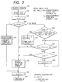
- FIG. 2 is a flowchart of assistance in explaining a method for detecting a rotation angular speed by the control part 14 of the rotation angular speed detection apparatus 11 of the present invention.
- ts 10 ms
- step S24 when the counter n is 0 (only the first time after the main power supply is turned on), a rotation angular speed cannot be obtained.
- the rotation angular speed is undefined (S25), and then, the counter n is counted up (S26) to end the routine (S27).
- a sign of a difference ⁇ (n)- ⁇ (n-1) between a first angle ⁇ (n) latest-stored and a second angle ⁇ (n-1) stored ts before the first angle ⁇ (n) is compared with a sign of a difference ⁇ (n-1)- ⁇ (n-2) between the second angle ⁇ (n-1) and an angle ⁇ (n-2) stored ts before the second angle ⁇ (n-1) (S29).
- step S29 when the sign of the difference ⁇ (n)- ⁇ (n-1) between the first angle and the second angle is different from the sign of the difference ⁇ (n-1)- ⁇ (n-2) between the second angle and the angle stored ts before the second angle (Y), the second angle ⁇ (n-1) is ⁇ (0), the first angle ⁇ (n) is ⁇ (1), the counter n is 1 (S30).
- step S31 the difference
- between the first angle and the angle stored ts ⁇ before the first angle is less than the predetermined value ⁇ s (Y), the counter ⁇ is compared with the counter n (S32).
- step S32 the counter ⁇ is equal to the counter n (Y), an angle in which a difference between the first angle ⁇ (n) and the angle is more than the predetermined value ⁇ s is not present in the stored angles.
- the oldest angle ⁇ (0) of the stored angles is a fourth angle.
- the counter ⁇ and the counter n are not equal (N)
- the counter ⁇ is counted up (S33) to return the routine to step S31.
- the routine is repeated.
- a difference between the first angle of the stored angles and another one angle selected is divided by a difference in time storing two angles to detect a rotation angular speed.
- the third angle ⁇ (n- ⁇ ) in which the difference between the first angle ⁇ (n) and the third angle ⁇ (n- ⁇ ) is more than the predetermined value ⁇ s is determined from the stored angles, and the difference ⁇ (n)- ⁇ (n- ⁇ ) between the first angle and the third angle is divided by the time ts ⁇ required from storing of the third angel to storing of the first angle so as to detect the rotation angular speed.
- the rotation angular speed can be detected using a sufficiently large angle ⁇ s (e.g., 10° or more) as compared with an error (the total of a measurement error of the rotation angle due to the accuracy of the angle sensor, an error at reception due to electric delay, and an error at converting an analog signal to a digital signal, e.g., 0.2°).
- the rotation angular speed having high accuracy e.g., an error rate of below 2%) can be detected.
- the step S32 is a process when the angle in which the difference between the first angle ⁇ (n) and the angle is more than the predetermined value ⁇ s is not present in the stored angles.
- the angle in which the difference between the first angle ⁇ (n) and the angle is more than the predetermined value ⁇ s is not present, as arbitrary angle of the stored angles, such as the oldest angle ⁇ (0) of the stored angles is a fourth angle, for example.
- the difference is divided by the longest time interval (ts ⁇ ) for storing the stored angles.
- the error rate is low (the difference is divided by ts in the prior art) so as to detect the rotation angular speed having high accuracy.
- the arbitrary angle of the angles stored before the first angle ⁇ (n) is selected from the angles stored in the storage part 13 as the fourth angle.
- the error rate can be reduced as compared with the prior art rotation angular speed apparatus so as to naturally detect the rotation angular speed having high accuracy.
- the steps S29 and S30 are processes when the rotation direction of the rotating body 16 is reversed.
- the two steps erase the angles before the rotation direction of the rotating body 16 is reversed.
- the routine does not go back to the angle before the rotation direction is reversed.
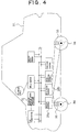
- FIG. 3 is a diagram showing the construction of an automobile using the rotation angular speed detection apparatus 11 of the present invention.
- the same constructions as in FIG. 1 are indicated by similar numerals, and the detailed description thereof is omitted.
- an automobile 31 of the present invention has the rotation angular speed detection apparatus 11 and the vehicle stability control system 18 for stabilizing a vehicle.
- the rotation angular speed detection apparatus 11 receives an angular signal from the angle sensor 17 for detecting the rotation angle of the steering wheel 16 as the rotating body with respect to the reference angle so as to detect a rotation angular speed of the steering wheel 16, and then, sends a rotation angular speed signal based on the detected rotation angular speed to the vehicle stability control system 18.
- the vehicle stability control system 18 is a control system for safely driving a vehicle including braking control 18a, suspension control 18b, auto-leveling control 18c, and traction control 18d.
- the vehicle stability control system 18 receives a rotation angular speed signal based on the rotation angular speed of the steering wheel 16 detected by the rotation angular speed detection apparatus 11. Then, the vehicle stability control system 18 predicts the traveling direction intended by the driver (the direction to finish turning the steering wheel) from the rotation angular speed of the steering wheel 16 based on the received rotation angular speed signal so as to safely control the vehicle.
- the rotation angular speed detection apparatus 11 is connected through a CAN (Controller Area Network) transceiver 32 to a communication BUS 33 to a LAN system in the vehicle as a multiplex transmission path, so as to be mutually communicated with the vehicle stability control system 18 also connected to the communication BUS 33 or with a vehicle speed sensor 49 for detecting the speed of the vehicle.
- CAN Controller Area Network
- FIG. 4 is a diagram showing an embodiment of the automobile 31 of the present invention.
- a sending signal from the rotation angular speed detection apparatus 11 is received by the braking control 18a for controlling front/rear brakes 34.
- a control signal sent from the braking control 18a controls the front/rear brakes 34.
- the sending signal from the rotation angular speed detection apparatus 11 is received by the suspension control 18b for controlling front/rear suspensions 35.
- a control signal sent from the suspension control 18b controls the front/rear suspensions 35.
- the total vehicle stability control is performed in this manner.
- the automobile 31 uses the rotation angular speed detection apparatus 11 of the present invention. An error is reduced when the traveling direction intended by the driver is predicted, so that the suitable vehicle stability control is possible. The automobile 31 can thus be driven more safely.
- a rotation angular speed detection apparatus comprises: a receiving part for receiving an angular signal at predetermined time intervals from a rotation angle sensor for detecting a rotation angle of a rotating body with respect to the reference angle; a storage part for storing the rotation angle based on the received angular signal; and a control part for dividing a difference between a first arbitrary angle of the rotation angles stored in the storage part and a second angle stored before the first angle by the time required from storing of the second angle to storing of the first angle so as to detect a rotation angular speed; wherein when the difference between the first angle and the second angle is less than a predetermined value, the control part determines, from the angles stored in the storage part, a third angle stored before the second angle in which a difference between the first angle and the third angle is more than the predetermined value, and wherein the control part divides the difference between the first angle and the third angle by the time required from storing of the third angle to storing of the first angle so as
- an automobile comprises: the rotation angular speed detection apparatus; and a vehicle stability control system for stabilizing a vehicle; wherein the rotation angular speed detection apparatus receives an angular signal from an angle sensor detecting a rotation angle of a steering wheel so as to detect a rotation angular speed of the steering wheel, and wherein a rotation angular speed signal based on the detected rotation angular speed is sent to the vehicle stability control system.
- the present invention can provide an automobile which can predict the traveling direction intended by the driver more precisely and permits suitable vehicle stability control.
Abstract
Description
In the present invention, when no difference between the first angle and any of the rotation angles stored in the storage part is more than the predetermined value, the control part selects an arbitrary rotation angle of the rotation angles stored before the first angle in the storage part as a fourth angle, and divides a difference between the first angle and the fourth angle by a time required from storing of the fourth angle to storing of the first angle so as to detect a rotation angular speed.
Claims (9)
- A rotation angular speed detection apparatus comprising:wherein when the difference between the first angle and the second angle is less than a predetermined value, the control part determines, from the rotation angles stored in the storage part, a third angle stored before the second angle in which a difference between the first angle and the third angle is more than the predetermined value, and wherein the control part divides the difference between the first angle and the third angle by a time required from storing of the third angle to storing of the first angle to detect the rotation angular speed.a receiving part to receive an angular signal at predetermined time intervals from a rotation angle sensor that detects a rotation angle of a rotating body with respect to a reference angle;a storage part to store the rotation angle based on the received angular signal; anda control part to divide a difference between a first arbitrary angle of the rotation angles stored in the storage part and a second angle stored before the first angle by a time required from storing of the second angle to storing of the first angle to detect a rotation angular speed;
- The rotation angular speed detection apparatus according to claim 1, wherein when no difference between the first angle and any of the rotation angles stored in the storage part is more than the predetermined value, the control part selects an arbitrary rotation angle of the rotation angles stored before the first angle in the storage part as a fourth angle, and
wherein the control part divides a difference between the first angle and the fourth angle by a time required from storing of the fourth angle to storing of the first angle to detect the rotation angular speed. - The rotation angular speed detection apparatus according to claim 2, wherein when a sign of the difference between the first angle and the second angle is reversed from a sign of a difference between the second angle and the rotation angle stored immediately before the second angle, the control part erases the rotation angles stored before the second angle of the rotation angles stored in the storage part.
- A rotation angular speed detection method comprising:wherein when the difference is less than a predetermined value, a third angle stored before the second angle in which a difference between the first angle and the third angle is more than the predetermined value, is determined from the stored rotation angles, anddetecting a rotation angle of a rotating body at predetermined time intervals;storing the detected rotation angle;determining a difference between a first arbitrary angle of the stored rotation angles and a second angle stored before the first angle; anddetecting a rotation angle speed by dividing the difference by a time required from storing of the second angle to storing of the first angle to detect a rotation angular speed;
the difference between the first angle and the third angle is divided by a time required from storing of the third angle to storing of the first angle to detect a rotation angular speed. - The rotation angular speed detection method according to claim 4, wherein when no difference between the first angle and any rotation angles of the stored rotation angles is more than the predetermined value, an arbitrary rotation angle of the rotation angles stored before the first angle is selected as a fourth angle;
wherein a difference between the first angle and the fourth angle is divided by a time required from storing of the fourth angle to storing of the first angle to detect the rotation angular speed. - The rotation angular speed detection method according to claim 5, wherein when a sign of a difference between the first angle and the second angle is reversed from a sign of a difference between the second angle and a rotation angle stored immediately before the second angle, the angles stored before the second angle of the stored rotation angles are erased.
- An automobile comprising:wherein the rotation angular speed detection apparatus receives an angular signal from an angle sensor detecting a rotation angle of a steering wheel so as to detect a rotation angular speed of the steering wheel, andthe rotation angular speed detection apparatus according to claim 1; anda vehicle stability control system to stabilize a vehicle;
wherein a rotation angular speed signal based on the detected rotation angular speed of the steering wheel is sent to the vehicle stability control system. - The rotation angular speed detection apparatus according to claim 7, wherein when no difference between the first angle and any of the rotation angles stored in the storage part is more than the predetermined value, the control part in the rotation angular speed detection apparatus selects an arbitrary rotation angle of the rotation angles stored before the first angle in the storage part as a fourth angle, and
wherein the control part divides a difference between the first angle and the fourth angle by a time required from storing of the fourth angle to storing of the first angle to detect the rotation angular speed. - The rotation angular speed detection apparatus according to claim 8, wherein when a sign of the difference between the first angle and the second angle is reversed from a sign of a difference between the second angle and a rotation angle stored immediately before the second angle, the control part erases the rotation angles stored before the second angle of the rotation angles stored in the storage part.
Applications Claiming Priority (2)
| Application Number | Priority Date | Filing Date | Title |
|---|---|---|---|
| JP2000273552 | 2000-09-05 | ||
| JP2000273552A JP3621335B2 (en) | 2000-09-05 | 2000-09-05 | Rotational angular velocity detection device, rotational angular velocity detection method, and automobile using the device |
Publications (2)
| Publication Number | Publication Date |
|---|---|
| EP1186515A2 true EP1186515A2 (en) | 2002-03-13 |
| EP1186515A3 EP1186515A3 (en) | 2005-12-07 |
Family
ID=18759469
Family Applications (1)
| Application Number | Title | Priority Date | Filing Date |
|---|---|---|---|
| EP01121181A Withdrawn EP1186515A3 (en) | 2000-09-05 | 2001-09-04 | Apparatus and method for detecting rotation angular speed and automobile using the apparatus |
Country Status (3)
| Country | Link |
|---|---|
| US (1) | US6463399B1 (en) |
| EP (1) | EP1186515A3 (en) |
| JP (1) | JP3621335B2 (en) |
Families Citing this family (4)
| Publication number | Priority date | Publication date | Assignee | Title |
|---|---|---|---|---|
| FI20020400A0 (en) * | 2002-03-01 | 2002-03-01 | Nokia Corp | Determining the direction of a signal in a radio system |
| JP5294597B2 (en) * | 2007-09-20 | 2013-09-18 | 株式会社ミツバ | Motor rotation speed calculation method and wiper device |
| JP5288478B2 (en) * | 2009-04-15 | 2013-09-11 | クラリオン株式会社 | Vehicle speed pulse detector |
| CN108170148B (en) * | 2018-01-08 | 2021-07-27 | 天津英创汇智汽车技术有限公司 | Control method and device of domain controller for automatic driving |
Citations (3)
| Publication number | Priority date | Publication date | Assignee | Title |
|---|---|---|---|---|
| US4734655A (en) * | 1985-10-04 | 1988-03-29 | Mitsubishi Denki Kabushiki Kaisha | Digital rotation detecting apparatus |
| DE3709395A1 (en) * | 1987-03-21 | 1988-09-29 | Licentia Gmbh | Method and device for digitally determining a number proportional to rotational speed of a body |
| US4874053A (en) * | 1987-06-22 | 1989-10-17 | Hitachi, Ltd. | Torque detecting apparatus |
Family Cites Families (6)
| Publication number | Priority date | Publication date | Assignee | Title |
|---|---|---|---|---|
| JP3425298B2 (en) * | 1996-06-05 | 2003-07-14 | アルプス電気株式会社 | Rudder angle sensor unit |
| JP3668614B2 (en) | 1998-07-13 | 2005-07-06 | 光洋精工株式会社 | Power steering device |
| US6314355B1 (en) * | 1999-07-12 | 2001-11-06 | Alps Electric Co., Ltd. | Steering angle detecting mechanism |
| JP2001114116A (en) * | 1999-10-19 | 2001-04-24 | Alps Electric Co Ltd | Rotation angle detecting device |
| JP2001174289A (en) * | 1999-12-17 | 2001-06-29 | Alps Electric Co Ltd | Detector for angular rotation |
| JP2001241942A (en) * | 2000-02-25 | 2001-09-07 | Alps Electric Co Ltd | Device for detecting angle of rotation |
-
2000
- 2000-09-05 JP JP2000273552A patent/JP3621335B2/en not_active Expired - Fee Related
-
2001
- 2001-09-04 EP EP01121181A patent/EP1186515A3/en not_active Withdrawn
- 2001-09-05 US US09/947,156 patent/US6463399B1/en not_active Expired - Fee Related
Patent Citations (3)
| Publication number | Priority date | Publication date | Assignee | Title |
|---|---|---|---|---|
| US4734655A (en) * | 1985-10-04 | 1988-03-29 | Mitsubishi Denki Kabushiki Kaisha | Digital rotation detecting apparatus |
| DE3709395A1 (en) * | 1987-03-21 | 1988-09-29 | Licentia Gmbh | Method and device for digitally determining a number proportional to rotational speed of a body |
| US4874053A (en) * | 1987-06-22 | 1989-10-17 | Hitachi, Ltd. | Torque detecting apparatus |
Also Published As
| Publication number | Publication date |
|---|---|
| JP3621335B2 (en) | 2005-02-16 |
| JP2002082124A (en) | 2002-03-22 |
| US6463399B1 (en) | 2002-10-08 |
| EP1186515A3 (en) | 2005-12-07 |
| US20020029126A1 (en) | 2002-03-07 |
Similar Documents
| Publication | Publication Date | Title |
|---|---|---|
| US7966118B2 (en) | Automatic time headway setting for adaptive cruise control system | |
| JP3171119B2 (en) | Automatic driving control device for vehicles | |
| US8065057B2 (en) | Process and apparatus for the sway stabilization of a motor vehicle | |
| US5787376A (en) | Power steering motor control unit with driving mode correction | |
| US20080262676A1 (en) | Steering retention state judging device, driver wakefulness predicting device, and correct course keeping device | |
| EP1394015A2 (en) | Electric power steering apparatus. | |
| JP2002104221A (en) | Traffic lane follow-up control device | |
| EP2042357B1 (en) | Stabilizer control device, stabilizer control method and stabilizer control program | |
| US20040189454A1 (en) | Sensor device for detecting and transmitting vehicle motion data | |
| EP1186515A2 (en) | Apparatus and method for detecting rotation angular speed and automobile using the apparatus | |
| EP1211157A2 (en) | Electric power steering controller | |
| JP2003285688A (en) | Device and method for adjusting view range of vehicular monitoring device | |
| JP3168820B2 (en) | Vehicle acceleration sensor correction device | |
| US6984059B2 (en) | Vehicular headlight axis control device | |
| KR100839123B1 (en) | System for controlling a vehicle electronically and sensor offset correction method therefor | |
| US6763293B2 (en) | Calibration procedure for a permanently powered relative steering wheel angle sensor with power-loss indication | |
| US20050182542A1 (en) | Device and procedure for a steering support for vehicles with electromechanical steering system | |
| US7936138B2 (en) | Motor controller for radio control | |
| JP5800971B1 (en) | Lane driving support device | |
| JPH06199156A (en) | Control gain changing device for automobile control device | |
| US8504296B2 (en) | Method for determining an item of travel direction information for a vehicle, and sensor device for a vehicle | |
| KR20090062528A (en) | System for correcting directivity of radar | |
| JP2003212042A (en) | Method and device of automatically adjusting view angle of rearview mirror for vehicle | |
| JPH07132845A (en) | Electric power steering with learning function | |
| JPH0999853A (en) | Front/rear wheel steering device for vehicle |
Legal Events
| Date | Code | Title | Description |
|---|---|---|---|
| PUAI | Public reference made under article 153(3) epc to a published international application that has entered the european phase |
Free format text: ORIGINAL CODE: 0009012 |
|
| AK | Designated contracting states |
Kind code of ref document: A2 Designated state(s): AT BE CH CY DE DK ES FI FR GB GR IE IT LI LU MC NL PT SE TR |
|
| AX | Request for extension of the european patent |
Free format text: AL;LT;LV;MK;RO;SI |
|
| PUAL | Search report despatched |
Free format text: ORIGINAL CODE: 0009013 |
|
| AK | Designated contracting states |
Kind code of ref document: A3 Designated state(s): AT BE CH CY DE DK ES FI FR GB GR IE IT LI LU MC NL PT SE TR |
|
| AX | Request for extension of the european patent |
Extension state: AL LT LV MK RO SI |
|
| AKX | Designation fees paid | ||
| STAA | Information on the status of an ep patent application or granted ep patent |
Free format text: STATUS: THE APPLICATION IS DEEMED TO BE WITHDRAWN |
|
| 18D | Application deemed to be withdrawn |
Effective date: 20060608 |
|
| REG | Reference to a national code |
Ref country code: DE Ref legal event code: 8566 |