JP3668614B2 - Power steering device - Google Patents
Power steering device Download PDFInfo
- Publication number
- JP3668614B2 JP3668614B2 JP19761498A JP19761498A JP3668614B2 JP 3668614 B2 JP3668614 B2 JP 3668614B2 JP 19761498 A JP19761498 A JP 19761498A JP 19761498 A JP19761498 A JP 19761498A JP 3668614 B2 JP3668614 B2 JP 3668614B2
- Authority
- JP
- Japan
- Prior art keywords
- steering
- state
- current
- vehicle speed
- value
- Prior art date
- Legal status (The legal status is an assumption and is not a legal conclusion. Google has not performed a legal analysis and makes no representation as to the accuracy of the status listed.)
- Expired - Fee Related
Links
Images
Classifications
-
- B—PERFORMING OPERATIONS; TRANSPORTING
- B62—LAND VEHICLES FOR TRAVELLING OTHERWISE THAN ON RAILS
- B62D—MOTOR VEHICLES; TRAILERS
- B62D5/00—Power-assisted or power-driven steering
- B62D5/06—Power-assisted or power-driven steering fluid, i.e. using a pressurised fluid for most or all the force required for steering a vehicle
- B62D5/065—Power-assisted or power-driven steering fluid, i.e. using a pressurised fluid for most or all the force required for steering a vehicle characterised by specially adapted means for varying pressurised fluid supply based on need, e.g. on-demand, variable assist
Landscapes
- Engineering & Computer Science (AREA)
- Chemical & Material Sciences (AREA)
- Combustion & Propulsion (AREA)
- Transportation (AREA)
- Mechanical Engineering (AREA)
- Steering Control In Accordance With Driving Conditions (AREA)
- Power Steering Mechanism (AREA)
Description
【0001】
【発明の属する技術分野】
本発明は、電動モータ駆動ポンプの発生油圧によりステアリング機構に操舵補助力を与えるパワーステアリング装置に関するものである。
【0002】
【従来の技術】
ステアリング機構に結合されたパワーシリンダにオイルポンプからの作動油を供給することにより、ステアリングホイールの操舵を補助するパワーステアリング装置が使用されている。オイルポンプは電動モータによって駆動され、その回転数に応じた操舵補助力がパワーシリンダから発生する。ステアリングが切り込まれていない状態では操舵補助力を要しないから、ステアリングが操舵中点近傍にある直進操舵状態(非操舵時)においては、電動モータを停止させ、操舵に連動する何らかの条件の変化が検出されたことに応答して電動モータを起動している。
【0003】
また、電力を節約し、油圧の立ち上がりをスムーズにするため、非操舵時においても、電動モータを低電圧で駆動するスタンバイ駆動が行われることも多くなっている。
【0004】
前記電動モータの制御においては、操舵時から非操舵に切り変わるタイミングの検出方法が種々考えられる。
【0005】
例えば、電動モータに流れる電流がステアリングトルクに応じて変化することに着目し、当該電流を検知して、当該検知電流の絶対値あるいは無負荷時の電流値からの相対変化量がしきい値を下回ったことで、電動モータを停止又は最小回転数にするという制御が提案されている(特開平5−69844号公報参照)。
【0006】
【発明が解決しようとする課題】
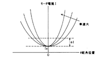
ところが、前述の制御方法では、舵角位置に対する電動モータ電流曲線は、図6に示すように、車速によって変化するため、一定の電流のしきい値ΔIに基づく判定では、車速の違いにより、モータ停止状態又はスタンバイ状態に入る舵角位置に違いが出てきて、ステアリング操作のフィーリングに変化が出てしまう。
【0007】
そこで、本発明は、車速の違いにかかわらず、ステアリング操作フィーリングが変化しないパワーステアリング装置を実現することを目的とする。
【0011】
【課題を解決するための手段】
本発明のパワーステアリング装置によれば、制御手段は、(a) 第1状態で、舵角の変化率dθ/dtが所定値以下であるかどうか、(b) 第1状態で、電流センサから検出される電流Iが、無負荷電流値I0から無負荷電流値I0に電流のしきい値ΔIを加えた範囲内にあるか、もしくは電流のしきい値ΔI以下であるかどうか、(c) 第1状態で、舵角θが中点から左右しきい値±Δθの範囲内にあるかどうかを判定する手段と、前記舵角のしきい値Δθを車両の速度に応じて変化する値として求める手段とを備え、
前記(a) の条件が満たされることと、前記(b) の条件が満たされることと、前記(c) の条件が満たされることの全部に基づいて、第1状態を第2状態に切り換えるものである。前記しきい値Δθは、車速が大きくなれば徐々に減少し、車速が小さいほど増加し、ある一定の車速よりも小さくなると、急激に増加する連続的特性を有するものである。この発明のパワーステアリング装置によれば、保舵状態(舵角の変化率dθ/dt≦所定値)であることを前提にして、電流センサから検出される電流Iが
I0≦I≦I0+ΔI もしくは 0≦I<ΔI (1)
を満たしているかどうか、及び舵角θが舵角中点から左右しきい値±Δθの範囲内にあるかどうか
θ0−Δθ<θ<θ0+Δθ (θ0は舵角中点を表す) (2)
を判定し、全部満たしていれば、アシスト状態からストップ状態もしくはスタンバイ状態に切り換える。ここでI 0 は、無負荷電流であり、ストップ状態であればI 0 =0、スタンバイ状態であれば作動油の温度等によって決まる値をとる。
【0012】
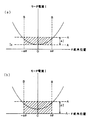
図2(a),(b) は、この判定条件を示すグラフであり、前記(1)式で特定される範囲を横線A−Aで示し、前記(2)式で特定される範囲を縦線B−Bで示す。
【0013】
この発明では、前記舵角のしきい値Δθを車両の速度に応じて変化する値として求めるので、前記縦線B−Bで制限される範囲は、車速に応じて変化する値となる。
【0014】
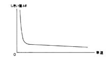
図3は、舵角のしきい値Δθと車速との関係を示したグラフである。車速が小さいほど舵角のしきい値Δθが高くなり、ある一定の車速よりも小さくなると、舵角のしきい値Δθは、急激に増加する。舵角のしきい値Δθが急増すると、舵角がどの位置にあっても前記(2)式は満たされるので、前記(2)式は実質的には条件として働かないことになる。一方、車速が大きくなれば舵角のしきい値Δθは徐々に減少していく。これにより車速が速くなるほど、ストップ状態もしくはスタンバイ状態となる舵角の範囲は狭くなることが判る。 このように舵角のしきい値Δθと車速との関係を設定したのは、停車時に、舵角の位置にかかわらず、操舵していない場合には、アシスト状態からストップ状態又はスタンバイ状態に切り換えるためである。また、ある程度以上の速度で走行していると、舵角が中点付近にあれば、ほぼ直進走行中で、非操舵状態と判断できるからである。
【0015】
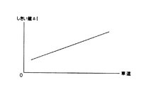
請求項2記載のパワーステアリング装置によれば、前記制御手段は、前記電流のしきい値ΔIを車両の速度に応じて変化する値として求める手段をさらに備えている。図1は、電流のしきい値ΔIと車速との関係を示したグラフである。車速が小さいほど電流のしきい値ΔIが低くなり、車速が大きいほど電流のしきい値ΔIは高くなっているので、図6に示したグラフと合わせてみると、アシスト状態からストップ状態もしくはスタンバイ状態に切り換えるハンドルの舵角位置は、一定に近づくのが判る。したがって、車速の違いにかかわらず、ステアリング操作フィーリングを一定にすることができる。
【0016】
このパワーステアリング装置によれば、前記舵角のしきい値Δθを車両の速度に応じて変化する値として求めるとともに、電流のしきい値ΔIを車両の速度に応じて変化する値として求める。したがって、図2(a) (b) を参照すれば、前記(1)式で特定される範囲A−Aと、前記(2)式で特定される範囲B−Bが、ともに車速に応じて変動することになる。
【0017】
以上の制御手段は、第1状態を第2状態に切り換える場合に、当該切り換えの条件が一定時間にわたって継続していることを条件とするタイマー手段をさらに有することが好ましい(請求項3)。
【0018】
この構成であれば、不整地走行などにおいて、当該切り換えが不用意に行われるのを防止することができる。
【0019】
【発明の実施の形態】
以下、本発明の実施の形態を、添付図面を参照しながら詳細に説明する。
【0020】
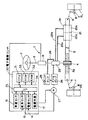
図4は、パワーステアリング装置の基本的な構成を示すブロック図である。
【0021】
ステアリング機構1は、ドライバによって操作されるステアリングホイール2と、このステアリングホイール2に連結されたステアリング軸3と、ステアリング軸3の先端部に設けられたピニオンギア4と、このピニオンギア4にかみ合うラックギア部5aを有し、車両の左右方向に延びたラック軸5を有している。
【0022】
ラック軸5の両端にはタイロッド6がそれぞれ結合されており、このタイロッド6は、それぞれ、操舵輪であるフロント左右輪FL,FRを支持するナックルアーム7に結合されている。ナックルアーム7は、キングピン8を中心として回転自在である。
【0023】
以上の構成において、ステアリングホイール2の操作によりステアリング軸3が回転すると、この回転がピニオンギア4及びラック軸5によって車両の左右方向に沿う直線運動に変換され、これによって、フロント左右輪FL,FRの操舵が行われる。
【0024】
ステアリング軸3の途中には、ステアリングホイール2に加えられた操舵トルクの方向及び大きさに応じてねじれを生じるトーションバー9と、このトーションバー9のねじれの方向及び大きさに応じて開度が変化する油圧制御弁23が設けられている。この油圧制御弁23は、ステアリング機構1に操舵補助力を与えるパワーシリンダ20に接続されている。パワーシリンダ20は、ラック軸5に一体的に設けられたピストン21と、このピストン21によって区画された一対のシリンダ室20a,20bとを有しており、シリンダ室20a,20bは、それぞれオイル供給/帰還路22a,22bを介して油圧制御弁23に接続されている。
【0025】
油圧制御弁23は、さらに、リザーバタンク25及びオイルポンプ26を通るオイル循環路24にも入っている。オイルポンプ26は、電動モータ27によって駆動され、リザーバタンク25に溜められている作動油を汲み出して油圧制御弁23に供給する。余剰の作動油は、油圧制御弁23からオイル循環路24を通ってリザーバタンク25に戻される。
【0026】
油圧制御弁23は、トーションバー9に一方向のねじれが加わった場合には、オイル供給/帰還路22a,22bのうち一方を介してパワーシリンダ20のシリンダ室20a,20bのうち一方に作動油を供給する。また、トーションバー9に他方方向のねじれが加わった場合には、オイル供給/帰還路22a,22bのうち他方を介してパワーシリンダ20のシリンダ室20a,20bのうち他方に作動油を供給する。トーションバー9にねじれがほとんど加わっていない場合には、油圧制御弁23は、いわば平衡状態になり、作動油はパワーシリンダ20に供給されることなく、オイル循環路24を循環する。
【0027】
パワーシリンダ20のいずれかのシリンダ室に作動油が供給されると、ピストン21が車幅方向に沿って移動する。これにより、ラック軸5に操舵補助力が作用することになる(パワーアシスト)。なお、油圧制御弁に関連する動作については、特開昭59-118577号公報などを参照。操舵補助力の大きさは、オイルポンプ26を作動させる電動モータ27への印加電圧を制御することによって調整する。
【0028】
電動モータ27は、電子制御ユニット30によって回転制御される。電子制御ユニット30は、CPU31、CPU31のワークエリアなどを提供するRAM32、及びCPU31の動作プログラム、車速の関数としての電流のしきい値ΔI、車速の関数としての舵角のしきい値Δθなどを記憶したROM33と、これらを相互接続するバス34と、入出力部35と、この入出力部35に接続され、電動モータ27に流れる電流を検出する電流センサ14と、電動モータ27を駆動する駆動回路17とを有している。
【0029】
また、電子制御ユニット30には、舵角センサ15と、車速センサ16とが接続されている。
【0030】
車速センサ16は、例えば車輪の回転数を検出する車輪速センサなどが使用されるが、車両にABS(アンチロックブレーキシステム)が搭載されていれば、ABSユニットの車速センサから車速信号を取り込むようにしてもよい。
【0031】
舵角センサ15は、ステアリングホイールに関連して設けられており、イグニッションキースイッチが導通されてエンジンが始動したときのステアリングホイール2の舵角を初期値0として、この初期値からの相対舵角を検出する。
【0032】
本発明の実施形態においては、非操舵時において電動モータ27を駆動しないストップアンドゴー制御を採用する。しかし、ステアリング操作の引っかかり感をなくし、電動モータ27の起動をスムーズにするため、非操舵時においても、電動モータ27を低電圧で駆動するスタンバイ制御を行っている場合にも、本発明の適用が可能であることはいうまでもない。
【0033】
電子制御ユニット30は、操舵時、電動モータ27にパワーアシストに十分な電圧V1 を印加しており、後述する条件下で電動モータ27を停止する。
【0034】
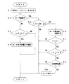
電動モータの状態を切り換える条件をフローチャート(図5)を用いて説明する。
【0035】
イグニションスイッチオンなどにより、電子制御ユニット30が立ち上げられると、CPU31は、舵角センサ15から出力される舵角データに基づいて、舵角θ及びその変化率dθ/dtを求める(ステップS1)。
【0036】
そして、電動モータ27が駆動中であるかどうかを判断する(ステップS2)。
【0037】
駆動中でなければ、舵角の変化率dθ/dtの絶対値としきい値a(例えばa=5degree/sec)との比較に基づいて電動モータを起動するかどうかを判断する(ステップS3,S4)。なお、電動モータの起動条件は、舵角の変化率判定に限られるものでなく、他の公知条件を当てはめることもできる。
【0038】
電動モータが駆動中であれば、CPU31は、舵角の変化率dθ/dtの絶対値が所定のしきい値b以下であるかどうかを判断する(ステップS5)。このしきい値bは、前記しきい値aと同程度の値であり、好ましくは、b>aにとられる(例えばb=8degree/sec)。b>aとするのは、操舵が開始されたときは操舵補助力を速やかに発生させ、操舵完了時には操舵補助を速やかに停止させるためである。
【0039】
舵角の変化率dθ/dtの絶対値がしきい値b以下であれば、ステップS6に移行し、電流センサ14の出力から電流値Iを読み出し(ステップS6)、この読み出された電流値Iが、電流のしきい値ΔI以内にあるかどうかを判定する(ステップS7)。
【0040】
I<ΔI
この電流のしきい値ΔIは、操舵補助を不要とする電動モータ電流の範囲を確定するものである。本発明の実施形態においては、電流のしきい値ΔIは、車速センサ16の出力から読み出された車速の関数となっているところに特徴があり、当該関数値がROM33に格納されている。
【0041】
なお、スタンバイ制御を行っている場合は、無負荷電流値I0を求め、電流値Iが、
I0<I<I0+ΔI
を満たしているかどうかで判断する。なお無負荷電流値I0の値は作動油の温度等によって異なるので、例えば、サンプリングした電流値Iのうち最頻出電流値もしくは最小値を求めることによって知ることができる。
【0042】
電流値Iが、電流のしきい値ΔIに入っていれば(ステップS7のYES)、舵角θの絶対値が舵角のしきい値Δθ以内に入っているかどうかを調べる(ステップS8)。この舵角のしきい値Δθも、操舵補助を不要とする舵角範囲を確定するものである。なお、舵角中点の検出は、舵角センサ15から出力される舵角データをサンプリングし、最頻出舵角を求めることにより可能となる。
【0043】
本発明の実施形態においては、舵角のしきい値Δθは、車速センサ16の出力から読み出された車速の関数となっていて、当該関数値がROM33に格納されている。
【0044】
舵角θの絶対値が、舵角のしきい値Δθ以内に入っていれば(ステップS8のYES)、以上に説明したステップS5,S7,S8を満たす状態が一定時間(例えば1〜3秒)継続したかどうかを判断する(ステップS9)。この判断の結果が肯定ならば、ステアリングホイールの操舵がないと判断できるから、CPU31は、電動モータ27を停止させる(ステップS10)。前記ステップS5,S7,S8,S9の判断のいずれかで、否定があれば、処理は元に戻る。
【0045】
以上の本発明の実施の形態では、電流のしきい値ΔI、舵角のしきい値Δθがともに車速の関数として、ROM33に記憶されているものであった。しかし、本発明の実施形態としては、これに限らず、電流のしきい値ΔI、舵角のしきい値Δθの少なくとも1つが車速の関数として記憶されているものであってもよい。さらに、電流のしきい値ΔI、舵角のしきい値Δθを車速に基づいて演算により求めることとしてもよい。
【0047】
【発明の効果】
以上のように本発明のパワーステアリング装置によれば、車速に応じてアシスト状態からストップ状態もしくはスタンバイ状態に切り換えるハンドルの舵角位置のしきい値を選ぶことができるので、車速の違いにかかわらず、ステアリング操作フィーリングを一定にすることができる。
【0048】
また、請求項2記載の本発明のパワーステアリング装置によれば、車速に応じてアシスト状態からストップ状態もしくはスタンバイ状態に切り換える電動モータ電流のしきい値を選ぶことができるので、車速の大小にかかわらず、アシスト状態からストップ状態もしくはスタンバイ状態に切り換えるハンドルの舵角位置を一定に近づけることができる。
【0049】
請求項3記載の本発明のパワーステアリング装置によれば、アシスト状態からストップ状態もしくはスタンバイ状態への切り換えが安定して行える。
【図面の簡単な説明】
【図1】電流のしきい値ΔIと車速との関係を示したグラフである。
【図2】舵角θの左右しきい値±Δθの範囲、及び電動モータ電流の電流のしきい値ΔIの範囲を示すグラフである。(a) は、I0<I<I0+ΔIの場合を示し、(b) は 0≦I<ΔIの場合を示す。
【図3】舵角のしきい値Δθと車速との関係を示したグラフである。
【図4】パワーステアリング装置の基本的な構成を示すブロック図である。
【図5】アシスト状態から電動モータ停止状態に切り換える条件を説明するためのフローチャートである。
【図6】舵角位置に対する電動モータ電流曲線を示すグラフであり、車速がパラメータとなっている。
【符号の説明】
14 電流センサ
15 舵角センサ
16 車速センサ
27 電動モータ
30 電子制御ユニット
31 CPU
32 RAM
33 ROM[0001]
BACKGROUND OF THE INVENTION
The present invention relates to a power steering device that applies a steering assist force to a steering mechanism by hydraulic pressure generated by an electric motor drive pump.
[0002]
[Prior art]
A power steering device that assists steering of a steering wheel by supplying hydraulic oil from an oil pump to a power cylinder coupled to a steering mechanism is used. The oil pump is driven by an electric motor, and a steering assist force corresponding to the rotation speed is generated from the power cylinder. Since the steering assist force is not required when the steering is not cut, the electric motor is stopped in a straight-ahead steering state where the steering is in the vicinity of the steering middle point (non-steering), and some condition change linked to the steering The electric motor is activated in response to the detection of.
[0003]
Further, in order to save electric power and make the hydraulic pressure rise smoothly, standby driving is often performed to drive the electric motor at a low voltage even during non-steering.
[0004]
In the control of the electric motor, various methods for detecting the timing of switching from steering to non-steering are conceivable.
[0005]
For example, focusing on the fact that the current flowing through the electric motor changes according to the steering torque, the current is detected, and the relative change amount from the absolute value of the detected current or the current value at the time of no load has a threshold value. There has been proposed a control for stopping the electric motor or setting it to the minimum number of revolutions because of lowering (see JP-A-5-69844).
[0006]
[Problems to be solved by the invention]
However, in the control method described above, the electric motor current curve with respect to the steering angle position changes depending on the vehicle speed, as shown in FIG. 6, and therefore in the determination based on the constant current threshold ΔI, A difference appears in the steering angle position to enter the stop state or the standby state, and the feeling of the steering operation changes.
[0007]
Therefore, an object of the present invention is to realize a power steering device in which the steering operation feeling does not change regardless of the vehicle speed.
[0011]
[Means for Solving the Problems]
According to the power steering apparatus of the present invention, the control means includes: (a) whether the steering angle change rate dθ / dt is less than or equal to a predetermined value in the first state, and (b) from the current sensor in the first state. Whether the detected current I is within the range of the no-load current value I 0 to the no-load current value I 0 plus the current threshold value ΔI, or whether the detected current I is equal to or less than the current threshold value ΔI. c) In the first state, the means for determining whether or not the steering angle θ is within the range of the left and right threshold values ± Δθ from the middle point, and the steering angle threshold value Δθ is changed according to the speed of the vehicle. A means for obtaining a value,
The first state is switched to the second state based on all of the conditions of (a) being satisfied, the conditions of (b) being satisfied, and the conditions of (c) being satisfied. It is. The threshold value Δθ has a continuous characteristic that gradually decreases as the vehicle speed increases, increases as the vehicle speed decreases, and rapidly increases when the vehicle speed decreases below a certain vehicle speed. According to the power steering apparatus of the present invention, the current I detected from the current sensor is I 0 ≦ I ≦ I 0 on the premise that the steering state is maintained (the rate of change of the steering angle dθ / dt ≦ predetermined value). + ΔI or 0 ≦ I <ΔI (1)
And whether the steering angle θ is within the range of left and right threshold values ± Δθ from the steering angle midpoint θ0−Δθ <θ <θ0 + Δθ (θ0 represents the steering angle midpoint) (2)
If all are satisfied, the assist state is switched to the stop state or the standby state. Here,
[0012]
2 (a) and 2 (b) are graphs showing the determination conditions. The range specified by the equation (1) is indicated by a horizontal line AA, and the range specified by the equation (2) is indicated by a vertical line. Indicated by line BB.
[0013]
In the present invention, since the steering angle threshold value Δθ is obtained as a value that varies depending on the vehicle speed, the range limited by the vertical line BB is a value that varies depending on the vehicle speed.
[0014]
FIG. 3 is a graph showing the relationship between the steering angle threshold value Δθ and the vehicle speed. The steering angle threshold value Δθ increases as the vehicle speed decreases, and the steering angle threshold value Δθ increases rapidly when the vehicle speed decreases below a certain fixed vehicle speed. If the steering angle threshold value Δθ increases rapidly, the equation (2) is satisfied regardless of the position of the steering angle, so the equation (2) does not substantially work as a condition. On the other hand, as the vehicle speed increases, the steering angle threshold value Δθ gradually decreases. Thus, it can be seen that the range of the steering angle in the stop state or the standby state becomes narrower as the vehicle speed increases. The relationship between the steering angle threshold value Δθ and the vehicle speed is set in this way when the vehicle is stopped, regardless of the position of the steering angle, when the steering is not performed, the assist state is switched to the stop state or the standby state. Because. In addition, if the vehicle is traveling at a speed of a certain level or more, if the rudder angle is in the vicinity of the middle point, it can be determined that the vehicle is traveling straight ahead and is not steered.
[0015]
According to the power steering apparatus 請 Motomeko 2, wherein the control means further comprises means for determining the threshold ΔI of the current as a value that changes depending on the speed of the vehicle. FIG. 1 is a graph showing the relationship between the current threshold value ΔI and the vehicle speed. The current threshold ΔI decreases as the vehicle speed decreases, and the current threshold ΔI increases as the vehicle speed increases. Therefore, when combined with the graph shown in FIG. It can be seen that the steering angle position of the steering wheel to be switched to a state approaches a constant value. Therefore, the steering operation feeling can be made constant regardless of the difference in vehicle speed.
[0016]
According to this power steering apparatus, the steering angle threshold value Δθ is obtained as a value that changes in accordance with the vehicle speed, and the current threshold value ΔI is obtained as a value that changes in accordance with the vehicle speed. Therefore, referring to FIGS. 2 (a) and 2 (b), the range A-A specified by the equation (1) and the range BB specified by the equation (2) are both in accordance with the vehicle speed. It will vary.
[0017]
Control means on the following, when switching the first state to the second state, may further include a timer means provided that the conditions of the switching is continued over a period of time (claim 3).
[0018]
With this configuration, it is possible to prevent the switching from being inadvertently performed on rough terrain.
[0019]
DETAILED DESCRIPTION OF THE INVENTION
Hereinafter, embodiments of the present invention will be described in detail with reference to the accompanying drawings.
[0020]
FIG. 4 is a block diagram showing a basic configuration of the power steering apparatus.
[0021]
The steering mechanism 1 includes a steering wheel 2 operated by a driver, a steering shaft 3 coupled to the steering wheel 2, a pinion gear 4 provided at the tip of the steering shaft 3, and a rack gear engaged with the pinion gear 4. The rack shaft 5 has a
[0022]
Tie rods 6 are coupled to both ends of the rack shaft 5, and the tie rods 6 are coupled to knuckle
[0023]
In the above configuration, when the steering shaft 3 is rotated by the operation of the steering wheel 2, this rotation is converted into a linear motion along the left-right direction of the vehicle by the pinion gear 4 and the rack shaft 5, and thereby the front left-right wheels FL, FR Is steered.
[0024]
In the middle of the steering shaft 3, a
[0025]
The
[0026]
When the
[0027]
When hydraulic oil is supplied to any cylinder chamber of the
[0028]
The
[0029]
Further, the
[0030]
As the
[0031]
The
[0032]
In the embodiment of the present invention, stop-and-go control that does not drive the
[0033]
The electronic control unit 30 applies a voltage V1 sufficient for power assist to the
[0034]
The conditions for switching the state of the electric motor will be described with reference to a flowchart (FIG. 5).
[0035]
When the electronic control unit 30 is started by turning on the ignition switch or the like, the
[0036]
Then, it is determined whether or not the
[0037]
If not driving, it is determined whether to start the electric motor based on a comparison between the absolute value of the steering angle change rate dθ / dt and a threshold value a (for example, a = 5 degree / sec) (steps S3 and S4). ). The starting condition of the electric motor is not limited to the determination of the change rate of the steering angle, and other known conditions can be applied.
[0038]
If the electric motor is being driven, the
[0039]
If the absolute value of the change rate dθ / dt of the steering angle is equal to or less than the threshold value b, the process proceeds to step S6, the current value I is read from the output of the current sensor 14 (step S6), and the read current value It is determined whether I is within the current threshold value ΔI (step S7).
[0040]
I <ΔI
The current threshold value ΔI determines the range of the electric motor current that does not require steering assistance. The embodiment of the present invention is characterized in that the current threshold value ΔI is a function of the vehicle speed read from the output of the
[0041]
When standby control is performed, the no-load current value I 0 is obtained, and the current value I is
I 0 <I <I 0 + ΔI
Judgment is made based on whether or not Since the value of the no-load current value I 0 varies depending on the temperature of the hydraulic oil and the like, for example, it can be known by obtaining the most frequently occurring current value or the minimum value among the sampled current values I.
[0042]
If the current value I is within the current threshold value ΔI (YES in step S7), it is checked whether or not the absolute value of the steering angle θ is within the steering angle threshold value Δθ (step S8). This steering angle threshold value Δθ also determines a steering angle range that does not require steering assistance. The steering angle midpoint can be detected by sampling the steering angle data output from the
[0043]
In the embodiment of the present invention, the steering angle threshold value Δθ is a function of the vehicle speed read from the output of the
[0044]
If the absolute value of the steering angle θ is within the steering angle threshold value Δθ (YES in step S8), the state in which the above-described steps S5, S7, S8 are satisfied for a certain period of time (eg, 1-3 seconds). ) It is determined whether or not the process has been continued (step S9). If the result of this determination is affirmative, it can be determined that there is no steering wheel steering, so the
[0045]
In the embodiment of the present invention described above, the current threshold value ΔI and the steering angle threshold value Δθ are both stored in the
[0047]
【The invention's effect】
As described above , according to the power steering device of the present invention, the threshold value of the steering angle position of the steering wheel that is switched from the assist state to the stop state or the standby state can be selected according to the vehicle speed, regardless of the difference in the vehicle speed. The steering operation feeling can be made constant.
[0048]
Further, according to the power steering device of the present invention described in claim 2, it is possible to choose a threshold value of the electric motor current is switched from the assist state to the stop state or a standby state according to the vehicle speed, regardless of the magnitude of the vehicle speed Therefore, the steering angle position of the steering wheel that is switched from the assist state to the stop state or the standby state can be made closer to a certain level.
[0049]
According to the power steering device of the present invention described in claim 3, performed by switching from the assist state to the stop state or the standby state is stabilized.
[Brief description of the drawings]
FIG. 1 is a graph showing a relationship between a current threshold value ΔI and a vehicle speed.
FIG. 2 is a graph showing a range of a left and right threshold value ± Δθ of a steering angle θ and a range of a current threshold value ΔI of an electric motor current. (a) shows the case of I 0 <I <I 0 + ΔI, and (b) shows the case of 0 ≦ I <ΔI.
FIG. 3 is a graph showing a relationship between a steering angle threshold value Δθ and a vehicle speed.
FIG. 4 is a block diagram showing a basic configuration of a power steering apparatus.
FIG. 5 is a flowchart for explaining a condition for switching from the assist state to the electric motor stop state.
FIG. 6 is a graph showing an electric motor current curve with respect to the steering angle position, where the vehicle speed is a parameter.
[Explanation of symbols]
14
32 RAM
33 ROM
Claims (3)
車両の速度を検出する車速センサと、電動モータに流れる電流を検出する電流センサと、
前記電動モータに操舵時に第1の電圧V1を印加する第1状態と、非操舵時に電動モータに電圧を印加しないか、もしくは前記第1の電圧よりも低い第2の電圧V2を印加する第2状態とを切り換えることのできる制御手段とを有し、
前記制御手段は、(a) 第1状態で、舵角の変化率dθ/dtが所定値以下であるかどうか、(b) 第1状態で、電流センサから検出される電流Iが、無負荷電流値I0から無負荷電流値I0に電流のしきい値ΔIを加えた範囲内にあるか、もしくは電流のしきい値ΔI以下であるかどうか、(c) 第1状態で、舵角θが中点から左右しきい値±Δθの範囲内にあるかどうかを判定する手段と、前記舵角のしきい値Δθを車両の速度に応じて変化する値として求める手段とを備え、
前記しきい値Δθは、車速が大きくなれば徐々に減少し、車速が小さいほど増加し、ある一定の車速よりも小さくなると、急激に増加する連続的特性を有するものであり、
前記(a) の条件が満たされることと、前記(b) の条件が満たされることと、前記(c) の条件が満たされることの全部に基づいて、第1状態を第2状態に切り換えることを特徴とするパワーステアリング装置。In a power steering device that generates a steering assist force by generated hydraulic pressure of a pump driven by an electric motor,
A vehicle speed sensor for detecting the speed of the vehicle, a current sensor for detecting a current flowing in the electric motor,
A first state in which the first voltage V1 is applied to the electric motor during steering, and a second state in which no voltage is applied to the electric motor during non-steering or a second voltage V2 lower than the first voltage is applied. Control means capable of switching between states,
The control means is (a) whether or not the steering angle change rate dθ / dt is less than or equal to a predetermined value in the first state, and (b) the current I detected from the current sensor in the first state is no load. or from the current value I 0 in the range plus a threshold ΔI of the current no-load current value I 0, or whether it is below the threshold ΔI of the current, (c) in the first state, steering angle means for determining whether θ is within a range of left and right threshold values ± Δθ from the middle point, and means for determining the steering angle threshold value Δθ as a value that changes according to the speed of the vehicle,
The threshold Δθ has a continuous characteristic that gradually decreases as the vehicle speed increases, increases as the vehicle speed decreases, and rapidly increases when the vehicle speed decreases below a certain vehicle speed.
The first state is switched to the second state based on all of the condition (a) being satisfied, the condition (b) being satisfied, and the condition (c) being satisfied. A power steering device.
Priority Applications (5)
| Application Number | Priority Date | Filing Date | Title |
|---|---|---|---|
| JP19761498A JP3668614B2 (en) | 1998-07-13 | 1998-07-13 | Power steering device |
| EP99113228A EP0972695B1 (en) | 1998-07-13 | 1999-07-08 | Power steering apparatus |
| DE69908865T DE69908865T2 (en) | 1998-07-13 | 1999-07-08 | Power steering |
| ES99113228T ES2196680T3 (en) | 1998-07-13 | 1999-07-08 | ASSISTED MANAGEMENT DEVICE. |
| US09/350,985 US6064166A (en) | 1998-07-13 | 1999-07-12 | Power steering apparatus |
Applications Claiming Priority (1)
| Application Number | Priority Date | Filing Date | Title |
|---|---|---|---|
| JP19761498A JP3668614B2 (en) | 1998-07-13 | 1998-07-13 | Power steering device |
Publications (2)
| Publication Number | Publication Date |
|---|---|
| JP2000025632A JP2000025632A (en) | 2000-01-25 |
| JP3668614B2 true JP3668614B2 (en) | 2005-07-06 |
Family
ID=16377411
Family Applications (1)
| Application Number | Title | Priority Date | Filing Date |
|---|---|---|---|
| JP19761498A Expired - Fee Related JP3668614B2 (en) | 1998-07-13 | 1998-07-13 | Power steering device |
Country Status (5)
| Country | Link |
|---|---|
| US (1) | US6064166A (en) |
| EP (1) | EP0972695B1 (en) |
| JP (1) | JP3668614B2 (en) |
| DE (1) | DE69908865T2 (en) |
| ES (1) | ES2196680T3 (en) |
Families Citing this family (13)
| Publication number | Priority date | Publication date | Assignee | Title |
|---|---|---|---|---|
| JP3673377B2 (en) * | 1997-09-26 | 2005-07-20 | 光洋精工株式会社 | Power steering device |
| JP3621335B2 (en) | 2000-09-05 | 2005-02-16 | アルプス電気株式会社 | Rotational angular velocity detection device, rotational angular velocity detection method, and automobile using the device |
| DE10325848A1 (en) * | 2003-06-06 | 2005-01-05 | Trw Fahrwerksysteme Gmbh & Co. Kg | Method for controlling an electric pump drive motor of a power steering device |
| US6941207B2 (en) * | 2003-10-10 | 2005-09-06 | Matsushita Electric Industrial Co., Ltd. | Steering angular velocity detecting device |
| JP4368742B2 (en) * | 2004-06-08 | 2009-11-18 | 株式会社日立製作所 | Power steering device |
| EP1752358A1 (en) * | 2005-08-10 | 2007-02-14 | Ford Global Technologies, LLC | Electro-hydraulic power steering and method of controlling the rotational speed of its pump |
| JP4796869B2 (en) * | 2006-03-03 | 2011-10-19 | 日立オートモティブシステムズ株式会社 | Power steering device |
| JP4984598B2 (en) * | 2006-03-30 | 2012-07-25 | 日本精工株式会社 | Electric power steering device |
| FR2935670B1 (en) * | 2008-09-11 | 2011-08-05 | Jtekt Hpi | METHOD OF STRATEGY FOR REDUCING THE ENERGY CONSUMPTION OF A MOTOR VEHICLE |
| US9637255B2 (en) * | 2012-12-26 | 2017-05-02 | The Raymond Corporation | Palletized load wrapping and transporting vehicle and method |
| CN104724165B (en) * | 2013-12-20 | 2017-01-25 | 北汽福田汽车股份有限公司 | Vehicle steering device, control method thereof and vehicle |
| JP7256062B2 (en) * | 2019-04-15 | 2023-04-11 | トヨタ自動車株式会社 | steering system |
| CN112238892B (en) * | 2019-07-19 | 2021-12-10 | 郑州宇通客车股份有限公司 | Steering system based on EPS and EHPS and control method thereof |
Family Cites Families (12)
| Publication number | Priority date | Publication date | Assignee | Title |
|---|---|---|---|---|
| JPS5722967A (en) * | 1980-07-16 | 1982-02-06 | Tokai T R W Kk | Power steering system |
| JPS57198169A (en) * | 1981-05-29 | 1982-12-04 | Tokai T R W Kk | Motor-driven oil pressure power steering unit |
| US4518055A (en) * | 1982-04-08 | 1985-05-21 | Nissan Motor Company, Limited | Pump-drive device of power-assisted steering system |
| JPS59118577A (en) | 1982-12-27 | 1984-07-09 | Koyo Jidoki Kk | Spool for rotary control valve of power steering gear and method of manufacturing said spool |
| JPS59149870A (en) * | 1983-02-14 | 1984-08-27 | Jidosha Kiki Co Ltd | Power steering gear |
| DE3920862A1 (en) * | 1989-06-26 | 1991-01-03 | Teves Gmbh Alfred | AUXILIARY STEERING FOR MOTOR VEHICLES |
| JPH0829716B2 (en) | 1991-09-17 | 1996-03-27 | 本田技研工業株式会社 | Power steering system controller |
| DE4241785B4 (en) * | 1992-12-11 | 2009-03-12 | Continental Teves Ag & Co. Ohg | Hydraulic power steering system |
| DE4335390B4 (en) * | 1993-10-16 | 2007-04-12 | Trw Fahrwerksysteme Gmbh & Co Kg | Power steering device |
| JP3479730B2 (en) * | 1994-10-20 | 2003-12-15 | 光洋精工株式会社 | Electric power steering device |
| JP3506810B2 (en) * | 1995-06-19 | 2004-03-15 | ユニシア ジェーケーシー ステアリングシステム株式会社 | Electric pump type power steering device |
| JP3547558B2 (en) * | 1995-10-25 | 2004-07-28 | 光洋精工株式会社 | Power steering device |
-
1998
- 1998-07-13 JP JP19761498A patent/JP3668614B2/en not_active Expired - Fee Related
-
1999
- 1999-07-08 DE DE69908865T patent/DE69908865T2/en not_active Expired - Lifetime
- 1999-07-08 EP EP99113228A patent/EP0972695B1/en not_active Expired - Lifetime
- 1999-07-08 ES ES99113228T patent/ES2196680T3/en not_active Expired - Lifetime
- 1999-07-12 US US09/350,985 patent/US6064166A/en not_active Expired - Lifetime
Also Published As
| Publication number | Publication date |
|---|---|
| US6064166A (en) | 2000-05-16 |
| JP2000025632A (en) | 2000-01-25 |
| EP0972695A3 (en) | 2001-06-27 |
| ES2196680T3 (en) | 2003-12-16 |
| EP0972695A2 (en) | 2000-01-19 |
| DE69908865D1 (en) | 2003-07-24 |
| DE69908865T2 (en) | 2004-05-06 |
| EP0972695B1 (en) | 2003-06-18 |
Similar Documents
| Publication | Publication Date | Title |
|---|---|---|
| US6216814B1 (en) | Power steering apparatus | |
| JP3546062B2 (en) | Power steering device | |
| JP3582839B2 (en) | Power steering device | |
| JP3668614B2 (en) | Power steering device | |
| JPWO1999008921A1 (en) | power steering device | |
| JPWO1999008922A1 (en) | power steering device | |
| JP3648392B2 (en) | Power steering device | |
| JP3673377B2 (en) | Power steering device | |
| US6250418B1 (en) | Power steering apparatus | |
| EP0987163B1 (en) | Power steering apparatus | |
| EP1043211B1 (en) | Power steering apparatus | |
| EP1900604B1 (en) | Power steering system | |
| JP2972283B2 (en) | Power steering control device | |
| JP2000159137A (en) | Power steering device | |
| JP3589810B2 (en) | Power steering device | |
| CA2497729C (en) | Power steering apparatus | |
| JP2002120741A (en) | Power steering device | |
| JPH11334631A (en) | Power steering system | |
| JP2001163239A (en) | Power steering device |
Legal Events
| Date | Code | Title | Description |
|---|---|---|---|
| A977 | Report on retrieval |
Free format text: JAPANESE INTERMEDIATE CODE: A971007 Effective date: 20041201 |
|
| A131 | Notification of reasons for refusal |
Free format text: JAPANESE INTERMEDIATE CODE: A131 Effective date: 20050106 |
|
| A521 | Request for written amendment filed |
Free format text: JAPANESE INTERMEDIATE CODE: A523 Effective date: 20050302 |
|
| TRDD | Decision of grant or rejection written | ||
| A01 | Written decision to grant a patent or to grant a registration (utility model) |
Free format text: JAPANESE INTERMEDIATE CODE: A01 Effective date: 20050322 |
|
| A61 | First payment of annual fees (during grant procedure) |
Free format text: JAPANESE INTERMEDIATE CODE: A61 Effective date: 20050411 |
|
| R150 | Certificate of patent or registration of utility model |
Free format text: JAPANESE INTERMEDIATE CODE: R150 |
|
| S533 | Written request for registration of change of name |
Free format text: JAPANESE INTERMEDIATE CODE: R313533 |
|
| R350 | Written notification of registration of transfer |
Free format text: JAPANESE INTERMEDIATE CODE: R350 |
|
| FPAY | Renewal fee payment (event date is renewal date of database) |
Free format text: PAYMENT UNTIL: 20080415 Year of fee payment: 3 |
|
| FPAY | Renewal fee payment (event date is renewal date of database) |
Free format text: PAYMENT UNTIL: 20090415 Year of fee payment: 4 |
|
| FPAY | Renewal fee payment (event date is renewal date of database) |
Free format text: PAYMENT UNTIL: 20090415 Year of fee payment: 4 |
|
| FPAY | Renewal fee payment (event date is renewal date of database) |
Free format text: PAYMENT UNTIL: 20100415 Year of fee payment: 5 |
|
| FPAY | Renewal fee payment (event date is renewal date of database) |
Free format text: PAYMENT UNTIL: 20100415 Year of fee payment: 5 |
|
| FPAY | Renewal fee payment (event date is renewal date of database) |
Free format text: PAYMENT UNTIL: 20110415 Year of fee payment: 6 |
|
| FPAY | Renewal fee payment (event date is renewal date of database) |
Free format text: PAYMENT UNTIL: 20120415 Year of fee payment: 7 |
|
| FPAY | Renewal fee payment (event date is renewal date of database) |
Free format text: PAYMENT UNTIL: 20130415 Year of fee payment: 8 |
|
| FPAY | Renewal fee payment (event date is renewal date of database) |
Free format text: PAYMENT UNTIL: 20140415 Year of fee payment: 9 |
|
| LAPS | Cancellation because of no payment of annual fees |