EP1186481A2 - Überrollschutzsystem für Kraftfahrzeuge - Google Patents
Überrollschutzsystem für Kraftfahrzeuge Download PDFInfo
- Publication number
- EP1186481A2 EP1186481A2 EP01118213A EP01118213A EP1186481A2 EP 1186481 A2 EP1186481 A2 EP 1186481A2 EP 01118213 A EP01118213 A EP 01118213A EP 01118213 A EP01118213 A EP 01118213A EP 1186481 A2 EP1186481 A2 EP 1186481A2
- Authority
- EP
- European Patent Office
- Prior art keywords
- locking
- rollover
- protection system
- rollover protection
- attached
- Prior art date
- Legal status (The legal status is an assumption and is not a legal conclusion. Google has not performed a legal analysis and makes no representation as to the accuracy of the status listed.)
- Granted
Links
Images


Classifications
-
- B—PERFORMING OPERATIONS; TRANSPORTING
- B60—VEHICLES IN GENERAL
- B60R—VEHICLES, VEHICLE FITTINGS, OR VEHICLE PARTS, NOT OTHERWISE PROVIDED FOR
- B60R21/00—Arrangements or fittings on vehicles for protecting or preventing injuries to occupants or pedestrians in case of accidents or other traffic risks
- B60R21/02—Occupant safety arrangements or fittings, e.g. crash pads
- B60R21/13—Roll-over protection
- B60R2021/132—Roll bars for convertible vehicles
- B60R2021/134—Roll bars for convertible vehicles movable from a retracted to a protection position
- B60R2021/135—Roll bars for convertible vehicles movable from a retracted to a protection position automatically during an accident
Definitions
- Rollover protection systems of this type serve to protect the occupants in Motor vehicles without a protective roof, typically in convertibles or Sports cars.
- the holding device typically has one on the rollover body attached retaining member, which is in releasable mechanical connection with a Trigger link on a sensor-controlled trigger system that typically by a trigger magnet, the so-called crash magnet, or is formed by a pyrotechnic trigger member.
- the locking device typically consists of a pivotable hinged, spring-loaded latch with tooth segments and one fixed rack or the like, an element with the Roll bar and the other is connected to the vehicle.
- Such a cassette construction of a roll bar protection system shows for example DE 43 42 400 A 1.
- DE 197 81 833 T 1 also shows this Cassette construction.
- This known rollover protection system has a housing in the form of a open on one side, U-shaped cassette, with two side walls that on the open side of the cassette one folded outwards Have Winkelb section for the vehicle-fixed attachment of the cassette to which a floor panel is still attached, and finally the front are connected to each other via a top wall. Every vehicle seat is there assigned such a cassette.
- the rollover protection system still has a U-shaped roll bar consisting of a curved section and two parallel leg tubes, each with a closed surface own, and the open ends of a truss-like, stiffening Connection element are interconnected.
- the system also has two ends attached to the bottom of the housing, inside a compression spring for the sole drive of the Roll bar receiving, standpipes, each of a leg tube are coaxially encompassed and also have a closed outer surface as well as a flat at the upper end of the housing on the side walls of the Cassette attached guide block on the guide openings for has additional outer guidance of the leg tubes.
- the invention is based on the object of the type mentioned To design a rollover protection system with regard to the locking device that the forces occurring in a rollover on the rollover without Disturbance of the flow of force derived in the fastening of the system in the vehicle are and evenly load the locking device, at small dimensions of this facility.
- Paving stones is a simultaneous, symmetrical, because mutual intervention the paving stones in the locking elements ensured, whereas the conventional ratchet catch an uneven engagement by the Rotational movement of the latch is given.
- DE 41 00 506 C1 also provides a rollover arrangement with a U-shaped one Roll bar with side legs, which are fixed in the vehicle Recording tubes are made known. On each side leg a grid bar attached to lock an extended Position of the roll bar can be brought into active engagement with a pawl is.
- each side leg is only one grid bar assigned, whereas in the case of the invention a pair on each side leg opposite locking elements is provided, each corresponding a pair of linearly (radially) displaceable "locking stones" is assigned.
- each paving stone has two locking lugs. This means a favorable distribution of forces when considering the installation space given when a load occurs.
- only one locking lug or more than two can Be detents.
- the Paving stones appropriately designed so that the locking lugs on the lower Contact surface have a slope, preferably in the range of 3 ° - 5 °.
- a structurally simple, yet effective pretension of the paving stones in the surrounding housing can be achieved if the paving stones are radial biasing springs are formed by leaf springs.
- a constructive design that is favorable in terms of effort and force Design can in principle be according to a further development of the invention achieve when the strip-like locking elements on a vehicle Guide part of the roll body are provided and the housing with the Locking stones are attached to the roll bar.
- the arrangement can also be kinematically reversed become, i.e. that the strip-like locking elements on the moving Roll bar connected and the housing with the paving stones fixed to the vehicle are attached.
- a constructively favorable design of the function of limiting the Extending movement of the rollover body can be achieved when in the housing a stop is formed, which is a counter-stop for the guide body forms.
- Other constructions are also conceivable here.
- the rollover protection system is advantageously designed so that the Paving stones have protruding noses from the housing, over which the Paving stones manually out of action with the rack-like Locking elements can be brought.
- the rollover protection system in which the invention Locking device is used can in principle Cassette construction that is assigned to a vehicle seat, i.e. each vehicle seat has its own roll bar.
- the construction according to the invention has a particular effect advantageous if the tubular roll bar is designed so that it two vehicle seats lying next to each other spanned and the resting pillars are appropriately spaced on the vehicle floor.
- each a guide block for the has guided recording of the associated leg tube, and if at the Traverse a sensor-controlled release system and on a lower one in the middle Section of the roll bar, a holding member is attached, which is detachable Active intervention can be brought with the release system.
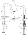
- Fig. 1 shows in a z. T. cut front view Rollover protection system with a tubular rollover body 1, the two adjacent vehicle seats spanned, i.e. on Rollover protection system, which is assigned to a pair of vehicle seats, at which the invention is preferably applied.
- the invention can also be used in the cassette systems described at the beginning, which are each individually assigned to a vehicle seat.
- the tubular rollover body consists of a meandering curve Base tube 2, each with a leg tube 3, 4 at both ends is connected, in particular by welding.
- the base tube 2 has two upstanding sections 2 a, 2 b, about which the vehicle in the event of a Rollover would roll, and each at the height of the vehicle seat are attached, as well as a central, lowered section 2 c, on which a Holding member 5 is attached, which will be explained later.
- the rollover protection system also has a traverse 6, which Guide blocks 6 a, 6 b, in which the leg tubes 3, 4 are guided, is connected to the vehicle.
- a traverse 6 On the cross member 6 is also a common one sensor-controlled trigger system 7 firmly attached, in particular a Release magnet with a double lever pawl for the releasable Active engagement with the holding member 5 on the roll body 1, as in the DE 197 50 693 A1 is described.
- the trigger system 7 in connection with the holding member 5 form the holding device for the Holding the rollover body 1 in the retracted state, wherein in Fig. 1 the triggered state is shown, in which the roll body 1 in the upper, protective position.
- a drive compression spring 8 recorded, which are each at the bottom of a stop 9 of a rest column 10, supports, which in turn via a foot part 11 with the vehicle floor 12 (Fig. 2) is firmly connected, e.g., as shown, via screw connections 13.
- the upper end of the drive compression spring 8 is supported in a known manner on the Connection point of the base tube 2 with the leg tubes 3, 4.
- the Stop 9 serves at the same time to guide the lower leg tubes 3, 4 and is designed according to this function, i.e. has a thickness that sufficient guiding surface in connection with the Plain bearing bush 14 a in Fig. 4th
- the locking pillars 10 serve once as the lower guide for the leg tubes 3, 4 in addition to the upper guide through the guide blocks 6 a, 6 b and form on the other hand by molded on them, rack-like locking lugs 10 a the locking element of the vehicle locking device described at the beginning, i.e. the re-entry lock for the extended roll body 1.
- the locking lugs 10 a can be in one piece be integrally formed on the rest column 10. But you can also by separate, at strips attached to the base body of the rest column can be realized.
- the movable locking element together with the roll bar 1 Re-entry lock which in the prior art is typically a Pawl is formed, consists essentially of in the case of the invention a housing 14 with two opposite paving stones 15 and two Springs, preferably leaf springs 16.
- the locking blocks 15 are horizontally slidably mounted in the housing 14 and are pressed by the leaf springs 16 against the center of the housing.
- the paving stones 15 have a slope of 3 ° - 5 ° on the lower contact surface. This causes in the load case, i.e. if a force acts on the roll bar that the Barrier blocks 15 do not slide out of the housing 14, but into the latches Press 10 a of the rest column 10, and so in the desired manner Form re-entry lock.
- the pawls 15 are namely in the extended state of the Rollover body, which is shown in Fig. 2, always in engagement with the Lugs 10, except for the intended reversal of the roll bar 1 in the idle state, wherein in Fig. 2, the position of the housing 14 with the Barrier stones 15 is additionally shown in the idle state.
- a re-entry movement is due to the intervention of the Locking blocks 15 locked in the locking lugs 10 a of the locking column 10.
- both the locking column 10th and the locking lugs 10 a and the housing 14 with the pawls 15 as Metal parts are formed and are preferably made of steel.
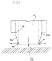
- the blocking stones 15 have lateral arms or noses 18 which protrude from the housing 14. It is also an unlocking element 17 in Form of a plastic slider provided, which is shown in Fig. 6 in more detail is. It has laterally attached bevels 17 a tapering downwards, which each have a small undercut 17 b at their upper, broad base have that prevent the pawls 15 from locking unintentionally.
- the Plastic slide 17 is, as shown in Fig. 5, in guides 19, 20 slidably supported.
- the slide 17 is pressed manually until the arms 18 in each case engage the undercut 17 b.
- the bevels 17 a Noses or arms 18 pushed outwards in the direction of the arrow.
- the locking blocks 15 out of engagement with the locking lugs 10 a and the locking is reserved for reversing.
- the roll bar 2 can be manually operated with both hands (the release has been inserted through the undercut in self-holding). He reaches together with the slide 17, the lower position, predetermined by the in Fig. 6 symbolically shown stop 22 is by the Insertion movement of the slide 17 pushed up in response. The Arms 18 jump out of the undercuts 17 b and the paving stones lock the roll bar again.
- a stop 21 in the housing limits the movement of the Roll bar as soon as the stop on the underside of the guide body 9 the rest column 10 strikes (Fig. 2).
Landscapes
- Engineering & Computer Science (AREA)
- Mechanical Engineering (AREA)
- Refuge Islands, Traffic Blockers, Or Guard Fence (AREA)
- Fittings On The Vehicle Exterior For Carrying Loads, And Devices For Holding Or Mounting Articles (AREA)
- Body Structure For Vehicles (AREA)
Abstract
Description
- einem geführten Überrollkörper, der im Normalzustand gegen die Kraft von mindestens einer vorgespannten Antriebs-Druckfeder durch eine Haltevorrichtung in einer unteren, eingefahrenen Ruhelage haltbar ist, und unter Lösen der Haltevorrichtung durch die Federkraft der Antriebs-Druckfeder in eine obere, schützende Stellung bringbar ist, und
- einer Verriegelungseinrichtung für das Verriegeln des Überrollkörpers in der oberen Stellung, bestehend aus zwei Verriegelungskomponenten, von denen eine fahrzeugfest angebracht und die andere mit dem Überrollkörper verbunden ist, und die Rastelemente besitzen, die in der ausgefahrenen Stellung des Überrollkörpers im verriegelnden Wirkeingriff stehen, wobei an zwei, quer zur Verfahrrichtung des Überrollkörpers beabstandeten, Stellen des Überrollkörpers leistenartige Rastelemente vorgesehen sind, die sich in Verfahrrichtung des Überrollkörpers erstrecken, und eine Komponente der Verriegelungseinrichtung bilden.
- einem geführten Überrollkörper, der im Normalzustand gegen die Kraft von mindestens einer vorgespannten Antriebs-Druckfeder durch eine Haltevorrichtung in einer unteren, eingefahrenen Ruhelage haltbar ist, und unter Lösen der Haltevorrichtung durch die Federkraft der Antriebs-Druckfeder in eine obere, schützende Stellung bringbar ist, und
- einer Verriegelungseinrichtung für das Verriegeln des Überrollkörpers in der oberen Stellung, bestehend aus zwei Verriegelungskomponenten, von denen eine fahrzeugfest angebracht und die andere mit dem Überrollkörper verbunden ist, und die Rastelemente besitzen, die in der ausgefahrenen Stellung des Überrollkörpers im verriegelnden Wirkeingriff stehen, wobei an zwei, quer zur Verfahrrichtung des Überrollkörpers beabstandeten, Stellen des Überrollkörpers leistenartige Rastelemente vorgesehen sind, die sich in Verfahrrichtung des Überrollkörpers erstrecken, und eine Komponente der Verriegelungseinrichtung bilden, gemäß der Erfindung dadurch, daß an jeder beabstandeten Stelle des Überrollkörpers jeweils mindestens ein Paar gegenüberliegender, leistenartiger Rastelemente vorgesehen ist, und daß die zweite Komponente der Verriegelungseinrichtung an jeder besagten Stelle des Überrollbügels durch mindestens ein Paar von Sperrsteinen gebildet ist, die gegenüberliegend in einem Gehäuse in Front zu den zugeordneten leistenartigen Rastelementen gegen die Kraft einer Feder radial verschiebbar gehaltert sind und mindestens eine Rastnase für den verriegelnden Wirkeingriff mit dem zugeordneten leistenartigen Rastelement besitzen.
- Störung des Kraftflusses, bei der Ableitung der Kräfte in das Fahrzeug durch die Verriegelung
- kein symmetrischer, gleichmäßiger Wirkeingriff der Verriegelungskomponenten, sondern, bedingt durch die Drehbewegung der Klinke, ein ungleichmäßiger, und auch einseitiger Wirkeingriff.
- Fig. 1
- in einer zum Teil geschnittenen Frontansicht ein Überrollschutzsystem mit einem rohrförmigen Überrollkörper, der zwei nebeneinander liegende Fahrzeugsitze überspannt, bei dem die erfindungsgemäße Verriegelungseinrichtung, hier bestehend aus fahrzeugfesten Rastsäulen und mit dem Überrollkörper bewegten, in einem Gehäuse radial beweglich aufgenommenen Sperrsteinen, bevorzugt Anwendung findet,
- Fig. 2
- einem Ausschnitt aus Fig. 1 in Form eines schematischen Längsschnittes eine nähere Darstellung der Rastsäulen und der Sperrsteine sowie deren Zusammenwirken,
- Fig. 3
- einen Ausschnitt entsprechend Fig. 2, jedoch in einer z. T. weggebrochenen isometrischen Darstellung,
- Fig. 4
- einen vergrößerten Ausschnitt aus Fig. 4 unter näherer Darstellung des Wirkeingriffes der Sperrsteine mit den Rastnasen der Rastsäulen,
- Fig. 5
- eine isometrische Darstellung des die Sperrsteine aufnehmenden Gehäuses, und
- Fig. 6
- in einer schematischen Darstellung einen Schieber zur manuellen Entriegelung der Sperrsteine.
Claims (12)
- Überrollschutzsystem für Kraftfährzeuge, mitdadurch gekennzeichnet, daß an jeder beabstandeten Stelle des Überrollkörpers (1) jeweils mindestens ein Paar gegenüberliegender, leistenartiger Rastelemente (10a) vorgesehen ist, und daß die zweite Komponente der Verriegelungseinrichtung an jeder besagten Stelle des Überrollbügels durch mindestens ein Paar von Sperrsteinen (15) gebildet ist, die gegenüberliegend in einem Gehäuse (14) in Front zu den zugeordneten leistenartigen Rastelementen ( 10 a) gegen die Kraft einer Feder (16) radial verschiebbar gehaltert sind und mindestens eine Rastnase für den verriegelnden Wirkeingriff mit dem zugeordneten leistenartigen Rastelement (10 a) besitzen.einem geführten Überrollkörper (1), der im Normalzustand gegen die Kraft von mindestens einer vorgespannten Antriebs-Druckfeder (8) durch eine Haltevorrichtung (5, 7) in einer unteren, eingefahrenen Ruhelage haltbar ist, und unter Lösen der Haltevorrichtung durch die Federkraft der Antriebs-Druckfeder (8) in eine obere, schützende Stellung bringbar ist, undeiner Verriegelungseinrichtung für das Verriegeln des Überrollkörpers (1) in der oberen Stellung, bestehend aus zwei Verriegelungskomponenten, von denen eine fahrzeugfest angebracht und die andere mit dem Überrollkörper (1) verbunden ist, und die Rastelemente besitzen, die in der ausgefahrenen Stellung des Überrollkörpers (1) im verriegelnden Wirkeingriff stehen, wobei an zwei, quer zur Verfahrrichtung des Überrollkörpers (1) beabstandeten, Stellen des Überrollkörpers (1) leistenartige Rastelemente (10 a) vorgesehen sind, die sich in Verfahrrichtung des Überrollkörpers (1) erstrecken, und eine Komponente der Verriegelungseinrichtung bilden,
- Überrollschutzsystem nach Anspruch 1, dadurch gekennzeichnet, daß jeder Sperrstein (15) zwei Rastnasen hat.
- Überrollschutzsystem nach Anspruch 1 oder 2, dadurch gekennzeichnet, daß die Rastnasen an der unteren Kontaktfläche eine Schräge, vorzugsweise im Bereich von 3° - 5°, aufweisen.
- Überrollschutzsystem nach einem der Ansprüche 1 bis 3, dadurch gekennzeichnet, daß die die Sperrsteine (15) radial vorspannenden Federn (16) durch Blattfedern gebildet sind.
- Überrollschutzsystem nach einem der Ansprüche 1 bis 4, dadurch gekennzeichnet, daß die leistenartigen Rastelemente (10 a) an einem fahrzeugfesten Führungsteil (10) des Überrollkörpers (1) vorgesehen sind und die Gehäuse (14) mit den Sperrsteinen (15) am Überrollkörper (1) angebracht sind.
- Überrollschutzsystem nach Anspruch 5, mit einem rohrförmigen Überrollbügel (2), bestehend aus zwei parallelen Schenkelrohren (3, 4) und einem diese verbindenden Basisschenkel (2 a - 2 c), dadurch gekennzeichnet, daß das Führungsteil für jedes Schenkelrohr (3, 4) eine Rastsäule (10) ist, die am Fahrzeugboden (12) befestigt ist, im oberen Bereich an zwei gegenüberliegenden Stellen jeweils leistenartige Rastelemente (10 a) aufweist und kopfseitig einen Führungskörper (9) für das zugehörige, die Rastsäule umfassende Schenkelrohr (3, 4) besitzt, der zugleich die Abstützung für das untere Ende der Antriebs-Druckfeder (8) bildet, deren oberes Ende sich an einem Gegenlager im Schenkelrohr (3, 4) abstützt, und daß das Gehäuse (14) mit den Sperrsteinen (15) jeweils am offenen Ende des zugehörigen Schenkelrohres (3, 4) angebracht ist.
- Überrollschutzsystem nach Anspruch 6, dadurch gekennzeichnet, daß in dem Gehäuse (14) ein Anschlag (21) ausgebildet ist, der einen Gegenanschlag für den Führungskörper (9) bildet.
- Überrollschutzsystem nach einem der Ansprüche 1 bis 7, dadurch gekennzeichnet, daß die Sperrsteine (15) aus dem Gehäuse (14) herausragende Nasen (18) besitzen, über die die Sperrsteine (15) mittels eines entriegelnden Schiebers (17) manuell außer Wirkeingriff mit den zahnleistenartigen Rastelementen (10 a) bringbar sind.
- Überrollschutzsystem nach Anspruch 8, dadurch gekennzeichnet, daß der Schieber (17) im Bereich der Sperrsteine (15) Schrägen (17 a) und an der oberen, breiten Basis Hinterschnitte (17 b) für ein Einrasten der Nasen (18) besitzt.
- Überrollschutzsystem nach einem der Ansprüche 6 bis 9, dadurch gekennzeichnet, daß der rohrförmige Überrollbügel (2) so ausgebildet ist, daß er zwei nebeneinander liegende Fahrzeugsitze überspannt und die Rastsäulen (10) entsprechend beabstandet am Fahrzeugboden (12) angebracht sind.
- Überrollschutzsystem nach Anspruch 10, dadurch gekennzeichnet, daß eine die Bügelbreite überspannende, fahrzeugfest angebrachte, Traverse (6) vorgesehen ist, die jeweils einen Führungsblock (6 a, 6 b) für die geführte Aufnahme des zugehörigen Schenkelrohres (3, 4) aufweist.
- Überrollschutzsystem nach Anspruch 11, dadurch gekennzeichnet, daß an der Traverse (6) ein sensorgesteuertes Auslösesystem (7) und an einem mittig abgesenkten Abschnitt (2 c) des Überrollbügels (2) ein Halteglied (5) angebracht ist, das in lösbaren Wirkeingriff mit dem Auslösesystem (7) bringbar ist.
Applications Claiming Priority (2)
| Application Number | Priority Date | Filing Date | Title |
|---|---|---|---|
| DE2000144930 DE10044930C1 (de) | 2000-09-12 | 2000-09-12 | Überrollschutzsystem für Kraftfahrzeuge |
| DE10044930 | 2000-09-12 |
Publications (4)
| Publication Number | Publication Date |
|---|---|
| EP1186481A2 true EP1186481A2 (de) | 2002-03-13 |
| EP1186481A3 EP1186481A3 (de) | 2006-02-01 |
| EP1186481B1 EP1186481B1 (de) | 2006-12-13 |
| EP1186481B8 EP1186481B8 (de) | 2007-02-14 |
Family
ID=7655842
Family Applications (1)
| Application Number | Title | Priority Date | Filing Date |
|---|---|---|---|
| EP20010118213 Expired - Lifetime EP1186481B8 (de) | 2000-09-12 | 2001-07-28 | Überrollschutzsystem für Kraftfahrzeuge |
Country Status (2)
| Country | Link |
|---|---|
| EP (1) | EP1186481B8 (de) |
| DE (2) | DE10044930C1 (de) |
Cited By (8)
| Publication number | Priority date | Publication date | Assignee | Title |
|---|---|---|---|---|
| WO2004005083A1 (de) * | 2002-07-02 | 2004-01-15 | Ise Innomotive Systems Europe Gmbh | Überrollschutzsystem für kraftfahrzeuge |
| WO2004094197A1 (de) * | 2003-04-24 | 2004-11-04 | Wilhelm Karmann Gmbh | Überrollschutz-vorrichtung für ein kraftfahrzeug |
| FR2871758A1 (fr) * | 2004-07-02 | 2005-12-23 | France Design Sa | Dispositif de securite en cas de retournement d'un vehicule |
| FR2873072A1 (fr) * | 2004-07-02 | 2006-01-20 | France Design Sa | Dispositif de securite en cas de retournement d'un vehicule |
| EP1842736A1 (de) * | 2006-04-04 | 2007-10-10 | Automotive Group ISE Innomotive Systems Europe GmbH | Überrollschutzsystem für Kraftfahrzeuge mit mindestens einem aktiv aufstellbaren Überrollbügel |
| US7341278B2 (en) | 2004-06-21 | 2008-03-11 | Heuliez | Safety device used in case a vehicle rolls over |
| US7540535B2 (en) * | 2005-06-22 | 2009-06-02 | Wilhelm Karmann Gmbh | Modular unit for a convertible |
| EP2394867A1 (de) * | 2011-05-03 | 2011-12-14 | ISE Automotive GmbH | Überrollschutzsystem für Kraftfahrzeuge |
Families Citing this family (13)
| Publication number | Priority date | Publication date | Assignee | Title |
|---|---|---|---|---|
| DE102004016362B4 (de) * | 2003-04-10 | 2020-12-03 | Bayerische Motoren Werke Aktiengesellschaft | Baueinheit für ein Cabriolet |
| JP4560521B2 (ja) | 2004-02-18 | 2010-10-13 | バイエリッシェ モートーレン ウエルケ アクチエンゲゼルシャフト | 車両のボディ |
| DE102006001579B3 (de) * | 2006-01-12 | 2007-03-01 | Ise Innomotive Systems Europe Gmbh | Überrollschutzsystem für Kraftfahrzeuge mit einem aktiv aufstellbaren Überrollbügel |
| DE102006002941A1 (de) * | 2006-01-21 | 2007-08-02 | Automotive Group Ise Innomotive Systems Europe Gmbh | Überrollschutzsystem für Kraftfahrzeuge mit einem Überrollbügel |
| DE102006006658B3 (de) * | 2006-02-14 | 2007-05-03 | Automotive Group Ise Innomotive Systems Europe Gmbh | Überrollschutzsystem für Kraftfahrzeuge mit einem aktiv aufstellbaren, einen Verschleissschutz aufweisenden Überrollbügel |
| DE102006006659B3 (de) * | 2006-02-14 | 2007-06-21 | Automotive Group Ise Innomotive Systems Europe Gmbh | Überrollschutzsystem für Kraftfahrzeuge mit einem annähernd fahrzeugbreiten aktiv aufstellbaren Überrollbügel |
| EP1991447B1 (de) | 2006-02-27 | 2013-06-19 | Benteler Automobiltechnik GmbH | Unfallschutzsystem für ein fahrzeug und verfahren zur freigabe und erweiterung eines unfallschutzsystems für ein fahrzeug |
| DE102006023502B3 (de) | 2006-05-18 | 2008-02-07 | Automotive Group Ise Innomotive Systems Europe Gmbh | Überrollschutzsystem für Kraftfahrzeuge mit mindestens einem aktiv aufstellbaren Überrollkörper |
| DE102006024332B3 (de) * | 2006-05-24 | 2008-01-31 | Automotive Group Ise Innomotive Systems Europe Gmbh | Überrollschutzsystem und Kraftfahrzeuge mit mindestens einem aktiv aufstellbaren Überrollkörper |
| DE102006038757A1 (de) * | 2006-08-17 | 2008-02-28 | Automotive Group Ise Innomotive Systems Europe Gmbh | Überrollschutzsystem für Kraftfahrzeuge mit mindestens einem Überrollbügel |
| DE102006048085B4 (de) * | 2006-10-10 | 2009-05-07 | Ise Automotive Gmbh | Überrollschutzsystem für Kraftfahrzeuge mit mindestens einem aktiv aufstellbaren Überrollbügel |
| DE102006055491B4 (de) * | 2006-11-24 | 2009-06-18 | Ise Automotive Gmbh | Überrollschutzsystem eines Kraftfahrzeugs mit einem mittig angeordneten aufstellbaren Überrollkörper |
| DE102007005517B4 (de) | 2007-02-03 | 2010-09-30 | Ise Automotive Gmbh | Überrollschutzsystem für Kraftfahrzeuge mit einem aktiv aufstellbaren Überrollkörper mit integriertem Deformationselement |
Citations (3)
| Publication number | Priority date | Publication date | Assignee | Title |
|---|---|---|---|---|
| DE4100506C1 (de) | 1991-01-10 | 1992-05-21 | Mercedes-Benz Aktiengesellschaft, 7000 Stuttgart, De | |
| DE4342400A1 (de) | 1993-08-03 | 1995-02-09 | Teves Gmbh Alfred | Überrollbügeleinrichtung mit Innenführung und Außenführung |
| DE19781833T1 (de) | 1996-06-18 | 1999-06-17 | Norsk Hydro As | Überrolleinrichtung für ein Fahrzeug |
Family Cites Families (2)
| Publication number | Priority date | Publication date | Assignee | Title |
|---|---|---|---|---|
| DE19712955B4 (de) * | 1997-03-27 | 2011-03-10 | Bayerische Motoren Werke Aktiengesellschaft | Überrollschutzsystem für ein Fahrzeug, insbesondere für ein Cabriolet |
| DE19952125C1 (de) * | 1999-10-29 | 2001-02-08 | Ise Gmbh | Überrollschutzsystem für Kraftfahrzeuge |
-
2000
- 2000-09-12 DE DE2000144930 patent/DE10044930C1/de not_active Expired - Fee Related
-
2001
- 2001-07-28 EP EP20010118213 patent/EP1186481B8/de not_active Expired - Lifetime
- 2001-07-28 DE DE50111621T patent/DE50111621D1/de not_active Expired - Lifetime
Patent Citations (3)
| Publication number | Priority date | Publication date | Assignee | Title |
|---|---|---|---|---|
| DE4100506C1 (de) | 1991-01-10 | 1992-05-21 | Mercedes-Benz Aktiengesellschaft, 7000 Stuttgart, De | |
| DE4342400A1 (de) | 1993-08-03 | 1995-02-09 | Teves Gmbh Alfred | Überrollbügeleinrichtung mit Innenführung und Außenführung |
| DE19781833T1 (de) | 1996-06-18 | 1999-06-17 | Norsk Hydro As | Überrolleinrichtung für ein Fahrzeug |
Cited By (9)
| Publication number | Priority date | Publication date | Assignee | Title |
|---|---|---|---|---|
| WO2004005083A1 (de) * | 2002-07-02 | 2004-01-15 | Ise Innomotive Systems Europe Gmbh | Überrollschutzsystem für kraftfahrzeuge |
| WO2004094197A1 (de) * | 2003-04-24 | 2004-11-04 | Wilhelm Karmann Gmbh | Überrollschutz-vorrichtung für ein kraftfahrzeug |
| US7481458B2 (en) | 2003-04-24 | 2009-01-27 | Wilhelm Karmann Gmbh | Roll-over protection device for a motor vehicle |
| US7341278B2 (en) | 2004-06-21 | 2008-03-11 | Heuliez | Safety device used in case a vehicle rolls over |
| FR2871758A1 (fr) * | 2004-07-02 | 2005-12-23 | France Design Sa | Dispositif de securite en cas de retournement d'un vehicule |
| FR2873072A1 (fr) * | 2004-07-02 | 2006-01-20 | France Design Sa | Dispositif de securite en cas de retournement d'un vehicule |
| US7540535B2 (en) * | 2005-06-22 | 2009-06-02 | Wilhelm Karmann Gmbh | Modular unit for a convertible |
| EP1842736A1 (de) * | 2006-04-04 | 2007-10-10 | Automotive Group ISE Innomotive Systems Europe GmbH | Überrollschutzsystem für Kraftfahrzeuge mit mindestens einem aktiv aufstellbaren Überrollbügel |
| EP2394867A1 (de) * | 2011-05-03 | 2011-12-14 | ISE Automotive GmbH | Überrollschutzsystem für Kraftfahrzeuge |
Also Published As
| Publication number | Publication date |
|---|---|
| DE10044930C1 (de) | 2002-03-28 |
| EP1186481B1 (de) | 2006-12-13 |
| DE50111621D1 (de) | 2007-01-25 |
| EP1186481A3 (de) | 2006-02-01 |
| EP1186481B8 (de) | 2007-02-14 |
Similar Documents
| Publication | Publication Date | Title |
|---|---|---|
| DE10044930C1 (de) | Überrollschutzsystem für Kraftfahrzeuge | |
| DE4345524C2 (de) | Überrollschutzsystem | |
| EP1359059B1 (de) | Überrollschutzsystem für Kraftfahrzeuge mit einer selbsthaltenden Entriegelungseinrichtung | |
| DE19906912C1 (de) | Überroll-Schutzsystem für Kraftfahrzeuge | |
| DE102012221398B4 (de) | Aufnahmevorrichtung für wenigstens ein Becher- oder Flaschenbehältnis | |
| DE102013222651B4 (de) | Vorrichtung zum Sichern von Ladegut in einem Laderaum sowie Befestigungselement hierfür | |
| DE4342400A1 (de) | Überrollbügeleinrichtung mit Innenführung und Außenführung | |
| DE102004006873B3 (de) | Kraftfahrzeugsitz | |
| EP0916552B1 (de) | Ausfahrbarer Überrollbügel für Kraftfahrzeuge | |
| EP1095823B1 (de) | Überrollschutzsystem für Kraftfahrzeuge | |
| DE4425954C1 (de) | Überrrollbügel für ein mit einem versenkbaren Dach versehenes Cabriolet | |
| DE102006028664B4 (de) | Überrollschutzsystem für ein Kraftfahrzeug | |
| DE10229635C1 (de) | Überrollschutzsystem für Kraftfahrzeuge | |
| DE10103247C1 (de) | Überrollschutzsystem für Kraftfahrzeuge | |
| DE202021100671U1 (de) | Kopfstütze | |
| DE10044927C1 (de) | Überrollschutzsystem für Kraftfahrzeuge | |
| EP0623492B2 (de) | Überrollschutz-Vorrichtung für ein Kraftfahrzeug | |
| DE19532276C2 (de) | Laderaumabdeckung für einen Kombi-Personenkraftwagen | |
| DE10044929C1 (de) | Überrollschutzsystem | |
| DE60301149T2 (de) | Faltbarer Tischtennistisch | |
| DE10346402B3 (de) | Überrollschutzsystem für Kraftfahrzeuge, das einen ausfahrbaren Überrollkörper mit kombinierter Kopfstütze aufweist | |
| EP1227012B1 (de) | Überrollschutzsystem für Kraftfahrzeuge | |
| EP1034987B1 (de) | Überroll-Schutzvorrichtung fÜr Kraftfahrzeuge | |
| DE102015105221B4 (de) | Überrollschutzsystem für Kraftfahrzeuge | |
| DE10103245C1 (de) | Überrollschutzsystem für Kraftfahrzeuge |
Legal Events
| Date | Code | Title | Description |
|---|---|---|---|
| PUAI | Public reference made under article 153(3) epc to a published international application that has entered the european phase |
Free format text: ORIGINAL CODE: 0009012 |
|
| AK | Designated contracting states |
Kind code of ref document: A2 Designated state(s): AT BE CH CY DE DK ES FI FR GB GR IE IT LI LU MC NL PT SE TR |
|
| AX | Request for extension of the european patent |
Free format text: AL;LT;LV;MK;RO;SI |
|
| PUAL | Search report despatched |
Free format text: ORIGINAL CODE: 0009013 |
|
| AK | Designated contracting states |
Kind code of ref document: A3 Designated state(s): AT BE CH CY DE DK ES FI FR GB GR IE IT LI LU MC NL PT SE TR |
|
| AX | Request for extension of the european patent |
Extension state: AL LT LV MK RO SI |
|
| 17P | Request for examination filed |
Effective date: 20060314 |
|
| GRAP | Despatch of communication of intention to grant a patent |
Free format text: ORIGINAL CODE: EPIDOSNIGR1 |
|
| GRAS | Grant fee paid |
Free format text: ORIGINAL CODE: EPIDOSNIGR3 |
|
| AKX | Designation fees paid |
Designated state(s): DE FR GB IT |
|
| GRAA | (expected) grant |
Free format text: ORIGINAL CODE: 0009210 |
|
| AK | Designated contracting states |
Kind code of ref document: B1 Designated state(s): DE FR GB IT |
|
| REG | Reference to a national code |
Ref country code: GB Ref legal event code: FG4D Free format text: NOT ENGLISH |
|
| RBV | Designated contracting states (corrected) |
Designated state(s): FR GB IT |
|
| REF | Corresponds to: |
Ref document number: 50111621 Country of ref document: DE Date of ref document: 20070125 Kind code of ref document: P |
|
| GBT | Gb: translation of ep patent filed (gb section 77(6)(a)/1977) |
Effective date: 20070321 |
|
| ET | Fr: translation filed | ||
| PLBE | No opposition filed within time limit |
Free format text: ORIGINAL CODE: 0009261 |
|
| STAA | Information on the status of an ep patent application or granted ep patent |
Free format text: STATUS: NO OPPOSITION FILED WITHIN TIME LIMIT |
|
| 26N | No opposition filed |
Effective date: 20070914 |
|
| PGFP | Annual fee paid to national office [announced via postgrant information from national office to epo] |
Ref country code: FR Payment date: 20080718 Year of fee payment: 8 Ref country code: IT Payment date: 20080726 Year of fee payment: 8 |
|
| PGFP | Annual fee paid to national office [announced via postgrant information from national office to epo] |
Ref country code: GB Payment date: 20080723 Year of fee payment: 8 |
|
| GBPC | Gb: european patent ceased through non-payment of renewal fee |
Effective date: 20090728 |
|
| REG | Reference to a national code |
Ref country code: FR Ref legal event code: ST Effective date: 20100331 |
|
| PG25 | Lapsed in a contracting state [announced via postgrant information from national office to epo] |
Ref country code: FR Free format text: LAPSE BECAUSE OF NON-PAYMENT OF DUE FEES Effective date: 20090731 |
|
| PG25 | Lapsed in a contracting state [announced via postgrant information from national office to epo] |
Ref country code: GB Free format text: LAPSE BECAUSE OF NON-PAYMENT OF DUE FEES Effective date: 20090728 |
|
| PG25 | Lapsed in a contracting state [announced via postgrant information from national office to epo] |
Ref country code: IT Free format text: LAPSE BECAUSE OF NON-PAYMENT OF DUE FEES Effective date: 20090728 |