EP1186476A2 - Electrical power supply system for a vehicle - Google Patents
Electrical power supply system for a vehicle Download PDFInfo
- Publication number
- EP1186476A2 EP1186476A2 EP01104499A EP01104499A EP1186476A2 EP 1186476 A2 EP1186476 A2 EP 1186476A2 EP 01104499 A EP01104499 A EP 01104499A EP 01104499 A EP01104499 A EP 01104499A EP 1186476 A2 EP1186476 A2 EP 1186476A2
- Authority
- EP
- European Patent Office
- Prior art keywords
- alternator
- voltage
- battery
- supply system
- power supply
- Prior art date
- Legal status (The legal status is an assumption and is not a legal conclusion. Google has not performed a legal analysis and makes no representation as to the accuracy of the status listed.)
- Granted
Links
Images


Classifications
-
- H—ELECTRICITY
- H02—GENERATION; CONVERSION OR DISTRIBUTION OF ELECTRIC POWER
- H02J—CIRCUIT ARRANGEMENTS OR SYSTEMS FOR SUPPLYING OR DISTRIBUTING ELECTRIC POWER; SYSTEMS FOR STORING ELECTRIC ENERGY
- H02J7/00—Circuit arrangements for charging or depolarising batteries or for supplying loads from batteries
- H02J7/14—Circuit arrangements for charging or depolarising batteries or for supplying loads from batteries for charging batteries from dynamo-electric generators driven at varying speed, e.g. on vehicle
- H02J7/16—Regulation of the charging current or voltage by variation of field
- H02J7/163—Regulation of the charging current or voltage by variation of field with special means for initiating or limiting the excitation current
-
- H—ELECTRICITY
- H02—GENERATION; CONVERSION OR DISTRIBUTION OF ELECTRIC POWER
- H02J—CIRCUIT ARRANGEMENTS OR SYSTEMS FOR SUPPLYING OR DISTRIBUTING ELECTRIC POWER; SYSTEMS FOR STORING ELECTRIC ENERGY
- H02J7/00—Circuit arrangements for charging or depolarising batteries or for supplying loads from batteries
- H02J7/14—Circuit arrangements for charging or depolarising batteries or for supplying loads from batteries for charging batteries from dynamo-electric generators driven at varying speed, e.g. on vehicle
- H02J7/16—Regulation of the charging current or voltage by variation of field
-
- H—ELECTRICITY
- H02—GENERATION; CONVERSION OR DISTRIBUTION OF ELECTRIC POWER
- H02J—CIRCUIT ARRANGEMENTS OR SYSTEMS FOR SUPPLYING OR DISTRIBUTING ELECTRIC POWER; SYSTEMS FOR STORING ELECTRIC ENERGY
- H02J7/00—Circuit arrangements for charging or depolarising batteries or for supplying loads from batteries
- H02J7/14—Circuit arrangements for charging or depolarising batteries or for supplying loads from batteries for charging batteries from dynamo-electric generators driven at varying speed, e.g. on vehicle
- H02J7/1438—Circuit arrangements for charging or depolarising batteries or for supplying loads from batteries for charging batteries from dynamo-electric generators driven at varying speed, e.g. on vehicle in combination with power supplies for loads other than batteries
-
- Y—GENERAL TAGGING OF NEW TECHNOLOGICAL DEVELOPMENTS; GENERAL TAGGING OF CROSS-SECTIONAL TECHNOLOGIES SPANNING OVER SEVERAL SECTIONS OF THE IPC; TECHNICAL SUBJECTS COVERED BY FORMER USPC CROSS-REFERENCE ART COLLECTIONS [XRACs] AND DIGESTS
- Y02—TECHNOLOGIES OR APPLICATIONS FOR MITIGATION OR ADAPTATION AGAINST CLIMATE CHANGE
- Y02T—CLIMATE CHANGE MITIGATION TECHNOLOGIES RELATED TO TRANSPORTATION
- Y02T10/00—Road transport of goods or passengers
- Y02T10/60—Other road transportation technologies with climate change mitigation effect
- Y02T10/70—Energy storage systems for electromobility, e.g. batteries
Definitions
- the present invention relates to an electrical power supply system and more particularly to an electrical power supply system for an automotive vehicle for supplying power to a high power load for a short time period by increasing an alternator output.
- a 3 ⁇ phase alternator is driven by an oil pressure pump and an oil pressure motor laden in a vehicle, and an output frequency as well as a voltage of the alternator is kept constant by keeping a constant engine rotation after the engine is started.
- a high voltage of the alternator with a high generating efficiency could be applied to the high power load and a battery through a stepping ⁇ down voltage converter.
- a rated output of the alternator regardless of an engine rotating speed is obtained from an idling zone, and the alternator with a small size and a light weight is capable of supplying power to a high power with high voltage load.
- the alternator is also able to supply the required power to a low voltage load through an AC/DC voltage converter. Furthermore, a layout freedom of the alternator driven by an oil pressure is not limited but even enlarged, as the AC/DC voltage converter operating with a constant output frequency of the alternator can be small in size and light in weight.
- an electrical power supply system for an automotive vehicle capable of supplying a required power to both a high power load and a battery.
- an electrical power supply system for the automotive vehicle comprises:
- the electrical power supply system for the automotive vehicle wherein a voltage applied to the field coil is stepped up to a voltage of the battery multiplied by a factor of 1.2 to 2.0.
- the electrical power supply system for the automotive vehicle wherein the output voltage of the alternator changing in response to the rotating speed is set to be higher than the voltage of the battery.
- the electrical power supply system for the automotive vehicle wherein the output voltage of the alternator changes in response to the rotating speed detected by a rotating speed detector.
- the electrical power supply system for the automotive vehicle wherein the field current of the alternator is controlled by a detected temperature of the field coil by a temperature sensing device in the voltage control means.
- the electrical power supply system for the automotive vehicle wherein the field current of the alternator is controlled by an inferred temperature from the field current of the alternator detected by a current detecting device in the voltage control means.
- the electrical power supply system for the automotive vehicle wherein the stepping ⁇ up DC/DC converter for applying the stepped up voltage of the battery to the field coil is integrated the voltage control means.
- an electrical power supply system for an automotive vehicle comprising:
- the electrical power supply system for the automotive vehicle wherein the stepping ⁇ down DC/DC converter for supplying the power to both the high power load and the battery is integrated with the voltage control means.
- the electrical power supply system for the automotive vehicle wherein an output voltage of the stepping ⁇ down DC/DC converter has a negative gradient temperature characteristics.
- the alternator output is increased by stepping up the field voltage.
- the maximum alternator output is obtained by controlling the output voltage to change responding to the rotating speed of the alternator.
- the alternator output is controlled by detecting the temperature. Therefore, the conventional type alternator is applicable for supplying adequate power to both the high power load and the battery.
- the stable maximum output power of the alternator during idling up operation of the internal combustion engine is obtainable as the output voltage is subjected to the rotating speed of the alternator.
- the reliable , inexpensive and small ⁇ sized power supply system is realized by avoiding sophistication of a control system,
- Fig. 1 is a schematic diagram of a power supply system for an automotive vehicle according to an embodiment 1 of the present invention.
- Fig. 2 is a graph representing characteristics of the power supply system for the automotive vehicle for explaining operation in the embodiment 1 of the present invention.
- Fig. 3 is a graph representing characteristics of the power supply system for the automotive vehicle for explaining operation in the embodiment 1 of the present invention.
- Fig. 4 is a schematic diagram of the power supply system for the automotive vehicle according to an embodiment 2 of the present invention.
- Fig. 1 is a circuit diagram of an electrical power supply system according to an embodiment 1 of the present invention.
- Fig.2 is a graph representing output characteristics of an alternator for a field voltage of a 3 ⁇ phase alternator on a vehicle according to the present invention.
- Fig .3 is a graph representing output characteristics of the alternator for a rotating speed according to the present invention in case a field current is set to a predetermined value.
- the alternator is, for example, a 3 ⁇ phase alternator 1 on a vehicle comprising an armature constructive assembly 2 including an armature winding for generating a 3 ⁇ phase AC power and a 3 ⁇ phase full wave rectifier for rectifying the 3 ⁇ phase AC power, a field coil 3 for providing a magnetic flux to the armature winding, and a regulator 4 as a voltage control means for controlling a field current of the field coil 3.
- a battery 5 is a vehicle ⁇ laden secondary battery.
- a stepping ⁇ up DC/DC converter 6 is for stepping up a voltage of a battery 5 to apply to the field coil 3, and the battery 5 is charged by the 3 ⁇ phase alternator 1 for supplying a power to a load except for a high power load 7 for a short time period.
- the high power load 7 is a load such as a blower motor or a windshield heater driven directly by a high voltage of the 3 ⁇ phase alternator 1.
- a power relay 8 switches a power supplied from the 3 ⁇ phase alternator 1 to the battery 5 for charging or to the high power load 7.
- a control unit 9 detects a on/off state of a switch 10 for supplying power to the high power load 7, and switches the power relay 8 to the battery 5 for charging or to the high power load 7.
- the control unit 9 is configured to command the regulator 4, whereby an output voltage of the 3 ⁇ phase alternator 1 is switched to a low charging voltage for the battery 5 or a high voltage for the high power load 7.
- control unit 9 is configured such that a voltage applied to the high power load 7 is made to correspond to a detected rotating speed of the 3 ⁇ phase alternator 1, and that an output of the 3 ⁇ phase alternator 1 is suppressed by detecting a temperature of the field coil 3.
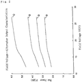
- Fig.2 is a graph representing characteristics of an output power P for a field voltage Vf applied to the field coil 3 of the 3 ⁇ phase alternator 1 used in general, and is more particularly the maximum output characteristics, wherein the output voltage is set so that a maximum output voltage is obtained for each rotating speed.
- a curve 1 ⁇ shows characteristics at the condition where the rotating speed is 4,000 rpm and the output voltage is 40V
- a curve 2 ⁇ shows characteristics at a condition where the rotating speed is 3,000 rpm and the output voltage is 30V.
- a curve 3 ⁇ and a curve 4 ⁇ respectively show characteristics at the condition of 2,500 rpm with 25V and 2,000 rpm with 20V.
- the maximum output power P of the 3 ⁇ phase alternator 1 increases as the field voltage Vf is increased if the rotating speed is assumed to be constant, and the output power is saturated when the field voltage Vf is increased to a certain value.
- the field voltage is approximately 12V of the voltage of the battery 5. But as shown in fig.2, it is more effective for the field voltage to be set higher than the voltage of the battery 5 for increasing the maximum output.
- the stepping ⁇ up DC/DC converter 6 in fig.1 is configured to step up the voltage of the battery 5 to a voltage of the battery 5 multiplied by a factor of 1.2 to 2.0 for applying to the field coil 3, but in an example hereafter explained 18V of the field voltage Vf in case the factor 1.5 is used.
- Fig.3 is a graph representing characteristics of an averaged output for the rotating speed in case the field voltage Vf of the 3 ⁇ phase alternator 1 being kept to a fixed value of 18V.
- a curve A shows characteristics of the alternator output power in KW
- a curve B shows a characteristics of the effective output power in KW in case the conversion efficiency of the DC/DC converter is 85%.
- the maximum output of the 3 ⁇ phase alternator 1 at each rotating speed is determined by the output voltage and the output voltage for obtaining the maximum output increases according to a rise of the rotating speed as is easily understood from the prior art of the Japanese laid open Patent No.6-12934 and fig.2. Therefore, the maximum output of the 3 ⁇ phase alternator 1 is always obtainable by changing the output voltage in response to the changing rotating speed.
- the output voltage differs according to a specification of the alternator, wherein the output voltage usually is higher than the voltage of the battery 5 above an idling zone of an internal combustion engine.
- the stepping ⁇ up DC/DC converter 6 applies 18 V of the stepped up voltage of the battery 5 to the field coil 3.
- the control unit 9 detects the switch 10 to became on for switching a load from the battery 5 to the high power load 7 by activating the power relay 8, and also controls the output voltage of the 3 ⁇ phase alternator 1 responding to the rotating speed, for example, from 16V to 40V for obtaining the maximum output from the 3 ⁇ phase alternator 1.
- the high power load is, for example, the load with a short time rating like the ice removing heater of the windshield, and the temperature of the field coil 3 rarely rises above a predetermined value under the maximum power operation. In this case if the temperature of the field coil 3 rises above the value due to an excessive field current, the temperature rise is suppressed by limiting the field current based on a detected temperature using the control unit 9.
- the load is switched from the high power load 7 to the battery 5 and simultaneously a set voltage value of the regulator 4 is switched to 12V for charging the battery 5 for returning to a normal operation.
- the temperature of the field coil 3 is detected indirectly by the control unit 9 as the field coil 3 is a rotor of the 3 ⁇ phase alternator 1.
- a temperature sensing element built in the regulator 4 and having a predetermined heat capacity or a heat dispersing circuit equivalent to the heat capacity is used for judging the temperature which varies subject to the field current by taking a temperature correlation.
- a reason why an output voltage range is limited to be controlled from 16V to 40V in response to the rotating speed of the 3 ⁇ phase alternator 1 is that an increase of the output is required only in a low rotating zone of the internal combustion engine.
- the output of the 3 ⁇ phase alternator1 is increased by increasing a magnetic force of the field coil 3 by stepping up the field current.
- the maximum output power of the 3 ⁇ phase alternator 1 is obtained by controlling the output voltage subject to the rotating speed. Therefore, the high power load 7 is capable of being operated only for the short time period, and no problem arises even when a power supply to the battery 5 is interrupted while the power is being supplied to the high power load 7.
- the adequate power can be supplied to each load by using a conventional alternator as the 3 ⁇ phase alternator 1 without complicating the control system.
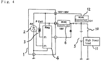
- Fig .4 is a circuit diagram of the embodiment 2 of the power supply system for the automotive vehicle according to the present invention.
- the system in the embodiment 2 is configured, wherein the adequate power with a same voltage is supplied to both a high power load 11 and a battery 5 by increasing the output power of the 3 ⁇ phase alternator 1.
- the 3 ⁇ phase alternator 1 which is vehicle ⁇ laden as in the embodiment 1 comprises the armature constructive assembly 2 including the armature winding for generating the 3 ⁇ phase AC power and the 3 ⁇ phase full wave rectifier, the field coil 3 for providing the magnetic flux to the armature winding, and the regulator 4 as the voltage control unit for controlling the field current of the field coil 3.
- the battery 5 is the vehicle ⁇ laden secondary battery.
- the stepping ⁇ up DC/DC converter 6 is for converting the voltage of the battery 5 to apply to the field coil 3
- the high power load 11 is a load such as the blower motor or the windshield heater
- the switch 10 is for supplying the power to the high power load 11
- a stepping ⁇ down DC/DC converter 12 is for stepping down the output voltage of the 3 ⁇ phase alternator 1 to apply to both the battery 5 and the high power load 11.
- the power for the high power load 11 is supplied from both the 3 ⁇ phase alternator 1 and the battery 5.
- the field voltage for example, of 18V which is stepped up by the stepping ⁇ up DC/DC converter 6 as in the embodiment 1 is applied to the field coil 3 of the 3 ⁇ phase alternator 1, whereby the output is increased and the voltage with the maximum output of the 3 ⁇ phase alternator 1 responding to the rotating speed in a predetermined rotating speed zone is obtained.
- the output voltage from 16V to 40V is obtained in response to the rotating speed.
- the stepping ⁇ down DC/DC converter 12 steps down the above voltage with the maximum output to a charging voltage of 12V for supplying the power to the high power load 11 as well as the battery 5 to be charged.
- the stepping ⁇ up DC/DC converter 6 and the stepping ⁇ down DC/DC converter 12 can be small ⁇ sized by integrating with the regulator 4. Furthermore, a temperature rise of the 3 - phase alternator 1 is suppressed by the stepping ⁇ down DC/DC converter 12 having negative gradient temperature characteristics.
Landscapes
- Engineering & Computer Science (AREA)
- Power Engineering (AREA)
- Control Of Eletrric Generators (AREA)
- Control Of Charge By Means Of Generators (AREA)
Abstract
Description
- The present invention relates to an electrical power supply system and more particularly to an electrical power supply system for an automotive vehicle for supplying power to a high power load for a short time period by increasing an alternator output.
- Recently the number of a high power load of an automotive vehicle such as a blower motor or an ice ― removing heater on a windshield is increasing. For the high power load a system is proposed, wherein a high power is extracted by using a high voltage charging alternator on the automotive vehicle.
- For example, according to a Japanese Patent No.2864887, a 3 ― phase alternator is driven by an oil pressure pump and an oil pressure motor laden in a vehicle, and an output frequency as well as a voltage of the alternator is kept constant by keeping a constant engine rotation after the engine is started. Thereby, a high voltage of the alternator with a high generating efficiency could be applied to the high power load and a battery through a stepping― down voltage converter. In this configuration a rated output of the alternator regardless of an engine rotating speed is obtained from an idling zone, and the alternator with a small size and a light weight is capable of supplying power to a high power with high voltage load. The alternator is also able to supply the required power to a low voltage load through an AC/DC voltage converter. Furthermore, a layout freedom of the alternator driven by an oil pressure is not limited but even enlarged, as the AC/DC voltage converter operating with a constant output frequency of the alternator can be small in size and light in weight.
- According to a Japanese laid open Patent No.6-12934, other effective method for supplying a power to the high power with high voltage load is disclosed. In the art a vehicle ― laden alternator output voltage with the maximum output power changes in response to a rotating speed of the alternator. To drive the high power with high voltage load which is usually existing in the idling zone, the engine rotation is being increased from an idling speed for the alternator to reach the maximum power at a second voltage set value for supplying the power, and simultaneously an attained high voltage is reduced to a voltage equal to a first voltage set value by a voltage reducing means for charging the secondary battery.
- In the former prior art although the stable alternator output is obtainable due to a constant speed driving, a rotating speed with the maximum output varies according to a load condition of the alternator. Moreover, obtaining a high voltage and a voltage for charging the secondary battery is incompatible, and an additional driving device like an oil pressure motor becomes required.
- In the latter prior art simultaneous realization of the voltages corresponding respectively to the first and the second voltage set values is intended, but due to a limitation of the alternator size sufficient power is not always supplied to the high power with high voltage load during the operation at the maximum output voltage point, and a control system becomes complicated for controlling a load distribution.
- In view of the above, it is the object of the present invention to provide an electrical power supply system for an automotive vehicle capable of supplying a required power to both a high power load and a battery.
According to this invention, an electrical power supply system for the automotive vehicle comprises: - an alternator having an armature winding and a field coil for supplying a power to both a high power load and a battery,
- a stepping―up DC/DC converter to step up a voltage of the battery for applying to the field coil,
- a voltage control means for controlling an output voltage of the alternator by controlling the current of the field coil, and
- a control means for increasing power of the alternator by changing the output voltage of the alternator in response to a rotating speed of the alternator when the alternator supplies power to the high power load, and for controlling the output voltage of the alternator to a battery charging voltage by regulating the voltage control means when the alternator supplies power to the battery.
-
- The electrical power supply system for the automotive vehicle, wherein a voltage applied to the field coil is stepped up to a voltage of the battery multiplied by a factor of 1.2 to 2.0.
- The electrical power supply system for the automotive vehicle, wherein the output voltage of the alternator changing in response to the rotating speed is set to be higher than the voltage of the battery.
- The electrical power supply system for the automotive vehicle, wherein the output voltage of the alternator changes in response to the rotating speed detected by a rotating speed detector.
- The electrical power supply system for the automotive vehicle, wherein the field current of the alternator is controlled by a detected temperature of the field coil by a temperature sensing device in the voltage control means.
- The electrical power supply system for the automotive vehicle, wherein the field current of the alternator is controlled by an inferred temperature from the field current of the alternator detected by a current detecting device in the voltage control means.
- The electrical power supply system for the automotive vehicle, wherein the stepping ― up DC/DC converter for applying the stepped up voltage of the battery to the field coil is integrated the voltage control means.
- Furthermore, according to this invention, an electrical power supply system for an automotive vehicle comprising:
- an alternator having an armature winding and a field coil for supplying a power to both a high power load and a battery,
- a stepping―up DC/DC converter to step up a voltage of the battery for applying to the field coil,
- a voltage control means for controlling an output voltage of the alternator by controlling a current of the field coil, and for increasing an output of the alternator by changing the output voltage in response to a rotating speed of the alternator in a predetermined rotating speed zone, and
- a stepping―down DC/DC converter to step down the output voltage of the alternator to a charging voltage for the battery, and to supply power with a regulated voltage to both the battery and the high power load.
-
- The electrical power supply system for the automotive vehicle, wherein the stepping ― down DC/DC converter for supplying the power to both the high power load and the battery is integrated with the voltage control means.
- The electrical power supply system for the automotive vehicle, wherein an output voltage of the stepping―down DC/DC converter has a negative gradient temperature characteristics.
- As described above in the present invention, the alternator output is increased by stepping up the field voltage. And also the maximum alternator output is obtained by controlling the output voltage to change responding to the rotating speed of the alternator. Moreover, the alternator output is controlled by detecting the temperature. Therefore, the conventional type alternator is applicable for supplying adequate power to both the high power load and the battery. In addition, the stable maximum output power of the alternator during idling up operation of the internal combustion engine is obtainable as the output voltage is subjected to the rotating speed of the alternator. Furthermore, the reliable , inexpensive and small ― sized power supply system is realized by avoiding sophistication of a control system,
- Fig. 1 is a schematic diagram of a power supply system for an automotive vehicle according to an
embodiment 1 of the present invention. - Fig. 2 is a graph representing characteristics of the power supply system for the automotive vehicle for explaining operation in the
embodiment 1 of the present invention. - Fig. 3 is a graph representing characteristics of the power supply system for the automotive vehicle for explaining operation in the
embodiment 1 of the present invention. - Fig. 4 is a schematic diagram of the power supply system for the automotive vehicle according to an
embodiment 2 of the present invention. - Fig. 1 is a circuit diagram of an electrical power supply system according to an
embodiment 1 of the present invention. Fig.2 is a graph representing output characteristics of an alternator for a field voltage of a 3― phase alternator on a vehicle according to the present invention. Fig .3 is a graph representing output characteristics of the alternator for a rotating speed according to the present invention in case a field current is set to a predetermined value. - In fig. 1 the alternator is, for example, a 3 ―
phase alternator 1 on a vehicle comprising an armatureconstructive assembly 2 including an armature winding for generating a 3 ― phase AC power and a 3―phase full wave rectifier for rectifying the 3 ― phase AC power, afield coil 3 for providing a magnetic flux to the armature winding, and aregulator 4 as a voltage control means for controlling a field current of thefield coil 3. Abattery 5 is a vehicle ― laden secondary battery. A stepping―up DC/DC converter 6 is for stepping up a voltage of abattery 5 to apply to thefield coil 3, and thebattery 5 is charged by the 3 ―phase alternator 1 for supplying a power to a load except for ahigh power load 7 for a short time period. - The
high power load 7 is a load such as a blower motor or a windshield heater driven directly by a high voltage of the 3 ―phase alternator 1. Apower relay 8 switches a power supplied from the 3―phase alternator 1 to thebattery 5 for charging or to thehigh power load 7. Acontrol unit 9 detects a on/off state of aswitch 10 for supplying power to thehigh power load 7, and switches thepower relay 8 to thebattery 5 for charging or to thehigh power load 7. Moreover, thecontrol unit 9 is configured to command theregulator 4, whereby an output voltage of the 3 ―phase alternator 1 is switched to a low charging voltage for thebattery 5 or a high voltage for thehigh power load 7. In addition, although not shown in fig.1, thecontrol unit 9 is configured such that a voltage applied to thehigh power load 7 is made to correspond to a detected rotating speed of the 3 ―phase alternator 1, and that an output of the 3 ―phase alternator 1 is suppressed by detecting a temperature of thefield coil 3. - Fig.2 is a graph representing characteristics of an output power P for a field voltage Vf applied to the
field coil 3 of the 3―phase alternator 1 used in general, and is more particularly the maximum output characteristics, wherein the output voltage is set so that a maximum output voltage is obtained for each rotating speed. In fig.2, acurve 1 ○ shows characteristics at the condition where the rotating speed is 4,000 rpm and the output voltage is 40V, acurve 2 ○ shows characteristics at a condition where the rotating speed is 3,000 rpm and the output voltage is 30V. Similarly, acurve 3 ○ and acurve 4 ○ respectively show characteristics at the condition of 2,500 rpm with 25V and 2,000 rpm with 20V. In this fig.2, the maximum output power P of the 3 ―phase alternator 1 increases as the field voltage Vf is increased if the rotating speed is assumed to be constant, and the output power is saturated when the field voltage Vf is increased to a certain value. In case of the 3―phase alternator 1 which is usually vehicle―laden , the field voltage is approximately 12V of the voltage of thebattery 5. But as shown in fig.2, it is more effective for the field voltage to be set higher than the voltage of thebattery 5 for increasing the maximum output. - On the other hand, there is a limitation in an increase of the field voltage Vf due to saturation characteristics of the output power and a temperature rise. Therefore, the field voltage is effectively obtained by stepping up the battery voltage by a factor of 1.2 to 2.0. Thus, the adequate output for driving the
high power load 7 for a short time period is obtainable, and the 3 ―phase alternator 1 can resist a short time temperature rise of thefield coil 3. Therefore, the stepping―up DC/DC converter 6 in fig.1 is configured to step up the voltage of thebattery 5 to a voltage of thebattery 5 multiplied by a factor of 1.2 to 2.0 for applying to thefield coil 3, but in an example hereafter explained 18V of the field voltage Vf in case the factor 1.5 is used. - Fig.3 is a graph representing characteristics of an averaged output for the rotating speed in case the field voltage Vf of the 3―
phase alternator 1 being kept to a fixed value of 18V. In fig.3, a curve A shows characteristics of the alternator output power in KW, and a curve B shows a characteristics of the effective output power in KW in case the conversion efficiency of the DC/DC converter is 85%. As shown in this fig.3, although the averaged output of the 3―phase alternator 1 increases responding to an increase of the rotating speed, the maximum output of the 3 ―phase alternator 1 at each rotating speed is determined by the output voltage and the output voltage for obtaining the maximum output increases according to a rise of the rotating speed as is easily understood from the prior art of the Japanese laid open Patent No.6-12934 and fig.2. Therefore, the maximum output of the 3―phase alternator 1 is always obtainable by changing the output voltage in response to the changing rotating speed. The output voltage differs according to a specification of the alternator, wherein the output voltage usually is higher than the voltage of thebattery 5 above an idling zone of an internal combustion engine. - In the
embodiment 1 according to the present invention of the power supply system for the automotive vehicle as described above, the stepping―up DC/DC converter 6 applies 18 V of the stepped up voltage of thebattery 5 to thefield coil 3. Thecontrol unit 9 detects theswitch 10 to became on for switching a load from thebattery 5 to thehigh power load 7 by activating thepower relay 8, and also controls the output voltage of the 3―phase alternator 1 responding to the rotating speed, for example, from 16V to 40V for obtaining the maximum output from the 3―phase alternator 1. The high power load is, for example, the load with a short time rating like the ice removing heater of the windshield, and the temperature of thefield coil 3 rarely rises above a predetermined value under the maximum power operation. In this case if the temperature of thefield coil 3 rises above the value due to an excessive field current, the temperature rise is suppressed by limiting the field current based on a detected temperature using thecontrol unit 9. - When an off state of the
switch 10 is detected by thecontrol unit 9, the load is switched from thehigh power load 7 to thebattery 5 and simultaneously a set voltage value of theregulator 4 is switched to 12V for charging thebattery 5 for returning to a normal operation. Moreover, the temperature of thefield coil 3 is detected indirectly by thecontrol unit 9 as thefield coil 3 is a rotor of the 3―phase alternator 1. For example a temperature sensing element built in theregulator 4 and having a predetermined heat capacity or a heat dispersing circuit equivalent to the heat capacity is used for judging the temperature which varies subject to the field current by taking a temperature correlation. Furthermore, a reason why an output voltage range is limited to be controlled from 16V to 40V in response to the rotating speed of the 3―phase alternator 1 is that an increase of the output is required only in a low rotating zone of the internal combustion engine. - As heretofore explained, in the
embodiment 1 of the power supply system for the automotive vehicle according to the present invention, the output of the 3―phase alternator1 is increased by increasing a magnetic force of thefield coil 3 by stepping up the field current. In this way the maximum output power of the 3―phase alternator 1 is obtained by controlling the output voltage subject to the rotating speed. Therefore, thehigh power load 7 is capable of being operated only for the short time period, and no problem arises even when a power supply to thebattery 5 is interrupted while the power is being supplied to thehigh power load 7. Thus, the adequate power can be supplied to each load by using a conventional alternator as the 3―phase alternator 1 without complicating the control system. - Fig .4 is a circuit diagram of the
embodiment 2 of the power supply system for the automotive vehicle according to the present invention. The system in theembodiment 2 is configured, wherein the adequate power with a same voltage is supplied to both ahigh power load 11 and abattery 5 by increasing the output power of the 3―phase alternator 1. As shown in fig.4, the 3―phase alternator 1 which is vehicle― laden as in theembodiment 1 comprises the armatureconstructive assembly 2 including the armature winding for generating the 3 ― phase AC power and the 3 ― phase full wave rectifier, thefield coil 3 for providing the magnetic flux to the armature winding, and theregulator 4 as the voltage control unit for controlling the field current of thefield coil 3. - The
battery 5 is the vehicle―laden secondary battery. The stepping―up DC/DC converter 6 is for converting the voltage of thebattery 5 to apply to thefield coil 3, thehigh power load 11 is a load such as the blower motor or the windshield heater, theswitch 10 is for supplying the power to thehigh power load 11, a stepping― down DC/DC converter 12 is for stepping down the output voltage of the 3 ―phase alternator 1 to apply to both thebattery 5 and thehigh power load 11. In theembodiment 2 the power for thehigh power load 11 is supplied from both the 3―phase alternator 1 and thebattery 5. - In the power supply system for the automotive vehicle as explained in the
embodiment 2, the field voltage, for example, of 18V which is stepped up by the stepping―up DC/DC converter 6 as in theembodiment 1 is applied to thefield coil 3 of the 3―phase alternator 1, whereby the output is increased and the voltage with the maximum output of the 3 ―phase alternator 1 responding to the rotating speed in a predetermined rotating speed zone is obtained. For example the output voltage from 16V to 40V is obtained in response to the rotating speed. - The stepping― down DC/
DC converter 12 steps down the above voltage with the maximum output to a charging voltage of 12V for supplying the power to thehigh power load 11 as well as thebattery 5 to be charged. The stepping―up DC/DC converter 6 and the stepping― down DC/DC converter 12 can be small―sized by integrating with theregulator 4. Furthermore, a temperature rise of the 3 -phase alternator 1 is suppressed by the stepping― down DC/DC converter 12 having negative gradient temperature characteristics. - In fig. 2 representing a case of the
embodiment 1, both the averaged output of the 3―phase alternator 1 and the output are shown in case a conversion efficiency of the stepping― down DC/DC converter 12 is 85%. And even taking into consideration the above conversion efficiency of 85 % of the stepping― down DC/DC converter 12, the high power of the 3―phase alternator 1 is obtainable by stepping up the field voltage Vf and by setting the output voltage in response to the rotating speed. Therefore, the adequate power is capable of being supplied to both thehigh power load 11 driven in the low rotating speed
zone and thebattery 5. In addition, a conventional operation is quite the same with an operation of the present invention in that when the idling up operation is initiated by energizing theswitch 10 to on state, the rotating speed of the internal combustion engine and the 3―phase alternator 1 is increased accordingly.
Claims (10)
- An electrical power supply system for an automotive vehicle comprising:an alternator having an armature winding and a field coil for supplying a power to both a high power load and a battery,a stepping―up DC/DC converter to step up a voltage of said battery for applying to said field coil,a voltage control means for controlling an output voltage of said alternator by controlling a current of said field coil, anda control means for increasing power of said alternator by changing said output voltage of said alternator in response to a rotating speed of said alternator when said alternator supplies power to said high power load ,and for controlling said output voltage of said alternator to a battery charging voltage by regulating said voltage control means when said alternator supplies power to said battery.
- The electrical power supply system for the automotive vehicle according to claim 1, wherein a voltage applied to said field coil is stepped up to a voltage of the battery multiplied by a factor of 1.2 to2.0.
- The electrical power supply system for the automotive vehicle according to claim 1, wherein said output voltage of said alternator changing in response to said rotating speed is set to be higher than said voltage of said battery.
- The electrical power supply system for the automotive vehicle according to claim 1, wherein said output voltage of said alternator changes in response to said rotating speed detected by a rotating speed detector.
- The electrical power supply system for the automotive vehicle according to claim 1,wherein said field current of said alternator is controlled by a detected temperature of said field coil by a temperature sensing device in said voltage control means .
- The electrical power supply system for the automotive vehicle according to claim 1,wherein said field current of said alternator is controlled by an inferred temperature from said field current of said alternator detected by a current detecting device in said voltage control means .
- The electrical power supply system for the automotive vehicle according to claim 1, wherein said stepping ― up DC/DC converter for applying said stepped up voltage of said battery to said field coil is integrated with said voltage control means.
- An electrical power supply system for an automotive vehicle comprisingan alternator having an armature winding and a field coil for supplying a power to both a high power load and a battery,an alternator having an armature winding and a field coil for supplying a power to both a high power load and a battery.a stepping―up DC/DC converter to step up a voltage of said battery for applying to said field coil,a voltage control means for controlling an output voltage of said alternator by controlling a current of said field coil, and for increasing an output of said alternator by changing said output voltage in response to a rotating speed of said alternator in a predetermined rotating speed zone, anda stepping― down DC/DC converter to step down said output voltage of said alternator to a charging voltage for said battery, and to supply power with a regulated voltage to both said battery and said high power load.
- The electrical power supply system for the automotive vehicle according to claim 8, wherein said stepping down DC/DC converter for supplying said power to both said high power load and said battery is integrated with said voltage control means.
- The electrical power supply system for the automotive vehicle according to claim 8, wherein an output voltage of said stepping― down DC/DC converter has negative gradient temperature characteristics.
Applications Claiming Priority (2)
| Application Number | Priority Date | Filing Date | Title |
|---|---|---|---|
| JP2000270398 | 2000-09-06 | ||
| JP2000270398A JP3595252B2 (en) | 2000-09-06 | 2000-09-06 | Power supply system for vehicles |
Publications (3)
| Publication Number | Publication Date |
|---|---|
| EP1186476A2 true EP1186476A2 (en) | 2002-03-13 |
| EP1186476A3 EP1186476A3 (en) | 2006-06-28 |
| EP1186476B1 EP1186476B1 (en) | 2015-04-22 |
Family
ID=18756845
Family Applications (1)
| Application Number | Title | Priority Date | Filing Date |
|---|---|---|---|
| EP20010104499 Expired - Lifetime EP1186476B1 (en) | 2000-09-06 | 2001-03-01 | Electrical power supply system for a vehicle |
Country Status (4)
| Country | Link |
|---|---|
| US (1) | US7176659B2 (en) |
| EP (1) | EP1186476B1 (en) |
| JP (1) | JP3595252B2 (en) |
| KR (1) | KR100436692B1 (en) |
Cited By (2)
| Publication number | Priority date | Publication date | Assignee | Title |
|---|---|---|---|---|
| WO2009056964A2 (en) * | 2007-11-02 | 2009-05-07 | Toyota Jidosha Kabushiki Kaisha | Power generation control device, vehicle equipped with power generation control device, and power generation control method |
| EP1622430A3 (en) * | 2004-07-28 | 2010-01-13 | Robert Bosch Gmbh | Voltage stabilizing device |
Families Citing this family (19)
| Publication number | Priority date | Publication date | Assignee | Title |
|---|---|---|---|---|
| AU2002368382B2 (en) | 2002-11-26 | 2006-10-19 | Mitsubishi Denki Kabushiki Kaisha | Controller of AC generator for vehicle |
| EP1717945B1 (en) * | 2004-02-19 | 2020-05-13 | Denso Corporation | Motor driving apparatus |
| CA2459696A1 (en) * | 2004-03-04 | 2005-09-04 | Tm4 Inc. | System and method for starting a combustion engine of a hybrid vehicle |
| DE102004041511A1 (en) * | 2004-08-27 | 2006-03-02 | Robert Bosch Gmbh | Voltage regulator with overvoltage protection |
| DE102006016138B4 (en) * | 2006-04-06 | 2014-11-20 | Robert Bosch Gmbh | Hybrid drive with emergency start option |
| JP2008167541A (en) * | 2006-12-27 | 2008-07-17 | Denso Corp | Detection method for anomaly in charging wire |
| KR101294491B1 (en) * | 2007-12-10 | 2013-08-07 | 현대자동차주식회사 | Alternator electricity generation system using a voltage conversion device |
| US8917058B2 (en) * | 2010-01-22 | 2014-12-23 | Toyota Jidosha Kabushiki Kaisha | Battery charging control system |
| JP5345172B2 (en) * | 2011-03-30 | 2013-11-20 | 三菱電機株式会社 | Power generation control device for vehicle alternator |
| US8975886B2 (en) * | 2011-11-08 | 2015-03-10 | Texas Instruments Incorporated | Charging and distribution control |
| DE102011090074A1 (en) * | 2011-12-29 | 2013-07-04 | Robert Bosch Gmbh | Line unit e.g. low impedance power cable, for electrical system voltage circuit i.e. starter circuit, of motor vehicle, has line section connected between two connection ends and comprising inductance portion |
| US9562715B2 (en) * | 2012-03-21 | 2017-02-07 | Thermo King Corporation | Power regulation system for a mobile environment-controlled unit and method of controlling the same |
| DE102013213929A1 (en) * | 2013-07-16 | 2015-01-22 | Robert Bosch Gmbh | On-board network system for a motor vehicle |
| DE102014222337B3 (en) * | 2014-10-31 | 2016-01-21 | Continental Teves Ag & Co. Ohg | Method and device for controlling a foreign-excited electric generator in a vehicle electrical system of a motor vehicle |
| ES2890834T3 (en) | 2016-06-28 | 2022-01-24 | Martin Special Technics Gmbh | Power generation system with a generator and method of operation of said power generation system |
| IT201600112547A1 (en) * | 2016-11-08 | 2018-05-08 | Magneti Marelli Spa | "Energy management apparatus supplied to a low voltage system of a motor vehicle including an energy recovery stage and related procedure" |
| IT201600112523A1 (en) * | 2016-11-08 | 2018-05-08 | Magneti Marelli Spa | "Energy management apparatus supplied to a low voltage system of a motor vehicle comprising an energy recovery stage and relative process" |
| JP6988543B2 (en) * | 2018-02-16 | 2022-01-05 | トヨタ自動車株式会社 | Power system |
| DE102020200430A1 (en) * | 2020-01-15 | 2021-07-15 | Robert Bosch Gesellschaft mit beschränkter Haftung | Electrically excited synchronous machine with one excitation circuit |
Citations (2)
| Publication number | Priority date | Publication date | Assignee | Title |
|---|---|---|---|---|
| JPH0612934A (en) | 1992-06-25 | 1994-01-21 | Ryoden Kasei Co Ltd | Manufacture of arc extinguishing material |
| JP2864887B2 (en) | 1992-08-05 | 1999-03-08 | 日産自動車株式会社 | Power supply system for vehicles |
Family Cites Families (29)
| Publication number | Priority date | Publication date | Assignee | Title |
|---|---|---|---|---|
| JPH01186200A (en) | 1988-01-20 | 1989-07-25 | Mitsubishi Electric Corp | Controller of ac generator for car |
| JPH0612934B2 (en) * | 1988-02-23 | 1994-02-16 | 日本電装株式会社 | Vehicle charge control device |
| JP2762469B2 (en) | 1988-08-04 | 1998-06-04 | 株式会社デンソー | Vehicle charging control device |
| CA2003191A1 (en) * | 1988-11-21 | 1990-05-21 | Shigeki Tezuka | Electric power supply system for automobile |
| JPH0650480B2 (en) * | 1989-05-02 | 1994-06-29 | 株式会社日立製作所 | Multiple virtual memory system and address controller |
| JP2526667B2 (en) | 1989-06-05 | 1996-08-21 | 三菱電機株式会社 | Charge generator |
| US5231344A (en) * | 1990-01-17 | 1993-07-27 | Hitachi Ltd. | Control apparatus for electric generator |
| JP2528995B2 (en) | 1990-03-19 | 1996-08-28 | 株式会社日立製作所 | In-vehicle generator control system |
| US5280231A (en) * | 1990-07-02 | 1994-01-18 | Nippondenso Co., Ltd. | Battery condition detecting apparatus and charge control apparatus for automobile |
| US5418401A (en) * | 1991-10-29 | 1995-05-23 | Mitsubishi Denki Kabushiki Kaisha | Power supply apparatus for a vehicle having batteries of different voltages which are charged according to alternator speed |
| US5499178A (en) * | 1991-12-16 | 1996-03-12 | Regents Of The University Of Minnesota | System for reducing harmonics by harmonic current injection |
| US5552681A (en) * | 1992-03-06 | 1996-09-03 | Hino Jidosha Kogyo Kabushiki Kaisha | Apparatus for storing energy generated during breaking of a vehicle and for providing energy to the internal combustion engine of the vehicle at other times |
| KR960006484B1 (en) * | 1992-09-24 | 1996-05-16 | 마쯔시다 덴기 산교 가부시끼가이샤 | Cache memory device |
| JPH06225599A (en) * | 1992-10-14 | 1994-08-12 | Ford Motor Co | Output power controller of generator for car |
| JPH06178459A (en) * | 1992-12-07 | 1994-06-24 | Nippondenso Co Ltd | Charging device for vehicle |
| US5606244A (en) * | 1993-08-05 | 1997-02-25 | Ofer Energies Ltd. | Mobile AC power source system |
| US5621896A (en) * | 1994-06-01 | 1997-04-15 | Motorola, Inc. | Data processor with unified store queue permitting hit under miss memory accesses |
| US5663631A (en) * | 1994-07-19 | 1997-09-02 | Nippondenso Co., Ltd. | Generator with circuitry for controlling power generation based on rotational speed |
| JP3375774B2 (en) * | 1995-02-28 | 2003-02-10 | 三菱電機株式会社 | Alternator-powered electric heating controller |
| JP3724026B2 (en) * | 1995-04-24 | 2005-12-07 | 株式会社デンソー | Synchronous power generator for vehicle and excitation control method thereof |
| JP3412330B2 (en) * | 1995-04-24 | 2003-06-03 | 株式会社デンソー | Power generation equipment for vehicles |
| US5731681A (en) * | 1995-06-28 | 1998-03-24 | Hitachi Koki Co., Ltd. | Motor control system for centrifugal machine |
| DE69721817D1 (en) * | 1996-12-03 | 2003-06-12 | Elliott Energy Systems Inc | ELECTRICAL ARRANGEMENT FOR TURBINE / ALTERNATOR ON COMMON AXIS |
| US6003304A (en) * | 1997-05-29 | 1999-12-21 | Stmicroelectronics, Inc. | Generator power electrically heated catalyst system |
| US5930134A (en) * | 1997-06-30 | 1999-07-27 | Sundstrand Corporation | Starting system for a prime mover |
| DE19733221A1 (en) * | 1997-08-01 | 1999-02-04 | Bosch Gmbh Robert | Process for regulating a generator |
| US6487639B1 (en) * | 1999-01-19 | 2002-11-26 | International Business Machines Corporation | Data cache miss lookaside buffer and method thereof |
| US6473832B1 (en) * | 1999-05-18 | 2002-10-29 | Advanced Micro Devices, Inc. | Load/store unit having pre-cache and post-cache queues for low latency load memory operations |
| US6184661B1 (en) * | 1999-06-22 | 2001-02-06 | C. E. Niehoff & Co. | Regulator with alternator output current and input drive power control |
-
2000
- 2000-09-06 JP JP2000270398A patent/JP3595252B2/en not_active Expired - Fee Related
-
2001
- 2001-03-01 EP EP20010104499 patent/EP1186476B1/en not_active Expired - Lifetime
- 2001-03-21 US US09/813,348 patent/US7176659B2/en not_active Expired - Lifetime
- 2001-05-18 KR KR10-2001-0027188A patent/KR100436692B1/en active IP Right Grant
Patent Citations (2)
| Publication number | Priority date | Publication date | Assignee | Title |
|---|---|---|---|---|
| JPH0612934A (en) | 1992-06-25 | 1994-01-21 | Ryoden Kasei Co Ltd | Manufacture of arc extinguishing material |
| JP2864887B2 (en) | 1992-08-05 | 1999-03-08 | 日産自動車株式会社 | Power supply system for vehicles |
Cited By (3)
| Publication number | Priority date | Publication date | Assignee | Title |
|---|---|---|---|---|
| EP1622430A3 (en) * | 2004-07-28 | 2010-01-13 | Robert Bosch Gmbh | Voltage stabilizing device |
| WO2009056964A2 (en) * | 2007-11-02 | 2009-05-07 | Toyota Jidosha Kabushiki Kaisha | Power generation control device, vehicle equipped with power generation control device, and power generation control method |
| WO2009056964A3 (en) * | 2007-11-02 | 2009-08-20 | Toyota Motor Co Ltd | Power generation control device, vehicle equipped with power generation control device, and power generation control method |
Also Published As
| Publication number | Publication date |
|---|---|
| KR20020020174A (en) | 2002-03-14 |
| KR100436692B1 (en) | 2004-06-22 |
| EP1186476A3 (en) | 2006-06-28 |
| US7176659B2 (en) | 2007-02-13 |
| US20020027425A1 (en) | 2002-03-07 |
| JP2002084672A (en) | 2002-03-22 |
| JP3595252B2 (en) | 2004-12-02 |
| EP1186476B1 (en) | 2015-04-22 |
Similar Documents
| Publication | Publication Date | Title |
|---|---|---|
| US7176659B2 (en) | Vehicle electrical power supply system for supplying power to a high power load | |
| KR100498733B1 (en) | Hybrid vehicle and control method therefor | |
| EP0539982B1 (en) | Power supply apparatus for a vehicle | |
| US6051951A (en) | Generator motor for internal combustion engine | |
| US6153942A (en) | Starter/generator speed sensing using field weakening | |
| US5581168A (en) | Starter/generator system with DC link current control | |
| JP2002524686A (en) | Starter system for internal combustion engine and method for starting internal combustion engine | |
| US7135784B2 (en) | Fast torque control of a belted alternator starter | |
| JP4119492B2 (en) | Generator control method | |
| WO2006137200A1 (en) | Apparatus for controlling electric power generation of rotation electric machine used for vehicle | |
| US8710808B2 (en) | Power supply system for motor vehicle | |
| JP2003102200A (en) | Inverter system generator | |
| US8339074B2 (en) | Power converter control apparatus | |
| US7157885B2 (en) | Inverter controlled generator set and method for controlling the same | |
| US5642021A (en) | Method and system for controlling an alternator to optimize direct current output | |
| JPH0937597A (en) | Generator for vehicle | |
| JPH07115704A (en) | Retarder | |
| US6703808B1 (en) | Active power limiting for starter/alternator in the generation mode | |
| JP2570745B2 (en) | Vehicle charging control device | |
| CN103975520A (en) | Method for operating a separately excited electric machine in a motor vehicle | |
| JP3506169B2 (en) | Power supply for internal combustion engine | |
| JPH10225171A (en) | Starter system of brushless dc motor | |
| JP2866523B2 (en) | Vehicle power supply | |
| JPH09233831A (en) | Inverter charging controller | |
| JP3064787B2 (en) | Retarder device |
Legal Events
| Date | Code | Title | Description |
|---|---|---|---|
| PUAI | Public reference made under article 153(3) epc to a published international application that has entered the european phase |
Free format text: ORIGINAL CODE: 0009012 |
|
| AK | Designated contracting states |
Kind code of ref document: A2 Designated state(s): AT BE CH CY DE DK ES FI FR GB GR IE IT LI LU MC NL PT SE TR |
|
| AX | Request for extension of the european patent |
Free format text: AL;LT;LV;MK;RO;SI |
|
| RAP1 | Party data changed (applicant data changed or rights of an application transferred) |
Owner name: MITSUBISHI DENKI KABUSHIKI KAISHA |
|
| PUAL | Search report despatched |
Free format text: ORIGINAL CODE: 0009013 |
|
| AK | Designated contracting states |
Kind code of ref document: A3 Designated state(s): AT BE CH CY DE DK ES FI FR GB GR IE IT LI LU MC NL PT SE TR |
|
| AX | Request for extension of the european patent |
Extension state: AL LT LV MK RO SI |
|
| RIC1 | Information provided on ipc code assigned before grant |
Ipc: H02J 7/14 20060101ALI20060519BHEP Ipc: B60R 16/02 20060101AFI20011126BHEP |
|
| 17P | Request for examination filed |
Effective date: 20060823 |
|
| AKX | Designation fees paid |
Designated state(s): DE FR GB |
|
| 17Q | First examination report despatched |
Effective date: 20081114 |
|
| GRAP | Despatch of communication of intention to grant a patent |
Free format text: ORIGINAL CODE: EPIDOSNIGR1 |
|
| INTG | Intention to grant announced |
Effective date: 20141020 |
|
| RIN1 | Information on inventor provided before grant (corrected) |
Inventor name: GODA, TUNEJI Inventor name: IWATANI, SHIROU Inventor name: MATSUMURA, KYOJI Inventor name: WATANABE, HIROHUMI Inventor name: ASAO, YOSHIHITO Inventor name: ADACHI, KATSUMI |
|
| GRAS | Grant fee paid |
Free format text: ORIGINAL CODE: EPIDOSNIGR3 |
|
| GRAA | (expected) grant |
Free format text: ORIGINAL CODE: 0009210 |
|
| AK | Designated contracting states |
Kind code of ref document: B1 Designated state(s): DE FR GB |
|
| REG | Reference to a national code |
Ref country code: GB Ref legal event code: FG4D |
|
| REG | Reference to a national code |
Ref country code: DE Ref legal event code: R096 Ref document number: 60149326 Country of ref document: DE Effective date: 20150528 |
|
| REG | Reference to a national code |
Ref country code: DE Ref legal event code: R097 Ref document number: 60149326 Country of ref document: DE |
|
| REG | Reference to a national code |
Ref country code: FR Ref legal event code: PLFP Year of fee payment: 16 |
|
| PLBE | No opposition filed within time limit |
Free format text: ORIGINAL CODE: 0009261 |
|
| STAA | Information on the status of an ep patent application or granted ep patent |
Free format text: STATUS: NO OPPOSITION FILED WITHIN TIME LIMIT |
|
| 26N | No opposition filed |
Effective date: 20160125 |
|
| REG | Reference to a national code |
Ref country code: FR Ref legal event code: PLFP Year of fee payment: 17 |
|
| REG | Reference to a national code |
Ref country code: DE Ref legal event code: R084 Ref document number: 60149326 Country of ref document: DE |
|
| REG | Reference to a national code |
Ref country code: GB Ref legal event code: 746 Effective date: 20170424 |
|
| REG | Reference to a national code |
Ref country code: FR Ref legal event code: PLFP Year of fee payment: 18 |
|
| PGFP | Annual fee paid to national office [announced via postgrant information from national office to epo] |
Ref country code: GB Payment date: 20180228 Year of fee payment: 18 Ref country code: DE Payment date: 20180214 Year of fee payment: 18 |
|
| PGFP | Annual fee paid to national office [announced via postgrant information from national office to epo] |
Ref country code: FR Payment date: 20180223 Year of fee payment: 18 |
|
| REG | Reference to a national code |
Ref country code: DE Ref legal event code: R119 Ref document number: 60149326 Country of ref document: DE |
|
| GBPC | Gb: european patent ceased through non-payment of renewal fee |
Effective date: 20190301 |
|
| PG25 | Lapsed in a contracting state [announced via postgrant information from national office to epo] |
Ref country code: GB Free format text: LAPSE BECAUSE OF NON-PAYMENT OF DUE FEES Effective date: 20190301 Ref country code: DE Free format text: LAPSE BECAUSE OF NON-PAYMENT OF DUE FEES Effective date: 20191001 |
|
| PG25 | Lapsed in a contracting state [announced via postgrant information from national office to epo] |
Ref country code: FR Free format text: LAPSE BECAUSE OF NON-PAYMENT OF DUE FEES Effective date: 20190331 |