EP1186447A2 - Method of making finite element tire model - Google Patents
Method of making finite element tire model Download PDFInfo
- Publication number
- EP1186447A2 EP1186447A2 EP01121298A EP01121298A EP1186447A2 EP 1186447 A2 EP1186447 A2 EP 1186447A2 EP 01121298 A EP01121298 A EP 01121298A EP 01121298 A EP01121298 A EP 01121298A EP 1186447 A2 EP1186447 A2 EP 1186447A2
- Authority
- EP
- European Patent Office
- Prior art keywords
- tire
- rubber
- cord
- stiffness
- tread
- Prior art date
- Legal status (The legal status is an assumption and is not a legal conclusion. Google has not performed a legal analysis and makes no representation as to the accuracy of the status listed.)
- Granted
Links
Images





Classifications
-
- B—PERFORMING OPERATIONS; TRANSPORTING
- B60—VEHICLES IN GENERAL
- B60C—VEHICLE TYRES; TYRE INFLATION; TYRE CHANGING; CONNECTING VALVES TO INFLATABLE ELASTIC BODIES IN GENERAL; DEVICES OR ARRANGEMENTS RELATED TO TYRES
- B60C3/00—Tyres characterised by the transverse section
-
- B—PERFORMING OPERATIONS; TRANSPORTING
- B60—VEHICLES IN GENERAL
- B60C—VEHICLE TYRES; TYRE INFLATION; TYRE CHANGING; CONNECTING VALVES TO INFLATABLE ELASTIC BODIES IN GENERAL; DEVICES OR ARRANGEMENTS RELATED TO TYRES
- B60C19/00—Tyre parts or constructions not otherwise provided for
-
- B—PERFORMING OPERATIONS; TRANSPORTING
- B60—VEHICLES IN GENERAL
- B60C—VEHICLE TYRES; TYRE INFLATION; TYRE CHANGING; CONNECTING VALVES TO INFLATABLE ELASTIC BODIES IN GENERAL; DEVICES OR ARRANGEMENTS RELATED TO TYRES
- B60C99/00—Subject matter not provided for in other groups of this subclass
- B60C99/006—Computer aided tyre design or simulation
-
- G—PHYSICS
- G06—COMPUTING OR CALCULATING; COUNTING
- G06F—ELECTRIC DIGITAL DATA PROCESSING
- G06F30/00—Computer-aided design [CAD]
- G06F30/10—Geometric CAD
- G06F30/15—Vehicle, aircraft or watercraft design
-
- G—PHYSICS
- G06—COMPUTING OR CALCULATING; COUNTING
- G06F—ELECTRIC DIGITAL DATA PROCESSING
- G06F30/00—Computer-aided design [CAD]
- G06F30/20—Design optimisation, verification or simulation
- G06F30/23—Design optimisation, verification or simulation using finite element methods [FEM] or finite difference methods [FDM]
Definitions
- the present invention relates to a method of making a finite element model of a pneumatic tire used in a finite element method to analyze tire performance, tire behavior and the like and suitably used to simulate a system including pneumatic tires.
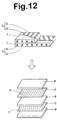
- a finite element tire mode is disclosed, wherein, as shown in Fig.12, a cord layer (b) is modeled by a quadrangular membrane element (d) and a rubber layer (c) is modeled by a hexahedral solid element (e).
- a cord layer (b) is modeled by a quadrangular membrane element (d)
- a rubber layer (c) is modeled by a hexahedral solid element (e).
- the number of the elements is five and the number of nodes of the superposed elements is twenty four.
- the computation load is not so light.
- an object of the present invention to provide a method of making a finite element model of a pneumatic tire, in which the number of finite elements can be decreased and speedup of computation time is possible without sacrificing accuracy of analyses and simulation.
- a method of making a finite element model of a pneumatic tire comprises
- a shell element itself has no thickness when viewed from the coordinates of its nodes, but it may have data relating to the thickness of the objective layer(s) in addition to other data relating to the physical properties, e.g. Young's modulus, Poisson's ratio, specific gravity and the like.
- a membrane element is an element such that forces to be considered are only those in its plane, namely, it delivers only tension, compression and shearing force along the plane. Thus, it has no data relating to forces outside its plane and accordingly bending stress, bending stiffness and the like can not be handled. Therefore, it may be said that a major difference between a shell element and a membrane element is that the shell element has a bending stiffness but the membrane element dose not have its bending stiffness.
- a typical structure of a pneumatic tire T is illustrated according to Fig.1.
- the tire T is composed of a tread portion 2, a pair of axially spaced bead portions 3 and a pair of sidewall portions 3, and it has a toroidal shape.
- each "portion” means neither a surface of the tire nor a rubber component. It means a tire part between the outer surface and inner surface of the tire.
- it includes one or more rubber components 11 and one or more reinforcing cord layers 10.
- a carcass 6 and a belt (7, 9) are such reinforcing cord layers 10.
- a pull-resistant bead core 5 is disposed in each bead portion 3.
- the carcass 6 comprises at le ast one ply 6A of cords extending between the bead portions 3 through the tread portion 2 and sidewall portions 3 and turned up around the bead cores 5 to be secured thereto.
- the belt is disposed radially outside the carcass 6 in the tread portion 2, and it comprises a breaker 7 and an optional band 9 disposed on the radially outside of the breaker 7.
- the breaker 7 usually comprises two cross plies 7A and 7B each made of parallel cords inclined in one direction.
- the band 9 usually comprises a ply 9A of cords oriented in the circumferential direction of the tire.
- a tread rubber 2G is disposed in the tread portion 2 as a relatively thick rubber component on the radially outside of the belt.
- the radially outer surface of the tread rubber 2G is usually provided with tread grooves G defining a tread pattern.
- a sidewall rubber 3G is disposed axially outside the carcass 6.
- a bead rub ber 4G is disposed on the axially outside of the carcass 6. Further, a bead apex 8 made of radially outwardly tapering hard rubber is provided between a carcass ply turnup portion and carcass ply main portion, so as to extend from the radially outside of the bead core 5 in the bead portion 4 into a lower sidewall portion.
- an inner liner, a gas-impermeable rubber layer is disposed along the inner surface of the tire.
- tread portion 2 and sidewall portion 3 can be regarded as a layered complex F of alternate one or more cord layers 10 and adjacent rubber layers 11.
- the cord layers 10 include the band cord ply 9A, the breaker cord plies 7A, 7B, and the carcass cord ply 6A.
- the rubber layers 11 include the tread rubber 2G, the inner liner rubber and layers between the reinforcing cord layers 10 including topping rubber ( tg) and the like.
- the cord layers 10 include the carcass cord ply 6A which forms two layers of the turnup portion and main portion in the lower sidewall portion, but one layer of the main portion in the upper sidewall portion.
- the rubber layers 11 include the sidewall rubber 3G, the inner liner rubber and layers between the reinforcing cord layers 10 including topping rubber (tg) and the like, and the bead apex rubber 8 in the lower sidewall portion.
- the bead portions 4 are fixed between rigid rim flanges of a wheel rim on which the tire to be simulated is mounted. Therefore, usually it is not necessary to consider the bead portions 4 in simulating their elastic deformation.
- the carcass 6 is composed of a ply of organic fiber cords such as polyester arranged at substantially 90 degrees with respect the tire equator
- the breaker 7 is composed of two cross plies 7A and 7B of steel cords laid at +20 and -20 degrees with respect the tire equator (plus/minus sign means clockwise/counterclockwise)
- the band 9 is made of spirally wound organic fiber cords double in the edge portions and single in the central portion.
- Fig.2A shows a small part of the tire corresponding to a region (A) of Fig.1.
- four cord layers 10 exist - one carcass ply 6A, two breaker plies 7A and 7B, and one band ply 9A.
- the outmost rubber layer a combination of the thick tread rubber 2G and the thin topping rubber of the outmost cord layer exists.
- the radially inner most cord layer a combination of the inner liner rubber and the topping rubber for the innermost cord layer exists.
- three layers of topping rubber exist between the four cord layers 10.
- such part is preferably modeled as shown in Fig.2C, wherein the cord layers 10 are each modeled by a membrane element Ek1-Ek4 such as quadrangular membrane element, and the outermost rubber layer is modeled by solid elements Ed1 and Ed2 such as hexahedral solid element, and the rubber layers between the cord layers and the innermost rubber layer are each modeled by a hexahedral solid element Ed3-Ed6.
- the hexahedral solid elements Ed3-Ed6 for the rubber layers 11 and the membrane elements Ek1-Ek4 for the cord layers 10 are each provided with a single integral point i1-i8.
- stiffness matrixes are defined on all the integral points i1-i8 and the nodes of all the elements.
- Such a single integral point ( i) is placed on or near the center of mass of the object.
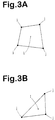
- the integral point is placed on or near the center of area of the membrane element.
- the integral point is placed on or near the center of volume of the solid element.
- An integral point is not bound to the adjacent elements unlike nodes and it is utilized together with an integral point of an adjacent element to determine a stress therebetween.
- the stress can be obtained by multiplying a strain therebetween by the Young's modulus.
- rubber layers 11 and cords layers 10 in a small part of the tire are modeled by a special single shell element Es such as trigonal shell element, quadrangular shell element and the like which is accompanied by a plurality of integral points (I) representing the rubber layers and cord layers so as to be able to simulate the bending stiffness and elongation and contraction of the complex F.
- Es such as trigonal shell element, quadrangular shell element and the like which is accompanied by a plurality of integral points (I) representing the rubber layers and cord layers so as to be able to simulate the bending stiffness and elongation and contraction of the complex F.
- Fig.2B shows a finite element model of the above-mentioned small part shown in Fig2A.
- the outermost rubber layer (tread rubber) is modeled by two solid elements Ed1 and Ed2 such as hexahedral solid elements of which boundary is set at the bottom of the deepest tread groove G.
- the remaining rubber layers and all the cords layers are modeled by a single shell element Es with eight integral points I1-I8.
- the shell element Es is positioned at the inner end of the inner solid element Ed2 and connected thereto. In other words, the coordinates of the nodes are so defined. In Fig.2B, the shell element Es is shown as having a small thickness but this is for convenience sake only.
- the integral points (I, I1-I8) correspond to the cord layers and rubber layers.
- the integral points I1, I3, I5 and I7 represent the positions and properties of the band ply 9A, the belt plies 7B and 7A, and the carcass ply 6A, respectively.
- the integral points I2, I4, I6 and I8 represent the positions and properties of three topping layers between the cord layers and one layer inside the carcass ply 6A, respectively.
- the layers are each represented by a single integral point (I), and the integral point (I) is placed on or near the center of mass of the objective layer.
- the integral point is placed on or near the center of area of a plane extending in the thickness center of the cord layer.
- the integral point is placed on or near the center of volume thereof.
- the relative positions of the above-mentioned eight integral points (i1-i8) in the Fig.2C example, namely, the spaces between them can be used for the integral points (I1-I8).
- the coordinates of the above-mentioned eight integral points (i1-i8) or the absolute positions can not be used because of the position of the shell element Es which is shifted to the inner end of the solid element Ed2.
- the stiffness matrixes of the cord layers and rubber layers are accordingly defined on the integral points I1-I8.
- the shell element Em is formed in the thickness center of the layered complex F of the cord layers 10 and rubber layers 11.
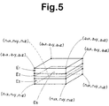
- XYZ coordinates of each of the four nodes of the shell element Es can be expressed as follows, using XYZ coordinates of the extreme nodes of the extreme elements E1 and E3:
- the tread rubber 2G is provided with tread grooves G as mentioned-above. Accordingly, properties of the tread rubber vary along the circumferential direction. However, the properties of other rubber components such as the sidewall rubber 3G, bead rubber 4G, inner liner rubber and the like are substantially constant in the circumferential direction and their variations are negligible.
- the tread rubber 2G is modeled separately from the shell element Es as explained above by the solid elements Ed, e.g. hexahedral solid element, pentahedral solid element, tetrahedral solid element and the like.
- the entire thickness including the sidewall rubber 3G, bead rubber 4G and the like may be modeled by a single shell element Es with a plurality of integral points (I).
- Such finite element dividing also h as an advantage such that when (a) the tread groove arrangement or tread pattern is changed (simulation of combination with another tread pattern), (b) the tread pattern is not changed but the tread rubber thickness is decreased (simulation of tread wear), a finite element tire model can be easily made by modeling the tread rubber only without remaking the shell elements.
- a finite element tire model can be made by
- the number of finite elements and the number of the nodes are greatly decreased. This is apparent when Fig.2B and Fig.2C are compared with each other.
- the number of the nodes of the quadrangular shell element Es is only four.
- the number of nodes of the four quadrangular membrane elements Ek1-Ek4 and the four hexahedral solid elements Ed3-Ed6 reaches twenty. Accordingly, the computation time for the determination of the nodes' positions, contingence decision between the elements and the like can be greatly decreased. Therefore, the finite element tire model can be suitably utilized to simulate a rolling tire to evaluate various dynamic tire performances by applying equations of motion, boundary conditions, load vectors and the like.
- the inventors were studied how the number of the integral points (I) can be decreased, and discovered a method to decrease the integral points (I) for example eight points (I1-I8) to two integral points IF1 and IF2.
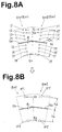
- Fig.8A shows the above-mentioned example shell element Es with eight integral points I1-I8.
- Fig.8B shows a shell element with two representative integral points IF1 and IF2.
- the stiffness matrixes are defined on the integral points I1-I8 as explained above.
- the position of the shell element Es may be the same as that in Fig.8A, and a stiffness matrix is defined on the integral point IF1 on the upper side of the shell element Es, which matrix is obtained by adding or superposing the stiffness matrixes defined on the original integral points I1, I2, I3 and I4 on the upper side of the shell element Es.
- a stiffness matrix is defined on the integral point IF2 on the lower side of the shell element Es, which is obtained by adding or superposing the original stiffness matrixes defined on the integral points 15, 16, 17 and 18 on the lower side of the shell element Es.
- the stiffness matrixes to be added should be linear matrixes so that they can be added into one. It is preferable that when adding the stiffness matrixes of the cord and rubber layers, the stiffness matrixes of the cord layers are weighted according to the thicknesses of the cord layers.
- the positions h3 and h4 of the integral points IF1 and IF2 are determined so that the total stress ⁇ B on the integral points IF1 and IF2 becomes the same as the total stress ⁇ A on the integral points (I1-I8).
- the above-mentioned method of making a finite element tire model may include a process of decreasing the integral points (I) in number to two integral points IF1 and IF2 per one shell element Es.
- the cord angle of the cord layer 10 must be taken into consideration.
- a complex F there are a plurality of cord layers each having a stiffness anisotropy such that the tensile elastic modulus is high in the cord oriented direction but low in the orthogonal direction, then it is preferable that the stiffness anisotropys are converted into one and given to the shell element Es in view of speedup of computation time.
- a stress-strain matrix (hereinafter the "D matrix”) of each cord layer is defined according to the stiffness anisotropy thereof, supposing the objective cord layer to be a shell element (hereinafter the “intermediate shell element”). Then, the D matrixes are superposed into one.
- D 1 , D 2 and D 3 are D matrixes which are obtained by rotating the intermediate shell elements 1, 2, 3 such that the cord angle becomes zero, and
- t 1 , t 2 and t 3 are the thicknesses of the shell elements 1, 2 and 3 or the objective cord layers.
- the rotated D matrix D 1 , D 2 or D 3 can be obtained by using a rotation matrix T ⁇ ( ⁇ is rotation angle) and a transposed matrix T T ⁇ of the rotation matrix T ⁇ as follows:
- the Young's modulus E and transverse elastic modulus G of the equivalent superposed shell element can be obtained as follows:
- the shell element Es in each modeling unit Em such as the above-mentioned small part in the region (A) may be said as being already provided with an average stiffness in a sense, namely, an average in the thickness direction.
- a succession of shell elements Es along a direction orthogonal to the tire circumferential direction may be given matrixes of a property, e.g. stiffness and the like which is averaged in the orthogonal direction.
- FIG.7 An example of area dividing for averaging the stiffness is shown in Fig.7.
- the area dividing and the finite element dividing (meshes) are of course closely related with each other, but they are different from each other as explained below.
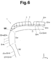
- the finite element meshes shown in Fig.6 is for the tire T shown in Fig.1.
- the tire T is roughly divided into a tread area Tr between the belt edges BE, an upper sidewall area Sw extending from the belt edge BE to the radially outer end of the bead apex rubber 8, and a lower sidewall area Bp extending radially inwardly from the radially outer end of the bead apex rubber 8.
- the bead apex rubber 8 in this example is extended to a relatively higher position above the rim flange, the radially outer end of the bead apex rubber 8 is utilized as the dividing point between the two areas Sw and Bp.
- a point at which a rubber thickness greatly changes a point at which the number of cord layers changes, a mid point of property's transition and the like are utilized as a dividing point, and a sidewall between the belt edge and a position corresponding to the rim flange's upper end is divided into two or three areas.
- the stiffness of the belt inclusive of the breaker and band is averaged in the orthogonal direction or the axial direction, and the obtained average stiffness and a stiffness matrix therefor are used for the shell element Es in every modeling unit Emt in the tread area Tr.
- the radially outer most rubber layer (tread rubber 2G) in the modeling unit Emt is separately modeled by the solid elements Ed1 and Ed2.
- each modeling unit Ems including the axially outer most rubber layer (mainly sidewall rubber 3G) is modeled by a shell element Es.
- the stiffness of the carcass is averaged in the orthogonal direction or the radial direction, and the obtained average stiffness and a stiffness matrix therefor are used for the shell element Es in every modeling unit Ems in the upper sidewall area Sw.
- the finite element tire model is made up of a chain of the shell elements Es which continues from bead to bead, and the solid elements Ed1 and Ed2 thereon for the tread rubber (incl. topping rubber).
- the above-mentioned method of making a finite element tire model may include the following processes: in a certain area along a normal direction to the tire circumferential direction,
- such a simplified tire model has merit such that, even if the cord and rubber layers 10 and 11 are changed in number, thickness, material and the like, the tire model needs to be altered a little.
- D matrix (D eq ') min can be obtained by rotating the D matrix D eq ' by a small angle "min" such that the null components become minimized.
- the angle "min" is about ten degrees at most. This was discovered as a result of examination under various conditions.
- This angle “min” may be also used as a re presentative cord angle of the shell element Es.
- the shell element Es may be provided with zero degrees as its representative cord angle, irrespective of the existence of the carcass, and that when a modeling unit Em includes the carcass but the belt (the unit Em may be in the above-mentioned sidewall area Sw ot Bd) the shell element Es may be provided with 90 degrees as its representative cord angle. Even if the representative cord angle is so defined, because of the nature of a cord reinforced pneumatic tire, the accuracy is not decreased and the computation time can be remarkably shortened.
- the above-mentioned method of making a finite element tire model may include the following processes:
- the following table 1 shows vertical spring constant of a radial tire of size 205/50R16 for passenger cars obtained by a finite element method using tire models Ex.1-Ex.4 and Ref.1.
- the results shown in table 1 are indicated as a difference in percent from the measurements on an actual tire.
- the computation time is shown as a percentage with respect to that of Ref.1 model.
- Model Ref.1 Ex.1 Ex.2 Ex.3 Ex.4 Number of elements 35000 10800 10800 10800 10800 Computing time(%) 100 55 37 30 18 Vertical spring constant Simulation error (%) @ 3.5 ⁇ 0.5 kN 3.8 0.95 4.3 0.95 -0.47 @ 8.0 ⁇ 0.5 kN 4.5 5.3 2.2 1.3 3.1
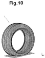
- the global image of the finite element tire model during the simulation test is printed out and shown in Fig.10.
- An enlarged image of the model cut in the middle of the ground contacting patch along a plane including the tire axis is shown in Fig.11.
Landscapes
- Engineering & Computer Science (AREA)
- Physics & Mathematics (AREA)
- Geometry (AREA)
- Theoretical Computer Science (AREA)
- General Engineering & Computer Science (AREA)
- General Physics & Mathematics (AREA)
- Computer Hardware Design (AREA)
- Mechanical Engineering (AREA)
- Evolutionary Computation (AREA)
- Computational Mathematics (AREA)
- Mathematical Analysis (AREA)
- Mathematical Optimization (AREA)
- Pure & Applied Mathematics (AREA)
- Aviation & Aerospace Engineering (AREA)
- Automation & Control Theory (AREA)
- Tires In General (AREA)
Abstract
Description
Contrary, a membrane element is an element such that forces to be considered are only those in its plane, namely, it delivers only tension, compression and shearing force along the plane. Thus, it has no data relating to forces outside its plane and accordingly bending stress, bending stiffness and the like can not be handled. Therefore, it may be said that a major difference between a shell element and a membrane element is that the shell element has a bending stiffness but the membrane element dose not have its bending stiffness.
wherein the cord layers 10 are each modeled by a membrane element Ek1-Ek4 such as quadrangular membrane element, and the outermost rubber layer is modeled by solid elements Ed1 and Ed2 such as hexahedral solid element, and the rubber layers between the cord layers and the innermost rubber layer are each modeled by a hexahedral solid element Ed3-Ed6. The hexahedral solid elements Ed3-Ed6 for the rubber layers 11 and the membrane elements Ek1-Ek4 for the cord layers 10 are each provided with a single integral point i1-i8. Further, stiffness matrixes are defined on all the integral points i1-i8 and the nodes of all the elements.
Such a single integral point ( i) is placed on or near the center of mass of the object. Thus, in case of a membrane element, as shown in Figs.3A and 3B, the integral point is placed on or near the center of area of the membrane element. In case of a solid element, as shown in Figs.4A, 4B and 4C, the integral point is placed on or near the center of volume of the solid element.
In Fig.2B, the shell element Es is shown as having a small thickness but this is for convenience sake only.
It is of course possible to determine the relative position of the shell element Es to the complex F directly without converting to solid elements and membrane elements.
As explained above, the design (a) may be applied to a part that is cut out from the tread portion 2 including the entire thickness. The design (b) may be applied to such a part that is cut out from the sidewall portion 3 including the entire thickness. However, the designs (a) and (b) are not always limited to these two applications.
In case of Fig.8B, the position of the shell element Es may be the same as that in Fig.8A, and a stiffness matrix is defined on the integral point IF1 on the upper side of the shell element Es, which matrix is obtained by adding or superposing the stiffness matrixes defined on the original integral points I1, I2, I3 and I4 on the upper side of the shell element Es. Likewise, a stiffness matrix is defined on the integral point IF2 on the lower side of the shell element Es, which is obtained by adding or superposing the original stiffness matrixes defined on the integral points 15, 16, 17 and 18 on the lower side of the shell element Es. Incidentally, the stiffness matrixes to be added should be linear matrixes so that they can be added into one.
It is preferable that when adding the stiffness matrixes of the cord and rubber layers, the stiffness matrixes of the cord layers are weighted according to the thicknesses of the cord layers.

Therefore, h3 and h4 are set to satisfy the condition σA = σB.
Giving that D matrixes D 1', D2' and D3' are of intermediate shell elements 1, 2 and 3 whose cord angles 1, 2 and 3 with respect the circumferential direction of the tire are for example +20, -20 and +20 degrees, respectively (plus/minus sign means clockwise and counterclockwise or the reverse), an equivalent D matrix D eq' which is given to the shell element Es is

in a certain area along a normal direction to the tire circumferential direction,
This was discovered as a result of examination under various conditions.
| Model | Ref.1 | Ex.1 | Ex.2 | Ex.3 | Ex.4 |
| Number of elements | 35000 | 10800 | 10800 | 10800 | 10800 |
| Computing time(%) | 100 | 55 | 37 | 30 | 18 |
| Vertical spring constant Simulation error (%) | |||||
| @ 3.5±0.5 kN | 3.8 | 0.95 | 4.3 | 0.95 | -0.47 |
| @ 8.0±0.5 kN | 4.5 | 5.3 | 2.2 | 1.3 | 3.1 |
- Ex.1:
- Each shell element was provided with integral points (I) whose number was equal to the number of cord and rubber layers as shown in Fig.2B. The finite element dividing was made as shown in Fig.6.
- Ex.2:
- Each shell element was provided with integral points (IF)
whose number was decreased to two as shown in Fig.8B.
Otherwise the model was the same as Ex.1. - Ex.3:
- Average stiffness was used in each of the tread area Tr,
upper sidewall area Sw and lower sidewall area Bd.
Otherwise the model was the same as Ex.2. - Ex.4:
- The coordinate conversion was omitted using the belt cord angle of 0 degrees, and the carcass cord angle of 90 degrees. Otherwise the model was the same as Ex.3.
- Ref.:
- Each rubber layers was modeled by a solid element and each cord layer was modeled by a membrane element as shown in Fig.2C. The finite element dividing was made as shown in Fig.9.
- Actual tire:
- The tire was mounted on a wheel rim of size 16X6.5JJ and inflated to 200 kPa, and the deflection was measured changing the vertical load from 0 to 9 kN. From the load-deflection curve, the actual measurement value was obtained as of the inclination of a segment between 3.0 and 4.0 kN load and a segment between 7.5 and 8.5 kN load.
Claims (8)
- A method of making a finite element model of a pneumatic tire comprisingdividing a pneumatic tire into a plurality of modeling units each of which is to be modeled by one or more finite elements so that said modeling units include modeling units each of which is a layered complex of at least one cord layer and at least one rubber layer, andmodeling each said modeling unit which is a layered complex by a single shell element provided with a plurality of integral points corresponding to said at least one cord layer and said at least one rubber layer.
- The method according to claim 1, which further comprisesincluding at least one integral point per one rubber layer in said a plurality of integral points, andincluding at least one integral point per one cord layer in said a plurality of integral points.
- The method according to claim 2, which further comprisesexamining whether the total number of said at least one cord layer and said at least one rubber layer in said layered complex is more than two, andif more than two, decreasing the number of said a plurality of integral points to two per one shell element, providing one on each side of the shell element.
- The method according to claim 1, which further comprisesproviding a succession of shell elements in a certain range along a orthogonal direction to the tire circumferential direction,obtaining an average of a property such as stiffness in said certain range, andgiving the average property to each of said successional shell elements.
- The method according to claim 4, whereinsaid pneumatic tire comprise a tread reinforcing belt disposed in a tire tread portion and a tread rubber on the radially outside thereof,said certain range is a tire part between axial edges of the belt excluding said tread rubber, andsaid property is stiffness.
- The method according to claim 4, whereinsaid pneumatic tire comprise at least one carcass ply as a cord layer extending between tire bead portions through a tread portion and sidewall portions,said certain range is a tire part in the sidewall portion including said carcass ply and a sidewall rubber on the axially outside thereof, andsaid property is stiffness.
- The method according to claim 4, whereinsaid pneumatic tire comprise at least one carcass ply as a cord layer extending between tire bead portions through a tread portion and sidewall portions and turned up in each bead portion of the tire so that the turned up portion extends into the sidewall portion, and a bead apex rubber as a rubber layer between said turned up portion and the main portion of the carcass ply,said certain range is a tire part in the sidewall portion including said turned up portion and main portion of the carcass ply and the bead apex rubber and a sidewall rubber as the axially outmost rubber layer, andsaid property is stiffness.
- The method according to claim 1, which further comprisesgiving a stiffness anisotropy of said at least one cord layer to said shell element, anddetermining said stiffness anisotropy which includesregarding a carcass as whole as having a cord orientation direction which is orthogonal to the tire circumferential direction, andregarding a tread reinforcing belt as whole as having a cord orientation direction which is parallel to the tire circumferential direction.
Applications Claiming Priority (2)
| Application Number | Priority Date | Filing Date | Title |
|---|---|---|---|
| JP2000270495 | 2000-09-06 | ||
| JP2000270495A JP3892652B2 (en) | 2000-09-06 | 2000-09-06 | Creating a tire analysis model |
Publications (3)
| Publication Number | Publication Date |
|---|---|
| EP1186447A2 true EP1186447A2 (en) | 2002-03-13 |
| EP1186447A3 EP1186447A3 (en) | 2003-03-05 |
| EP1186447B1 EP1186447B1 (en) | 2006-08-23 |
Family
ID=18756926
Family Applications (1)
| Application Number | Title | Priority Date | Filing Date |
|---|---|---|---|
| EP01121298A Expired - Lifetime EP1186447B1 (en) | 2000-09-06 | 2001-09-05 | Method of making finite element tire model |
Country Status (4)
| Country | Link |
|---|---|
| US (1) | US6691566B2 (en) |
| EP (1) | EP1186447B1 (en) |
| JP (1) | JP3892652B2 (en) |
| DE (1) | DE60122439T2 (en) |
Cited By (8)
| Publication number | Priority date | Publication date | Assignee | Title |
|---|---|---|---|---|
| WO2005088488A1 (en) * | 2004-03-05 | 2005-09-22 | The Procter & Gamble Company | System and method of virtual modeling of thin materials |
| EP1939774A1 (en) * | 2006-12-26 | 2008-07-02 | Sumtiomo Rubber Industries Ltd | Method for modeling a tire model and simulation method |
| CN101211385B (en) * | 2006-12-26 | 2011-08-17 | 住友橡胶工业株式会社 | Method for modeling tire model and simulation method thereof |
| CN103246792A (en) * | 2013-06-01 | 2013-08-14 | 哈尔滨工业大学 | Pretreatment method of tire finite element two-dimensional grid division |
| EP2662792A1 (en) * | 2012-05-11 | 2013-11-13 | Sumitomo Rubber Industries, Ltd. | Method for generating tire model |
| CN106126763A (en) * | 2015-05-09 | 2016-11-16 | 利弗莫尔软件技术公司 | For creating the method and system of the computer network lattice model of layering shell-like structure |
| US10360325B2 (en) | 2012-04-11 | 2019-07-23 | Bridgestone Americas Tire Operations, Llc | System and method for steady state simulation of rolling tire |
| CN113656883A (en) * | 2021-05-25 | 2021-11-16 | 赛轮集团股份有限公司 | Method for post-processing finite element simulation analysis data of tire |
Families Citing this family (25)
| Publication number | Priority date | Publication date | Assignee | Title |
|---|---|---|---|---|
| US20040068397A1 (en) * | 2001-03-05 | 2004-04-08 | Bridgestone Corporation | Method and apparatus for simulating tire performance, and recording medium |
| JP3498064B2 (en) * | 2001-03-29 | 2004-02-16 | 住友ゴム工業株式会社 | How to create a tire finite element model |
| US7373287B2 (en) * | 2004-08-09 | 2008-05-13 | Bridgestone Firestone North American Tire, Llc | Finite element analysis tire footprint smoothing algorithm using multiple load cases |
| JP4533056B2 (en) * | 2004-09-08 | 2010-08-25 | 株式会社ブリヂストン | Tire model, vehicle body model, tire behavior analysis method, program, and recording medium |
| JP4676793B2 (en) * | 2005-03-17 | 2011-04-27 | 株式会社ブリヂストン | How to create a tire model |
| JP5075323B2 (en) * | 2005-04-01 | 2012-11-21 | 株式会社ブリヂストン | Tire model creation method and tire model creation device |
| EP1845338B1 (en) * | 2006-04-13 | 2013-07-17 | Snap-on Equipment Srl a unico socio | Method of optically scanning the tread surface of a pneumatic tyre of a vehicle wheel |
| US7715938B2 (en) * | 2006-12-08 | 2010-05-11 | The Procter & Gamble Company | Method and system for predictive modeling of articles, such as tampons |
| US7844399B2 (en) * | 2006-12-08 | 2010-11-30 | The Procter & Gamble Company | Method and system to model materials for use in articles, such as tampons |
| FR2910662B1 (en) * | 2006-12-26 | 2012-11-02 | Michelin Soc Tech | METHOD FOR SELECTING AN OPTIMIZED TIRE CONFIGURATION FOR A TERRESTRIAL VEHICLE SUCH AS A COMPETITION CAR OR BIKE |
| JP4833870B2 (en) * | 2007-01-16 | 2011-12-07 | 富士通株式会社 | Analytical model creation device, analytical model creation program, analytical model creation method, and electronic device design method for elastic material member with strong nonlinearity |
| US7979256B2 (en) * | 2007-01-30 | 2011-07-12 | The Procter & Gamble Company | Determining absorbent article effectiveness |
| US7578180B2 (en) * | 2007-06-29 | 2009-08-25 | The Goodyear Tire & Rubber Company | Tread depth sensing device and method for measuring same |
| US20090048815A1 (en) * | 2007-08-17 | 2009-02-19 | The Procter & Gamble Company | Generalized constitutive modeling method and system |
| US20110077927A1 (en) * | 2007-08-17 | 2011-03-31 | Hamm Richard W | Generalized Constitutive Modeling Method and System |
| JP2009190427A (en) * | 2008-02-12 | 2009-08-27 | Yokohama Rubber Co Ltd:The | Tire simulation method |
| CN101984333B (en) * | 2010-09-16 | 2012-05-23 | 齐晓杰 | Method for forecasting remaining service life of retreaded tire body of heavy-duty vehicle |
| JP5953926B2 (en) * | 2012-05-15 | 2016-07-20 | 横浜ゴム株式会社 | Tire simulation method, tire simulation computer program, and tire simulation apparatus |
| EP2920566A4 (en) * | 2012-11-15 | 2016-07-13 | Android Ind Llc | System and method for determining uniformity of a tire |
| CN104992012B (en) * | 2015-06-26 | 2017-11-03 | 华晨汽车集团控股有限公司 | Automobile back door stiffness analysis method |
| EP4434770A3 (en) | 2019-04-01 | 2024-11-27 | Bridgestone Americas Tire Operations, LLC | System and method for bayesian inference in the characterization and prediction of vehicle tire wear |
| CN111506965A (en) * | 2020-04-13 | 2020-08-07 | 中策橡胶集团有限公司 | Tire structure design method and application thereof |
| CN114692439B (en) * | 2020-12-31 | 2025-04-25 | 上海博览达信息科技有限公司 | Virtual patch measurement method and system for mechanical structure fatigue analysis process |
| CN114491812B (en) * | 2022-01-20 | 2024-10-29 | 吉林大学 | Finite element modeling method for aircraft tire cord reinforced rubber composites |
| CN114741911A (en) * | 2022-02-24 | 2022-07-12 | 中国第一汽车股份有限公司 | Finite element tire model modeling method, terminal and storage medium |
Family Cites Families (3)
| Publication number | Priority date | Publication date | Assignee | Title |
|---|---|---|---|---|
| JP2842558B2 (en) * | 1990-05-02 | 1999-01-06 | 住友ゴム工業 株式会社 | Radial tires for motorcycles |
| EP0919941B1 (en) * | 1997-11-25 | 2005-09-21 | Sumitomo Rubber Industries Limited | Method of and apparatus for simulating rolling tyre |
| JP4272317B2 (en) * | 1999-10-25 | 2009-06-03 | 株式会社ブリヂストン | Tire design method, tire vulcanization mold design method, tire vulcanization mold manufacturing method, pneumatic tire manufacturing method, and recording medium recording a tire design program |
-
2000
- 2000-09-06 JP JP2000270495A patent/JP3892652B2/en not_active Expired - Lifetime
-
2001
- 2001-09-05 EP EP01121298A patent/EP1186447B1/en not_active Expired - Lifetime
- 2001-09-05 DE DE60122439T patent/DE60122439T2/en not_active Expired - Lifetime
- 2001-09-06 US US09/946,536 patent/US6691566B2/en not_active Expired - Lifetime
Cited By (13)
| Publication number | Priority date | Publication date | Assignee | Title |
|---|---|---|---|---|
| WO2005088488A1 (en) * | 2004-03-05 | 2005-09-22 | The Procter & Gamble Company | System and method of virtual modeling of thin materials |
| WO2005088582A3 (en) * | 2004-03-05 | 2005-11-03 | Procter & Gamble | System and method of virtual representation of thin flexible materials |
| EP1939774A1 (en) * | 2006-12-26 | 2008-07-02 | Sumtiomo Rubber Industries Ltd | Method for modeling a tire model and simulation method |
| US7908128B2 (en) | 2006-12-26 | 2011-03-15 | Sumitomo Rubber Industries, Ltd. | Method for modeling a tire model and simulation method |
| CN101211385B (en) * | 2006-12-26 | 2011-08-17 | 住友橡胶工业株式会社 | Method for modeling tire model and simulation method thereof |
| US10360325B2 (en) | 2012-04-11 | 2019-07-23 | Bridgestone Americas Tire Operations, Llc | System and method for steady state simulation of rolling tire |
| EP2662792A1 (en) * | 2012-05-11 | 2013-11-13 | Sumitomo Rubber Industries, Ltd. | Method for generating tire model |
| US9481217B2 (en) | 2012-05-11 | 2016-11-01 | Sumitomo Rubber Industries, Ltd. | Method for generating tire model |
| CN103246792B (en) * | 2013-06-01 | 2015-11-18 | 哈尔滨工业大学 | The pre-treating method that a kind of tire finite element two-dimensional grid divides |
| CN103246792A (en) * | 2013-06-01 | 2013-08-14 | 哈尔滨工业大学 | Pretreatment method of tire finite element two-dimensional grid division |
| CN106126763A (en) * | 2015-05-09 | 2016-11-16 | 利弗莫尔软件技术公司 | For creating the method and system of the computer network lattice model of layering shell-like structure |
| CN113656883A (en) * | 2021-05-25 | 2021-11-16 | 赛轮集团股份有限公司 | Method for post-processing finite element simulation analysis data of tire |
| CN113656883B (en) * | 2021-05-25 | 2024-01-12 | 赛轮集团股份有限公司 | Tire finite element simulation analysis data post-processing method |
Also Published As
| Publication number | Publication date |
|---|---|
| JP3892652B2 (en) | 2007-03-14 |
| EP1186447B1 (en) | 2006-08-23 |
| DE60122439T2 (en) | 2007-02-15 |
| US20020050317A1 (en) | 2002-05-02 |
| US6691566B2 (en) | 2004-02-17 |
| JP2002082998A (en) | 2002-03-22 |
| DE60122439D1 (en) | 2006-10-05 |
| EP1186447A3 (en) | 2003-03-05 |
Similar Documents
| Publication | Publication Date | Title |
|---|---|---|
| US6691566B2 (en) | Method of making finite element tire model | |
| US6199026B1 (en) | Method of and apparatus for simulating rolling tire | |
| US8200463B2 (en) | Method of simulating rolling tire | |
| US7908128B2 (en) | Method for modeling a tire model and simulation method | |
| US8103489B2 (en) | Tire design method | |
| EP2662792B1 (en) | Method for generating tire model | |
| EP1473559A2 (en) | Method of simulating rolling tire | |
| JP2004142571A (en) | Prediction method and device of physical quantity for tire wear, and computer program | |
| JPH11153520A (en) | Method and apparatus for simulating tire performance | |
| JP4278991B2 (en) | Tire model creation method, tire characteristic prediction method, tire model creation device, tire characteristic prediction device, and tire model creation method | |
| JPH11201875A (en) | Simulation method of tire performance | |
| JP3431817B2 (en) | Simulation method of tire performance | |
| JP4318971B2 (en) | Tire performance simulation method and tire design method | |
| JP5104042B2 (en) | Tire performance prediction method, tire performance prediction computer program, and tire design method | |
| JP4067934B2 (en) | Tire performance prediction method using tire model, tire performance prediction program, and input / output device | |
| JP4639912B2 (en) | Tire performance prediction method, tire performance prediction computer program, and tire / wheel assembly model creation method | |
| JP4581539B2 (en) | Structure analysis model creation apparatus and computer program for creating structure analysis model | |
| JP2023178832A (en) | How to design pneumatic tires | |
| JP5533193B2 (en) | Tire simulation method, tire simulation computer program, and analysis apparatus | |
| JP6336358B2 (en) | Tire simulation method and tire manufacturing method | |
| Kiran et al. | Structural analysis of non-pneumatic tires with hexagonal spokes | |
| JP3363442B2 (en) | Simulation method of tire performance | |
| JP6163749B2 (en) | Tire simulation method, tire characteristic evaluation method, tire manufacturing method | |
| JP2012148653A (en) | Simulation method of tire and computer program for simulation of tire | |
| JP2006111229A (en) | Simulation method |
Legal Events
| Date | Code | Title | Description |
|---|---|---|---|
| PUAI | Public reference made under article 153(3) epc to a published international application that has entered the european phase |
Free format text: ORIGINAL CODE: 0009012 |
|
| AK | Designated contracting states |
Kind code of ref document: A2 Designated state(s): AT BE CH CY DE DK ES FI FR GB GR IE IT LI LU MC NL PT SE TR |
|
| AX | Request for extension of the european patent |
Free format text: AL;LT;LV;MK;RO;SI |
|
| PUAL | Search report despatched |
Free format text: ORIGINAL CODE: 0009013 |
|
| AK | Designated contracting states |
Designated state(s): AT BE CH CY DE DK ES FI FR GB GR IE IT LI LU MC NL PT SE TR Kind code of ref document: A3 Designated state(s): AT BE CH CY DE DK ES FI FR GB GR IE IT LI LU MC NL PT SE TR |
|
| AX | Request for extension of the european patent |
Extension state: AL LT LV MK RO SI |
|
| RIC1 | Information provided on ipc code assigned before grant |
Ipc: 7G 06F 17/50 B Ipc: 7B 60C 9/00 B Ipc: 7B 60C 3/00 A Ipc: 7B 60C 9/20 B Ipc: 7B 60C 19/00 B Ipc: 7G 06T 17/20 B |
|
| 17P | Request for examination filed |
Effective date: 20030718 |
|
| AKX | Designation fees paid |
Designated state(s): DE FR |
|
| 17Q | First examination report despatched |
Effective date: 20040319 |
|
| GRAP | Despatch of communication of intention to grant a patent |
Free format text: ORIGINAL CODE: EPIDOSNIGR1 |
|
| GRAS | Grant fee paid |
Free format text: ORIGINAL CODE: EPIDOSNIGR3 |
|
| GRAA | (expected) grant |
Free format text: ORIGINAL CODE: 0009210 |
|
| AK | Designated contracting states |
Kind code of ref document: B1 Designated state(s): DE FR |
|
| REF | Corresponds to: |
Ref document number: 60122439 Country of ref document: DE Date of ref document: 20061005 Kind code of ref document: P |
|
| ET | Fr: translation filed | ||
| PLBE | No opposition filed within time limit |
Free format text: ORIGINAL CODE: 0009261 |
|
| STAA | Information on the status of an ep patent application or granted ep patent |
Free format text: STATUS: NO OPPOSITION FILED WITHIN TIME LIMIT |
|
| 26N | No opposition filed |
Effective date: 20070524 |
|
| REG | Reference to a national code |
Ref country code: DE Ref legal event code: R082 Ref document number: 60122439 Country of ref document: DE Representative=s name: MANITZ, FINSTERWALD & PARTNER GBR, DE |
|
| REG | Reference to a national code |
Ref country code: DE Ref legal event code: R081 Ref document number: 60122439 Country of ref document: DE Owner name: SUMITOMO RUBBER INDUSTRIES LTD., KOBE-SHI, JP Free format text: FORMER OWNER: SUMITOMO RUBBER INDUSTRIES LTD., THE JAPAN RESEARCH INSTITUTE, L, , JP Effective date: 20120229 Ref country code: DE Ref legal event code: R081 Ref document number: 60122439 Country of ref document: DE Owner name: JSOL CORPORATION, JP Free format text: FORMER OWNER: SUMITOMO RUBBER INDUSTRIES LTD., THE JAPAN RESEARCH INSTITUTE, L, , JP Effective date: 20120229 Ref country code: DE Ref legal event code: R082 Ref document number: 60122439 Country of ref document: DE Representative=s name: MANITZ, FINSTERWALD & PARTNER GBR, DE Effective date: 20120229 Ref country code: DE Ref legal event code: R081 Ref document number: 60122439 Country of ref document: DE Owner name: SUMITOMO RUBBER INDUSTRIES LTD., KOBE-SHI, JP Free format text: FORMER OWNERS: SUMITOMO RUBBER INDUSTRIES LTD., KOBE-SHI, HYOGO, JP; THE JAPAN RESEARCH INSTITUTE, LTD., TOKIO/TOKYO, JP Effective date: 20120229 Ref country code: DE Ref legal event code: R081 Ref document number: 60122439 Country of ref document: DE Owner name: JSOL CORPORATION, JP Free format text: FORMER OWNERS: SUMITOMO RUBBER INDUSTRIES LTD., KOBE-SHI, HYOGO, JP; THE JAPAN RESEARCH INSTITUTE, LTD., TOKIO/TOKYO, JP Effective date: 20120229 Ref country code: DE Ref legal event code: R082 Ref document number: 60122439 Country of ref document: DE Representative=s name: MANITZ FINSTERWALD PATENTANWAELTE PARTMBB, DE Effective date: 20120229 |
|
| REG | Reference to a national code |
Ref country code: FR Ref legal event code: TQ Owner name: JSOL CORPORATION, JP Effective date: 20120410 Ref country code: FR Ref legal event code: TQ Owner name: SUMITOMO RUBBER INDUSTRIES, LTD., JP Effective date: 20120410 |
|
| REG | Reference to a national code |
Ref country code: FR Ref legal event code: PLFP Year of fee payment: 16 |
|
| REG | Reference to a national code |
Ref country code: FR Ref legal event code: PLFP Year of fee payment: 17 |
|
| REG | Reference to a national code |
Ref country code: FR Ref legal event code: PLFP Year of fee payment: 18 |
|
| PGFP | Annual fee paid to national office [announced via postgrant information from national office to epo] |
Ref country code: DE Payment date: 20200826 Year of fee payment: 20 Ref country code: FR Payment date: 20200812 Year of fee payment: 20 |
|
| REG | Reference to a national code |
Ref country code: DE Ref legal event code: R071 Ref document number: 60122439 Country of ref document: DE |