EP1184618A1 - Feu de signalisation à structure optique simplifée et procédé de fabrication d'une telle structure - Google Patents
Feu de signalisation à structure optique simplifée et procédé de fabrication d'une telle structure Download PDFInfo
- Publication number
- EP1184618A1 EP1184618A1 EP01401780A EP01401780A EP1184618A1 EP 1184618 A1 EP1184618 A1 EP 1184618A1 EP 01401780 A EP01401780 A EP 01401780A EP 01401780 A EP01401780 A EP 01401780A EP 1184618 A1 EP1184618 A1 EP 1184618A1
- Authority
- EP
- European Patent Office
- Prior art keywords
- light
- optical structure
- elements
- signaling
- emission
- Prior art date
- Legal status (The legal status is an assumption and is not a legal conclusion. Google has not performed a legal analysis and makes no representation as to the accuracy of the status listed.)
- Granted
Links
- 230000003287 optical effect Effects 0.000 title claims abstract description 54
- 238000000034 method Methods 0.000 title abstract description 6
- 230000011664 signaling Effects 0.000 claims abstract description 32
- 230000005540 biological transmission Effects 0.000 claims abstract description 11
- 238000005286 illumination Methods 0.000 claims abstract description 11
- 238000012545 processing Methods 0.000 claims description 10
- 238000004519 manufacturing process Methods 0.000 abstract description 4
- 239000000463 material Substances 0.000 abstract description 3
- 230000008901 benefit Effects 0.000 description 7
- 210000005069 ears Anatomy 0.000 description 6
- 230000004907 flux Effects 0.000 description 6
- 238000010276 construction Methods 0.000 description 4
- 238000013461 design Methods 0.000 description 4
- 238000009826 distribution Methods 0.000 description 4
- 238000010438 heat treatment Methods 0.000 description 3
- 238000009434 installation Methods 0.000 description 3
- 229920000297 Rayon Polymers 0.000 description 2
- 238000000429 assembly Methods 0.000 description 2
- 238000004364 calculation method Methods 0.000 description 2
- 230000001627 detrimental effect Effects 0.000 description 2
- 238000005315 distribution function Methods 0.000 description 2
- 230000000694 effects Effects 0.000 description 2
- 239000011521 glass Substances 0.000 description 2
- 239000002184 metal Substances 0.000 description 2
- 238000000465 moulding Methods 0.000 description 2
- 239000002964 rayon Substances 0.000 description 2
- 239000007787 solid Substances 0.000 description 2
- 238000003860 storage Methods 0.000 description 2
- 230000000712 assembly Effects 0.000 description 1
- 239000012141 concentrate Substances 0.000 description 1
- 238000010586 diagram Methods 0.000 description 1
- 238000005516 engineering process Methods 0.000 description 1
- 238000012423 maintenance Methods 0.000 description 1
- 238000012986 modification Methods 0.000 description 1
- 230000004048 modification Effects 0.000 description 1
- 239000011049 pearl Substances 0.000 description 1
- 238000005375 photometry Methods 0.000 description 1
- 230000002787 reinforcement Effects 0.000 description 1
- 238000003892 spreading Methods 0.000 description 1
- 230000007480 spreading Effects 0.000 description 1
- 230000007704 transition Effects 0.000 description 1
- 238000003466 welding Methods 0.000 description 1
Images


Classifications
-
- B—PERFORMING OPERATIONS; TRANSPORTING
- B60—VEHICLES IN GENERAL
- B60Q—ARRANGEMENT OF SIGNALLING OR LIGHTING DEVICES, THE MOUNTING OR SUPPORTING THEREOF OR CIRCUITS THEREFOR, FOR VEHICLES IN GENERAL
- B60Q1/00—Arrangement of optical signalling or lighting devices, the mounting or supporting thereof or circuits therefor
- B60Q1/26—Arrangement of optical signalling or lighting devices, the mounting or supporting thereof or circuits therefor the devices being primarily intended to indicate the vehicle, or parts thereof, or to give signals, to other traffic
- B60Q1/30—Arrangement of optical signalling or lighting devices, the mounting or supporting thereof or circuits therefor the devices being primarily intended to indicate the vehicle, or parts thereof, or to give signals, to other traffic for indicating rear of vehicle, e.g. by means of reflecting surfaces
- B60Q1/302—Arrangement of optical signalling or lighting devices, the mounting or supporting thereof or circuits therefor the devices being primarily intended to indicate the vehicle, or parts thereof, or to give signals, to other traffic for indicating rear of vehicle, e.g. by means of reflecting surfaces mounted in the vicinity, e.g. in the middle, of a rear window
-
- F—MECHANICAL ENGINEERING; LIGHTING; HEATING; WEAPONS; BLASTING
- F21—LIGHTING
- F21S—NON-PORTABLE LIGHTING DEVICES; SYSTEMS THEREOF; VEHICLE LIGHTING DEVICES SPECIALLY ADAPTED FOR VEHICLE EXTERIORS
- F21S43/00—Signalling devices specially adapted for vehicle exteriors, e.g. brake lamps, direction indicator lights or reversing lights
- F21S43/10—Signalling devices specially adapted for vehicle exteriors, e.g. brake lamps, direction indicator lights or reversing lights characterised by the light source
- F21S43/13—Signalling devices specially adapted for vehicle exteriors, e.g. brake lamps, direction indicator lights or reversing lights characterised by the light source characterised by the type of light source
- F21S43/14—Light emitting diodes [LED]
-
- F—MECHANICAL ENGINEERING; LIGHTING; HEATING; WEAPONS; BLASTING
- F21—LIGHTING
- F21S—NON-PORTABLE LIGHTING DEVICES; SYSTEMS THEREOF; VEHICLE LIGHTING DEVICES SPECIALLY ADAPTED FOR VEHICLE EXTERIORS
- F21S43/00—Signalling devices specially adapted for vehicle exteriors, e.g. brake lamps, direction indicator lights or reversing lights
- F21S43/10—Signalling devices specially adapted for vehicle exteriors, e.g. brake lamps, direction indicator lights or reversing lights characterised by the light source
- F21S43/13—Signalling devices specially adapted for vehicle exteriors, e.g. brake lamps, direction indicator lights or reversing lights characterised by the light source characterised by the type of light source
- F21S43/15—Strips of light sources
-
- F—MECHANICAL ENGINEERING; LIGHTING; HEATING; WEAPONS; BLASTING
- F21—LIGHTING
- F21S—NON-PORTABLE LIGHTING DEVICES; SYSTEMS THEREOF; VEHICLE LIGHTING DEVICES SPECIALLY ADAPTED FOR VEHICLE EXTERIORS
- F21S43/00—Signalling devices specially adapted for vehicle exteriors, e.g. brake lamps, direction indicator lights or reversing lights
- F21S43/10—Signalling devices specially adapted for vehicle exteriors, e.g. brake lamps, direction indicator lights or reversing lights characterised by the light source
- F21S43/19—Attachment of light sources or lamp holders
- F21S43/195—Details of lamp holders, terminals or connectors
-
- F—MECHANICAL ENGINEERING; LIGHTING; HEATING; WEAPONS; BLASTING
- F21—LIGHTING
- F21S—NON-PORTABLE LIGHTING DEVICES; SYSTEMS THEREOF; VEHICLE LIGHTING DEVICES SPECIALLY ADAPTED FOR VEHICLE EXTERIORS
- F21S43/00—Signalling devices specially adapted for vehicle exteriors, e.g. brake lamps, direction indicator lights or reversing lights
- F21S43/20—Signalling devices specially adapted for vehicle exteriors, e.g. brake lamps, direction indicator lights or reversing lights characterised by refractors, transparent cover plates, light guides or filters
- F21S43/26—Refractors, transparent cover plates, light guides or filters not provided in groups F21S43/235 - F21S43/255
-
- F—MECHANICAL ENGINEERING; LIGHTING; HEATING; WEAPONS; BLASTING
- F21—LIGHTING
- F21S—NON-PORTABLE LIGHTING DEVICES; SYSTEMS THEREOF; VEHICLE LIGHTING DEVICES SPECIALLY ADAPTED FOR VEHICLE EXTERIORS
- F21S43/00—Signalling devices specially adapted for vehicle exteriors, e.g. brake lamps, direction indicator lights or reversing lights
- F21S43/20—Signalling devices specially adapted for vehicle exteriors, e.g. brake lamps, direction indicator lights or reversing lights characterised by refractors, transparent cover plates, light guides or filters
- F21S43/27—Attachment thereof
-
- F—MECHANICAL ENGINEERING; LIGHTING; HEATING; WEAPONS; BLASTING
- F21—LIGHTING
- F21S—NON-PORTABLE LIGHTING DEVICES; SYSTEMS THEREOF; VEHICLE LIGHTING DEVICES SPECIALLY ADAPTED FOR VEHICLE EXTERIORS
- F21S43/00—Signalling devices specially adapted for vehicle exteriors, e.g. brake lamps, direction indicator lights or reversing lights
- F21S43/50—Signalling devices specially adapted for vehicle exteriors, e.g. brake lamps, direction indicator lights or reversing lights characterised by aesthetic components not otherwise provided for, e.g. decorative trim, partition walls or covers
- F21S43/51—Attachment thereof
Definitions
- the present invention relates to light signaling lights, in particular for motor vehicles.
- stop that is to say the brake signaling lights, which can be mounted inside of the passenger compartment of the vehicle, against the rear window of the vehicle, or be integrated into components thin areas located at the rear of the vehicle such as ailerons or aerodynamic spoilers.
- the first fires of this type had the disadvantage of providing non-illuminating homogeneous, despite the light spreading devices used, which generally consisted of in balls or tori integrated in the closing glass or in an optical plate of the light located downstream from the light source. This drawback, if it is generally tolerable from the point of view of regulation and photometry, is detrimental from the point of view aesthetics, which is becoming increasingly important today.
- a single source fire of which the illumination is homogeneous.
- This light includes in a housing a transparent optical screen or translucent, more commonly called “windscreen” or “balloon”, inserted between a source single light and an essentially flat optical plate extending in one direction perpendicular to the optical axis of the light.
- the particular geometrical configuration of the windscreen ensures that the surface density of light flux arriving on the plate is essentially constant over the entire surface of this plate.
- the surface of the plate is provided streaks straightening the light rays coming from the windshield in order to transmit to outside a beam located in the solid angle provided by the regulations.
- a solution to this problem consists, according to document FR-A-2 776,595, to produce a device made up of the assembly of optical sub-assemblies such as described in document FR-A-2 614 969, and having a uniform illumination at the interior of each subset.
- Document FR-A-2 776 595 provides for the use of several light sources, and, for each light source, a hemispherical lens distributing the light evenly in a plane essentially perpendicular to the general direction of emission, on a second element in the general form of a plate capable of straightening the incident light towards the general direction of emission, and it is expected, at the transition between two adjacent elements in plate shape, at least one streak capable of straightening towards the general direction of emission light from two adjacent light sources each associated with a lens and a plate-shaped element.
- the present invention is placed in this context and it aims to provide a fire signaling using several light sources, which is simple to assemble, whose qualities photometric are constant from one light to another, and which is inexpensive.
- the present invention therefore relates to a signaling light for a motor vehicle comprising a plurality of light sources and suitable optical processing means to straighten the light emitted by light sources so that it propagates in a direction essentially parallel to a general direction of emission, the processing means optic comprising, in association with each source, a first element capable of distributing light in a plane essentially perpendicular to the general direction emission, essentially homogeneously on a second element in general form plate and able to straighten the incident light towards said general direction of emission.
- connecting elements are arranged between first adjacent elements and between the first elements and the second element, and the first element, the second element and the connecting elements came integrally together and form a one-piece optical structure.
- X being the general direction of emission of the light beam by the light, substantially parallel to the longitudinal axis of the vehicle
- Y being the direction horizontal perpendicular to X and Z the vertical direction.
- a traffic light showing several sources has been represented.
- lights such as light-emitting diodes 10 each cooperating with a windscreen 12 forming a spherical cap to distribute the light rays emitted by the diode 10 and illuminate a transparent plate 14.
- the windscreen 12 has on its internal face, facing the diode 10, streaks 16, essentially horizontal ( Figure 10), and on its external face streaks 18, essentially vertical ( Figure 6).
- the plate 14 has on its face internal, facing the windscreen 12, grooves 20, essentially vertical. So known, for example from the aforementioned documents, the streaks 16, 18 and 20 ensure that the illumination from the plate 14 is homogeneous in the directions Y and Z.
- Plate 14 can simultaneously assume the role of ice closing if it is provided on its external face, that is to say the side furthest from light emitting diodes, means for diffusing the light passing through it such as pearls or tori formed on this external face.
- the signaling light comprises four light sources 10, and therefore four windshields 12.
- the windshields 12 have come from material with each other and with the plate 14.
- We can for this purpose provide for example that two adjacent windshields are connected together by intermediate walls 22, and that the end caps are connected to the ends of the plate 14 by walls end 24.
- the windshields 12, the plate 14, and the walls 22 and 24 have the same dimension in direction Z.
- the walls 22 and 24 can have any shape, for example straight or curved as shown in the Figures, provided that they do not are not in the path of the light rays emerging from the windshields 12 and incidents on plate 14.
- An optical structure is thus obtained in a single operation, for example by molding complete comprising the essential optical components of the signaling light.
- reinforcements can be provided in different places of the structure.
- the plate 14 thus presents in section the shape angle, which gives it greater stiffness.
- a square 30 can also be formed between the tab 28 and the plate 14, or preferably between the tab 28 and the intermediate wall 22, as has been shown in particular in Figures 9 and 11, so as not to interfere with the rays light coming from the windscreens 12 and incidents on the plate 14.
- brackets 30, and consequently the legs 28 on which they are possibly formed, will advantageously be located equidistant from two adjacent windshields.
- the optical structure has in section a form of U, the spacing between the branches of the U being variable depending on where it is performed the section. This structure thus has a very high rigidity. Legs can there also be formed between the intermediate walls 22 and the plate 32.
- the printed circuit 36 may include lugs 39 ( Figure 3) to establish the connection with an electric current supply, for example by welding wires on these lugs. These wires are then welded by one of their ends to the lugs 39 before the installation of the printed circuit 36 on the optical structure, and comprise at their other end a connector. So as to avoid obtaining a signaling light from which an electric wire comes out more or shorter, we may prefer that this signaling light itself has a connector.
- a pair ears 40 intended to receive, for example by snap-fastening, a connector 42 ( Figures 1 and 2), for example a female connector, integral with the printed circuit 36.
- the ears 40 of a pair are preferably formed from the upper and lower edges of the intermediate wall 22, being in one piece with it.
- Ears 40 can be formed with an elastic part 44, intended to cooperate with latching tabs carried by the connector 42.
- the tab 28 associated with the intermediate wall 22 on which the pair 40 is formed is reinforced, to prevent the installation of the printed circuit 36 on the optical structure or the connection of a male connector (not shown) to the connector female 42 does not come to exert significant stresses on the optical structure, constraints which could result in a rupture of this structure.
- the optical structure can also be formed with lugs 46 intended to facilitate installing the optical structure in its housing, and ensuring its maintenance therein.
- the lugs 46 can be formed at the ends of the optical structure, for example on the end walls 24, being in one piece with them.
- the lugs 46 have a cross section U-shaped, whose branches are shaped like triangles. Any other form of lug may be chosen, depending on the configuration of the housing intended to receive such an optical structure.
- An optical structure has therefore been produced which includes the windshields 12 connected by intermediate walls 22, the plate 14 connected to the windshields situated at the ends by walls 24, pins 34 intended to receive a printed circuit 36, ears 40 for fixing a connector and fixing lugs 46, all of these elements being in one piece, and therefore obtained in one operation.
- the assembly of a traffic light using such a structure is particularly simple. It suffices to fix the printed circuit 36, assembled elsewhere, on the pins 34, by cooperating the tabs of the connector 42, if the printed circuit 36 is provided, with the elastic parts 44 of the ears 40. This gives a complete set of generation and emission of light, which can then be arranged using the lugs 46 in a case, which suffices to close again to obtain a complete signaling light. Such a sequel can easily be automated, which further reduces the cost of signaling light thus obtained.
- Another advantage of this design is that, in this way, we are always sure that the refractive indices of the windshields 12 and of the plate 14 will always be identical, since these components are made in exactly the same material.
- a desired law of lighting is fixed on the plate 14, in a horizontal direction, which determines, in the illuminating range of the light, an evolution of the effective lighting at the outlet of the plate 14 as a function of the abscissa y of a current point of this plate in the direction Y.
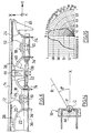
- the light emitting diodes are optical systems consisting of a P chip generating light flux, a mirror M to collect and redirect the flow emitted towards the rear, and a hemispherical condenser C to concentrate the flow emitted forwards.
- the diode emits a beam light angularly limited and whose maximum intensity is located in the X axis of this diode, according to a program indicator shown in Figure 15.
- the left half of Figure 15 represents the half-indicator of emission of the diode 10, plotting the values of the angular aperture on the x-axis and the values of the relative intensity of the light beam.
- the right half of Figure 15 represents a half emission lobe in polar coordinates, carrying the intensity values on the rays relative of the light beam, and in angular coordinates the values of the angular aperture of the light beam.
- the values indicated, expressed in candelas by degrees, correspond to a horizontal section of the beam on a screen perpendicular to the X axis and to a determined distance from the diode. The beam trace on this screen forms a circular spot of revolution.
- the windscreen 12 is formed on its inner face with streaks 16, generally circular in shape, and whose shape in vertical section corresponds to that of a cylindrical Fresnel lens. These streaks 16 are able to straighten the light rays emitted by light-emitting diode 10 upwards and downwards so that they propagate in a generally horizontal direction. These streaks have no influence on the horizontal distribution of light rays.
- the streaks 18 formed on the surface exterior of the windscreen 12 ensure a horizontal distribution of the light rays in the direction of plate 14, so that the illumination of the fire in direction Y throughout of the illuminating surface is constant.
- the ridges 20 formed on the plate 14 deflect the light rays from the windscreen 12 to direct them in a substantially parallel direction to direction X.
- the distribution functions F ( ⁇ ) taken into account in the calculation of the streaks 18 formed on the external surface of the windscreen 12 are defined and optimized as a function of the emission indicator I ( ⁇ ) of the light-emitting diode used, each type of light-emitting diode having a specific emission indicator I ( ⁇ ).
- y k 1 ( ⁇ ) * k 2 ( ⁇ ) * k 3 ( ⁇ ) * ⁇
- y is the abscissa of a current point of the plate (14) in the direction Y
- k 1 ( ⁇ ) is the desired law of evolution of the illumination of the fire as a function of the coordinate (y) on the plate (14)
- k 2 ( ⁇ ) is the emission law ( I ( ⁇ )) of the light source
- k 3 ( ⁇ ) is the law of evolution of the transmission coefficients
- ⁇ is an angle made by a light ray coming from the light source (10) with respect to the general direction of emission (X).
- Yet another advantage of the present invention is that, in this way, it is possible to use in the best conditions, a reduced number of diodes electroluminescent, for example three or four, while the traffic lights of the prior art used a much higher number.
- the diodes electroluminescent must conventionally be grouped electrically in series by a multiple of three or four diodes, which led to assemblies comprising up to sixty four diodes.
- such arrangements have as a disadvantage a relatively high operating temperature, detrimental to efficiency diodes.
- the design of the optical structure according to the present invention it is possible to use only a minimum number of light-emitting diodes.
- Such a montage of three or four diodes in series is practically insensitive to variations in supply voltage, and practically all the electrical energy consumed is transformed into luminous flux, and very little heat by the Joule effect.
- the optical structure makes it possible to produce a signaling light having a large width in direction Y, for example of the order of 300 mm, a relatively small height in the Z direction, for example of the order of 10 mm, and a shallow depth in the direction X, for example of the order of 30 mm, the diodes being spaced about 75 mm apart.
- the fact of spacing the diodes makes it possible to limit the internal heating of the case to a minimum value, which allows the diodes to be used within their optimal operating range. Indeed, the efficiency of a light emitting diode, characterizing the amount of light emitted in relation to the absorbed electrical energy, degrades as the temperature of the light emitting chip rises.
- the invention by moving the diodes away from each other others, allows the diodes to operate optimally, the heating effects mutual between two contiguous diodes being reduced to a large extent. This is how we will be able to use diodes emitting a strong luminous flux without that they undergo a self-heating phenomenon and supplying them at full power at their nominal voltage, without affecting their lifespan.
- CMS surface mounting
- the outlet plate can be straight or have a fixed or variable radius of curvature.
Landscapes
- Engineering & Computer Science (AREA)
- General Engineering & Computer Science (AREA)
- Physics & Mathematics (AREA)
- Microelectronics & Electronic Packaging (AREA)
- Optics & Photonics (AREA)
- Mechanical Engineering (AREA)
- Non-Portable Lighting Devices Or Systems Thereof (AREA)
- Lighting Device Outwards From Vehicle And Optical Signal (AREA)
- Illuminated Signs And Luminous Advertising (AREA)
Abstract
Description
- la structure optique comporte en outre, entre les éléments de liaison et les deuxièmes éléments, des éléments de jonction qui sont d'une seule pièce avec ceux-ci,
- le deuxième élément en forme de plaque comporte tout le long de l'un de ses bords longitudinaux une nervure de rigidification,
- la structure optique comporte, entre le deuxième élément et les premiers éléments ou les éléments de liaison, un plateau continu qui est d'une seule pièce avec ces éléments,
- la structure optique comporte des éléments de fixation d'un circuit imprimé,
- le circuit imprimé porte les sources lumineuses,
- les sources lumineuses sont des diodes électroluminescentes,
- les sources lumineuses sont essentiellement alignées,
- la structure optique comporte des moyens de retenue d'un connecteur associé au circuit imprimé, ces moyens e retenue étant d'une seule pièce avec la structure optique,
- la structure optique comporte des moyens de fixation dans un boítier, qui sont d'une seule pièce avec la structure optique, et
- le premier élément répartit la lumière sur le deuxième élément en tenant compte des variations des coefficients de transmission des premier et deuxième éléments, et de la courbe indicatrice d'émission de la source lumineuse, pour obtenir un éclairement en sortie du deuxième élément qui réponde à une loi prédéterminée.
- établir une loi d'évolution des coefficients de transmission des moyens de traitement optique en fonction d'au moins une coordonnée sur la plaque dans une direction perpendiculaire à la direction générale d'émission,
- établir une loi souhaitée d'évolution de l'éclairement du feu en fonction de la coordonnée sur la plaque.
- déterminer la courbe indicatrice d'émission de la source lumineuse et la loi d'émission correspondante,
- établir par combinaison de ces lois une relation entre l'orientation d'un rayon issu de la source lumineuse et incident sur le deuxième élément et la coordonnée sur la plaque,
- définir la géométrie des moyens de traitement optique en fonction de ladite relation,
- fabriquer en utilisant ladite géométrie un moule pour au moins le premier élément,
- mouler le premier élément à l'aide dudit moule.
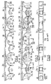
- La Figure 1 représente une vue en perspective de trois quarts arrière d'un feu de signalisation réalisé selon la présente invention ;
- La Figure 2 représente une vue en perspective de trois quarts avant du feu de signalisation de la Figure 1 ;
- La Figure 3 représente une vue de dessus du feu de la Figure 1 ;
- La Figure 4 représente une vue analogue à celle de la Figure 3, le feu étant dépourvu de circuit électrique ;
- La Figure 5 représente une vue par l'arrière du feu de la Figure 4 ;
- La Figure 6 représente une vue de dessus à plus grande échelle d'une extrémité du feu de la Figure 3 ;
- La Figure 7 représente une vue de dessus d'une variante de réalisation du feu des Figures 1 à 6;
- La Figure 8 représente une vue de côté du feu des Figures 1 à 6 ou de la Figure 7, par exemple vue dans la direction VIII des Figures 5 et 7 ;
- La Figure 9 représente une vue en coupe selon la ligne IX-IX de la Figure 3 ;
- La Figure 10 représente une vue en coupe selon la ligne X-X de la Figure 3 ;
- La Figure 11 représente une vue en coupe selon la ligne XI-XI de la Figure 3 ;
- La Figure 12 représente une vue en coupe selon la ligne XII-XII de la Figure 7 ;
- La Figure 13 représente une vue en coupe selon la ligne XIII-XIII de la Figure 7 ;
- La Figure 14 représente une vue en coupe schématique d'une diode électroluminescente, et
- La Figure 15 représente un diagramme d'émission d'une diode électroluminescente.
l'angle que fait un rayon émis par la diode électroluminescente 10 avec la direction X.
- établir une loi d'évolution k 3 () des coefficients de transmission des moyens de traitement optique 16, 18, 20 en fonction d'au moins une coordonnée y sur la plaque 14 dans une direction Y perpendiculaire à la direction générale d'émission X
- établir une loi souhaitée k 1 () d'évolution de l'éclairement du feu en fonction de la coordonnée y sur la plaque 14,
- déterminer la courbe k 2 () indicatrice d'émission de la source lumineuse 10 et la loi d'émission I() correspondante,
- établir par combinaison de ces lois une relation entre l'orientation d'un rayon issu de la source lumineuse 10 et incident sur le deuxième élément 14, 20 et la coordonnée y sur la plaque 14,
- définir la géométrie des moyens de traitement optique 16, 18, 20 en fonction de ladite relation,
- fabriquer en utilisant ladite géométrie un moule pour au moins le premier élément 12, 6, 18,
- mouler le premier élément 12, 16, 18 à l'aide dudit moule.
k 1() est la loi souhaitée d'évolution de l'éclairement du feu en fonction de la coordonnée (y) sur la plaque (14),
k2 () est la loi d'émission (I()) de la source lumineuse,
k 3() est la loi d'évolution des coefficients de transmission, et
est un angle que fait un rayon lumineux issu de la source lumineuse (10) par rapport à la direction générale d'émission (X).
Claims (11)
- Feu de signalisation pour véhicule automobile comprenant une pluralité de sources lumineuses (10) et des moyens de traitement optique (16, 18, 20) aptes à redresser la lumière émise par les sources lumineuses (10) pour qu'elle se propage dans une direction essentiellement parallèle à une direction générale d'émission (X), les moyens de traitement optique (16, 18, 20) comprenant, en association avec chaque source (10), un premier élément (12, 16, 18) apte à répartir la lumière dans un plan (YZ) essentiellement perpendiculaire à la direction générale d'émission (X), de façon essentiellement homogène sur un deuxième élément (14, 20) en forme générale de plaque et apte à redresser la lumière incidente vers ladite direction générale d'émission (X), caractérisé en ce que des éléments de liaison (22, 24) sont disposés entre des premiers éléments (12) adjacents et entre les premiers éléments (12) et le deuxième élément (14), et en ce que le premier élément (12), le deuxième élément (14) et les éléments de liaison (22, 24) sont venus de matière ensemble et forment une structure optique d'une seule pièce.
- Feu de signalisation selon la revendication 1, caractérisé en ce que la structure optique comporte en outre, entre les éléments de liaison (22) et les deuxièmes éléments (14), des éléments de jonction (28) qui sont d'une seule pièce avec ceux-ci.
- Feu de signalisation selon la revendication 1, caractérisé en ce que le deuxième élément en forme de plaque (14) comporte tout le long de l'un de ses bords longitudinaux une nervure (26) de rigidification.
- Feu de signalisation selon la revendication 1, caractérisé en ce que la structure optique comporte, entre le deuxième élément (14) et les premiers éléments (12) ou les éléments de liaison (22, 24), un plateau continu (32) qui est d'une seule pièce avec ces éléments (12, 14, 22, 24).
- Feu de signalisation selon la revendication 1, caractérisé en ce que la structure optique comporte des éléments de fixation (34) d'un circuit imprimé (36).
- Feu de signalisation selon la revendication 5, caractérisé en ce que le circuit imprimé (36) porte les sources lumineuses (10).
- Feu de signalisation selon la revendication 6, caractérisé en ce que les sources lumineuses (10) sont des diodes électroluminescentes.
- Feu de signalisation selon la revendication 7, caractérisé en ce que les sources lumineuses sont essentiellement alignées.
- Feu de signalisation selon la revendication 5, caractérisé en ce que la structure optique comporte des moyens de retenue (40, 44) d'un connecteur (42) associé au circuit imprimé (36), ces moyens e retenue étant d'une seule pièce avec la structure optique.
- Feu de signalisation selon la revendication 1, caractérisé en ce que la structure optique comporte des moyens de fixation (46) dans un boítier, qui sont d'une seule pièce avec la structure optique.
- Feu de signalisation selon la revendication 1, caractérisé en ce que le premier élément (12, 16, 18) répartit la lumière sur le deuxième élément en tenant compte des variations (k 3 ()) des coefficients de transmission des premier (12) et deuxième (14) éléments, et de la courbe indicatrice d'émission (k 2 ()) de la source lumineuse (10), pour obtenir un éclairement en sortie du deuxième élément (14) qui réponde à une loi prédéterminée (k 1 ()).
Applications Claiming Priority (2)
| Application Number | Priority Date | Filing Date | Title |
|---|---|---|---|
| FR0011003A FR2813379B1 (fr) | 2000-08-28 | 2000-08-28 | Feu de signalisation a structure optique simplifiee |
| FR0011003 | 2000-08-28 |
Publications (2)
| Publication Number | Publication Date |
|---|---|
| EP1184618A1 true EP1184618A1 (fr) | 2002-03-06 |
| EP1184618B1 EP1184618B1 (fr) | 2008-09-10 |
Family
ID=8853771
Family Applications (1)
| Application Number | Title | Priority Date | Filing Date |
|---|---|---|---|
| EP01401780A Expired - Lifetime EP1184618B1 (fr) | 2000-08-28 | 2001-07-04 | Feu de signalisation à structure optique simplifée et procédé de fabrication d'une telle structure |
Country Status (7)
| Country | Link |
|---|---|
| US (1) | US6783268B2 (fr) |
| EP (1) | EP1184618B1 (fr) |
| JP (1) | JP4942886B2 (fr) |
| CN (1) | CN1243925C (fr) |
| DE (1) | DE60135715D1 (fr) |
| ES (1) | ES2313936T3 (fr) |
| FR (1) | FR2813379B1 (fr) |
Cited By (4)
| Publication number | Priority date | Publication date | Assignee | Title |
|---|---|---|---|---|
| DE10341431A1 (de) * | 2003-09-09 | 2005-03-31 | Hella Kgaa Hueck & Co. | Fahrzeugleuchte |
| EP1413823A3 (fr) * | 2002-10-22 | 2006-12-20 | Valeo Sylvania L.L.C. | Appareil d'éclairage, dispositif de lampe et de lentille et boîtier de lampe |
| DE102005031777A1 (de) * | 2005-07-07 | 2007-01-18 | Hella Kgaa Hueck & Co. | Signalleuchte für Fahrzeuge |
| FR3141231A1 (fr) * | 2022-10-25 | 2024-04-26 | Valeo Vision | Module optique pour un dispositif lumineux de signalisation |
Families Citing this family (17)
| Publication number | Priority date | Publication date | Assignee | Title |
|---|---|---|---|---|
| FR2844579B1 (fr) | 2002-09-12 | 2005-05-27 | Valeo Vision | Module de positionnement et d'alimentation de diode electroluminescente |
| FR2853392B1 (fr) * | 2003-04-04 | 2006-06-16 | Sli Miniature Lighting Sa | Feu arriere, en particulier feu stop pour vehicule automobile |
| GB2400905A (en) * | 2003-04-24 | 2004-10-27 | Memco Ltd | Edge device for a powered door with infra-red and visible elements |
| US9464767B2 (en) * | 2004-03-18 | 2016-10-11 | Cliplight Holdings, Ltd. | LED work light |
| US7044620B2 (en) * | 2004-04-30 | 2006-05-16 | Guide Corporation | LED assembly with reverse circuit board |
| FR2870083B1 (fr) | 2004-05-10 | 2006-07-14 | Sli Miniature Lighting Sa Sa | Dispositif de maintien et de connexion de composants optoelectroniques comme les leds du type plcc2 et plcc4 |
| AT504577B1 (de) * | 2006-11-24 | 2009-06-15 | Zizala Lichtsysteme Gmbh | Led-lichtquellensystem |
| US20090086499A1 (en) * | 2007-09-27 | 2009-04-02 | Lin Rocky Yi-Ping | Car spoiler having light-emitting effect |
| JP2009176488A (ja) * | 2008-01-22 | 2009-08-06 | Kanto Auto Works Ltd | 車両用灯具 |
| CZ306888B6 (cs) * | 2010-08-06 | 2017-08-30 | Varroc Lighting Systems, s.r.o. | Světlovodicí modul |
| EP3138734B1 (fr) * | 2015-09-03 | 2020-04-15 | SMR Patents S.à.r.l. | Module lumineux, ensemble lumineux et dispositif de rétrovision pour véhicule |
| DE102012107676B4 (de) * | 2012-08-21 | 2016-04-14 | Truck-Lite Europe Gmbh | Optikkörper für eine Fahrzeugleuchte |
| US20140092596A1 (en) * | 2012-09-28 | 2014-04-03 | Linear Lighting Corp. | Dimmable, high-efficiency led linear lighting system with interchangeable features and methods for producing same |
| CZ307945B6 (cs) * | 2018-01-08 | 2019-09-04 | Hella Autotechnik Nova S.R.O. | Prostředek pro zajištění homogenity světelného svazku |
| CN219775586U (zh) * | 2023-02-27 | 2023-09-29 | 法雷奥市光(中国)车灯有限公司 | 照明装置和机动车辆 |
| DE202023106606U1 (de) * | 2023-11-10 | 2023-12-15 | Aspöck Systems GmbH | Signalleuchte für Fahrzeuge |
| CN120176047A (zh) * | 2023-12-18 | 2025-06-20 | 法雷奥照明公司 | 灯组件、制备灯组件的方法以及机动车辆 |
Citations (4)
| Publication number | Priority date | Publication date | Assignee | Title |
|---|---|---|---|---|
| FR2207473A5 (en) * | 1972-11-22 | 1974-06-14 | Tecalemit Sa | Socket and cover for automobile lights - formed from a single plastics piece by extrusion and blow-moulding |
| US4733335A (en) * | 1984-12-28 | 1988-03-22 | Koito Manufacturing Co., Ltd. | Vehicular lamp |
| FR2614969A1 (fr) | 1987-05-07 | 1988-11-10 | Cibie Projecteurs | Feu de signalisation a grande plage eclairante et luminance homogene, notamment pour vehicule automobile |
| FR2776595A1 (fr) | 1998-03-31 | 1999-10-01 | Valeo Vision | Feu de signalisation comprenant plusieurs sources lumineuses |
Family Cites Families (4)
| Publication number | Priority date | Publication date | Assignee | Title |
|---|---|---|---|---|
| JPS61116702A (ja) * | 1984-11-12 | 1986-06-04 | 株式会社小糸製作所 | 車輛用灯具 |
| US4859043A (en) | 1987-05-07 | 1989-08-22 | Cibie Projecteurs | High efficiency signal light, in particular for a motor vehicle |
| FR2707223B1 (fr) * | 1993-07-07 | 1995-09-29 | Valeo Vision | Feu de signalisation perfectionné à diodes électroluminescentes. |
| JPH10223011A (ja) * | 1997-02-10 | 1998-08-21 | Koito Mfg Co Ltd | 車輌用灯具 |
-
2000
- 2000-08-28 FR FR0011003A patent/FR2813379B1/fr not_active Expired - Lifetime
-
2001
- 2001-07-04 EP EP01401780A patent/EP1184618B1/fr not_active Expired - Lifetime
- 2001-07-04 DE DE60135715T patent/DE60135715D1/de not_active Expired - Lifetime
- 2001-07-04 ES ES01401780T patent/ES2313936T3/es not_active Expired - Lifetime
- 2001-08-24 CN CNB011258055A patent/CN1243925C/zh not_active Expired - Lifetime
- 2001-08-28 JP JP2001257654A patent/JP4942886B2/ja not_active Expired - Fee Related
- 2001-08-28 US US09/940,981 patent/US6783268B2/en not_active Expired - Lifetime
Patent Citations (4)
| Publication number | Priority date | Publication date | Assignee | Title |
|---|---|---|---|---|
| FR2207473A5 (en) * | 1972-11-22 | 1974-06-14 | Tecalemit Sa | Socket and cover for automobile lights - formed from a single plastics piece by extrusion and blow-moulding |
| US4733335A (en) * | 1984-12-28 | 1988-03-22 | Koito Manufacturing Co., Ltd. | Vehicular lamp |
| FR2614969A1 (fr) | 1987-05-07 | 1988-11-10 | Cibie Projecteurs | Feu de signalisation a grande plage eclairante et luminance homogene, notamment pour vehicule automobile |
| FR2776595A1 (fr) | 1998-03-31 | 1999-10-01 | Valeo Vision | Feu de signalisation comprenant plusieurs sources lumineuses |
Cited By (6)
| Publication number | Priority date | Publication date | Assignee | Title |
|---|---|---|---|---|
| EP1413823A3 (fr) * | 2002-10-22 | 2006-12-20 | Valeo Sylvania L.L.C. | Appareil d'éclairage, dispositif de lampe et de lentille et boîtier de lampe |
| DE10341431A1 (de) * | 2003-09-09 | 2005-03-31 | Hella Kgaa Hueck & Co. | Fahrzeugleuchte |
| DE102005031777A1 (de) * | 2005-07-07 | 2007-01-18 | Hella Kgaa Hueck & Co. | Signalleuchte für Fahrzeuge |
| DE102005031777B4 (de) * | 2005-07-07 | 2021-03-11 | HELLA GmbH & Co. KGaA | Signalleuchte für Fahrzeuge mit einem gekrümmten Optikelement, das versetzte Prismen aufweist |
| FR3141231A1 (fr) * | 2022-10-25 | 2024-04-26 | Valeo Vision | Module optique pour un dispositif lumineux de signalisation |
| WO2024088832A1 (fr) * | 2022-10-25 | 2024-05-02 | Valeo Vision | Module optique pour un dispositif lumineux de signalisation pour vehicules automobiles |
Also Published As
| Publication number | Publication date |
|---|---|
| US6783268B2 (en) | 2004-08-31 |
| US20030123260A1 (en) | 2003-07-03 |
| FR2813379A1 (fr) | 2002-03-01 |
| DE60135715D1 (de) | 2008-10-23 |
| EP1184618B1 (fr) | 2008-09-10 |
| JP2002140908A (ja) | 2002-05-17 |
| FR2813379B1 (fr) | 2002-11-29 |
| ES2313936T3 (es) | 2009-03-16 |
| CN1243925C (zh) | 2006-03-01 |
| JP4942886B2 (ja) | 2012-05-30 |
| CN1340675A (zh) | 2002-03-20 |
Similar Documents
| Publication | Publication Date | Title |
|---|---|---|
| EP1184618B1 (fr) | Feu de signalisation à structure optique simplifée et procédé de fabrication d'une telle structure | |
| EP1746339B1 (fr) | Dispositif d'éclairage ou de signalisation, notamment pour véhicule automobile | |
| EP3067618B1 (fr) | Dispositif lumineux a guides optiques | |
| EP3390900B1 (fr) | Module lumineux, notamment pour feu stop de véhicule | |
| FR2865524A1 (fr) | Unite d'eclairage a diode electroluminescente pour phare de vehicule | |
| EP0762049B1 (fr) | Feu de signalisation à plusieurs sources alignées, notamment feu stop complémentaire pour véhicule automobile | |
| FR2828727A1 (fr) | Lampe de vehicule a diodes photoemissives | |
| FR3103877A1 (fr) | Elément optique et module lumineux d’un véhicule automobile équipé d’un tel élément optique | |
| EP4579123A2 (fr) | Module lumineux pour l'éclairage d'un véhicule automobile | |
| FR2680862A1 (fr) | Feu de signalisation a elements electroluminescents, notamment pour vehicule automobile. | |
| EP3357752B1 (fr) | Module d'éclairage d'un faisceau lumineux pour projecteur de véhicule automobile | |
| FR2943400A1 (fr) | Dispositif d'eclairage ou de signalisation pour vehicule automobile | |
| EP3884206B1 (fr) | Module lumineux multifonctions doté de deux guides de lumière de type plat | |
| FR3062460A1 (fr) | Module lumineux pour projecteur de vehicule | |
| FR2853393A1 (fr) | Phare de vehicule a diode photoemissive | |
| EP2101202A1 (fr) | Dispositif de signalisation lumineuse pour cycle | |
| WO2023031341A1 (fr) | Dispositif lumineux d'un véhicule automobile | |
| WO2016124718A1 (fr) | Module lumineux d'un véhicule compatible au trafic gauche et au trafic droit | |
| FR3142531A1 (fr) | dispositif lumineux pour véhicule automobile | |
| FR3106651A1 (fr) | Guide de lumière plat pour module lumineux de signalisation de véhicule automobile | |
| WO2017121944A1 (fr) | Bloc optique comprenant un feu de signalisation doté d'un guide de lumière plat saillant de sa glace extérieure | |
| EP0838628B1 (fr) | Projecteur à conduit de lumière pour véhicules automobiles | |
| FR3015002A1 (fr) | Dispositif d'eclairage | |
| FR3038695A1 (fr) | Module lumineux pour l'eclairage et/ou la signalisation d'un vehicule automobile | |
| EP3486554B1 (fr) | Module lumineux pour projecteur de vehicule |
Legal Events
| Date | Code | Title | Description |
|---|---|---|---|
| PUAI | Public reference made under article 153(3) epc to a published international application that has entered the european phase |
Free format text: ORIGINAL CODE: 0009012 |
|
| AK | Designated contracting states |
Kind code of ref document: A1 Designated state(s): AT BE CH CY DE DK ES FI FR GB GR IE IT LI LU MC NL PT SE TR Kind code of ref document: A1 Designated state(s): DE ES GB IT |
|
| AX | Request for extension of the european patent |
Free format text: AL;LT;LV;MK;RO;SI |
|
| 17P | Request for examination filed |
Effective date: 20020321 |
|
| AKX | Designation fees paid |
Free format text: DE ES GB IT |
|
| GRAP | Despatch of communication of intention to grant a patent |
Free format text: ORIGINAL CODE: EPIDOSNIGR1 |
|
| GRAS | Grant fee paid |
Free format text: ORIGINAL CODE: EPIDOSNIGR3 |
|
| GRAA | (expected) grant |
Free format text: ORIGINAL CODE: 0009210 |
|
| AK | Designated contracting states |
Kind code of ref document: B1 Designated state(s): DE ES GB IT |
|
| REG | Reference to a national code |
Ref country code: GB Ref legal event code: FG4D Free format text: NOT ENGLISH |
|
| REF | Corresponds to: |
Ref document number: 60135715 Country of ref document: DE Date of ref document: 20081023 Kind code of ref document: P |
|
| REG | Reference to a national code |
Ref country code: ES Ref legal event code: FG2A Ref document number: 2313936 Country of ref document: ES Kind code of ref document: T3 |
|
| PLBE | No opposition filed within time limit |
Free format text: ORIGINAL CODE: 0009261 |
|
| STAA | Information on the status of an ep patent application or granted ep patent |
Free format text: STATUS: NO OPPOSITION FILED WITHIN TIME LIMIT |
|
| 26N | No opposition filed |
Effective date: 20090611 |
|
| GBPC | Gb: european patent ceased through non-payment of renewal fee |
Effective date: 20090704 |
|
| PG25 | Lapsed in a contracting state [announced via postgrant information from national office to epo] |
Ref country code: GB Free format text: LAPSE BECAUSE OF NON-PAYMENT OF DUE FEES Effective date: 20090704 |
|
| REG | Reference to a national code |
Ref country code: DE Ref legal event code: R079 Ref document number: 60135715 Country of ref document: DE Free format text: PREVIOUS MAIN CLASS: F21S0008100000 Ipc: F21S0043000000 |
|
| PGFP | Annual fee paid to national office [announced via postgrant information from national office to epo] |
Ref country code: DE Payment date: 20200716 Year of fee payment: 20 Ref country code: ES Payment date: 20200817 Year of fee payment: 20 |
|
| PGFP | Annual fee paid to national office [announced via postgrant information from national office to epo] |
Ref country code: IT Payment date: 20200710 Year of fee payment: 20 |
|
| REG | Reference to a national code |
Ref country code: DE Ref legal event code: R071 Ref document number: 60135715 Country of ref document: DE |
|
| REG | Reference to a national code |
Ref country code: ES Ref legal event code: FD2A Effective date: 20211013 |
|
| PG25 | Lapsed in a contracting state [announced via postgrant information from national office to epo] |
Ref country code: ES Free format text: LAPSE BECAUSE OF EXPIRATION OF PROTECTION Effective date: 20210705 |