EP1184114A2 - Hole forming tool - Google Patents
Hole forming tool Download PDFInfo
- Publication number
- EP1184114A2 EP1184114A2 EP01107731A EP01107731A EP1184114A2 EP 1184114 A2 EP1184114 A2 EP 1184114A2 EP 01107731 A EP01107731 A EP 01107731A EP 01107731 A EP01107731 A EP 01107731A EP 1184114 A2 EP1184114 A2 EP 1184114A2
- Authority
- EP
- European Patent Office
- Prior art keywords
- hole forming
- forming tool
- range
- chip discharging
- cutting edges
- Prior art date
- Legal status (The legal status is an assumption and is not a legal conclusion. Google has not performed a legal analysis and makes no representation as to the accuracy of the status listed.)
- Granted
Links
Images


Classifications
-
- C—CHEMISTRY; METALLURGY
- C22—METALLURGY; FERROUS OR NON-FERROUS ALLOYS; TREATMENT OF ALLOYS OR NON-FERROUS METALS
- C22C—ALLOYS
- C22C29/00—Alloys based on carbides, oxides, nitrides, borides, or silicides, e.g. cermets, or other metal compounds, e.g. oxynitrides, sulfides
- C22C29/02—Alloys based on carbides, oxides, nitrides, borides, or silicides, e.g. cermets, or other metal compounds, e.g. oxynitrides, sulfides based on carbides or carbonitrides
- C22C29/06—Alloys based on carbides, oxides, nitrides, borides, or silicides, e.g. cermets, or other metal compounds, e.g. oxynitrides, sulfides based on carbides or carbonitrides based on carbides, but not containing other metal compounds
- C22C29/08—Alloys based on carbides, oxides, nitrides, borides, or silicides, e.g. cermets, or other metal compounds, e.g. oxynitrides, sulfides based on carbides or carbonitrides based on carbides, but not containing other metal compounds based on tungsten carbide
-
- B—PERFORMING OPERATIONS; TRANSPORTING
- B23—MACHINE TOOLS; METAL-WORKING NOT OTHERWISE PROVIDED FOR
- B23B—TURNING; BORING
- B23B51/00—Tools for drilling machines
- B23B51/02—Twist drills
-
- B—PERFORMING OPERATIONS; TRANSPORTING
- B22—CASTING; POWDER METALLURGY
- B22F—WORKING METALLIC POWDER; MANUFACTURE OF ARTICLES FROM METALLIC POWDER; MAKING METALLIC POWDER; APPARATUS OR DEVICES SPECIALLY ADAPTED FOR METALLIC POWDER
- B22F5/00—Manufacture of workpieces or articles from metallic powder characterised by the special shape of the product
- B22F2005/001—Cutting tools, earth boring or grinding tool other than table ware
-
- B—PERFORMING OPERATIONS; TRANSPORTING
- B23—MACHINE TOOLS; METAL-WORKING NOT OTHERWISE PROVIDED FOR
- B23B—TURNING; BORING
- B23B2251/00—Details of tools for drilling machines
- B23B2251/18—Configuration of the drill point
-
- Y—GENERAL TAGGING OF NEW TECHNOLOGICAL DEVELOPMENTS; GENERAL TAGGING OF CROSS-SECTIONAL TECHNOLOGIES SPANNING OVER SEVERAL SECTIONS OF THE IPC; TECHNICAL SUBJECTS COVERED BY FORMER USPC CROSS-REFERENCE ART COLLECTIONS [XRACs] AND DIGESTS
- Y10—TECHNICAL SUBJECTS COVERED BY FORMER USPC
- Y10T—TECHNICAL SUBJECTS COVERED BY FORMER US CLASSIFICATION
- Y10T408/00—Cutting by use of rotating axially moving tool
- Y10T408/78—Tool of specific diverse material
-
- Y—GENERAL TAGGING OF NEW TECHNOLOGICAL DEVELOPMENTS; GENERAL TAGGING OF CROSS-SECTIONAL TECHNOLOGIES SPANNING OVER SEVERAL SECTIONS OF THE IPC; TECHNICAL SUBJECTS COVERED BY FORMER USPC CROSS-REFERENCE ART COLLECTIONS [XRACs] AND DIGESTS
- Y10—TECHNICAL SUBJECTS COVERED BY FORMER USPC
- Y10T—TECHNICAL SUBJECTS COVERED BY FORMER US CLASSIFICATION
- Y10T408/00—Cutting by use of rotating axially moving tool
- Y10T408/89—Tool or Tool with support
- Y10T408/909—Having peripherally spaced cutting edges
- Y10T408/9095—Having peripherally spaced cutting edges with axially extending relief channel
- Y10T408/9097—Spiral channel
Definitions
- the present invention relates to hole forming tools such as drills, etc., suitable for forming holes in hard steels of which the hardness is, for example, higher than 40HRC.
- drills according to the above-described publications are designed such that a helix angle of chip discharging grooves is small, such as 10° to 20°, while a helix angle of drills for typical steels is approximately 20° to 30°.
- the drills are designed such that a core diameter is larger than 0.3D, in which D represents the outside diameter of the drills.
- a hole formed by the above-described drills for hard steels will be a primary hole. Accordingly, in addition to the maintenance of the tool life, high cutting accuracy is also required.
- the above-described drills are designed merely for increasing the rigidity thereof by decreasing the helix angle of the chip discharging grooves and by increasing the core diameter. Although such a construction reduces the risk of causing fracture of the cutting edges or breakage of the drills, there is a disadvantage in that the cutting force is increased and the sharpness of the cutting edges is degraded. As a result, the cutting accuracy is degraded.
- a hole forming tool which rotates around a rotational axis includes: one or more chip discharging grooves which are helically formed around the rotational axis in the exterior surface of the hole forming tool; and one or more cutting edges which are formed along ridge lines between inner surfaces of the chip discharging grooves, which are facing the rotating direction, and flank faces formed at an end of the hole forming tool.
- a radial rake angle of the cutting edges is set to a negative value in the range of -5° to -10°, and a point angle is in the range of 125° to 135°.
- the radial rake angle of the cutting edges When the radial rake angle of the cutting edges is in the above-described range, the cutting force is reduced and fracture of the cutting edges is prevented. In addition, satisfactory sharpness of the cutting edges will be ensured.
- the value of the radial rake angle may be positive in a case of forming a hole in typical steels such as carbon steels, etc. However, in a case of cutting hard steels of which the hardness is, for example, over 40 HRC, fracture of cutting edges easily occurs when the value of the radial rake angle is higher than -5°. When the value of the radial rake angle is lower than -10°, the cutting force increases so that the cutting accuracy will be degraded.
- the point angle When the point angle is smaller than 125°, vibration easily occurs, especially in the case of cutting a hard steel. In addition. a time interval will be long in which the cutting edges are not completely led into a work material and in which the cutting is unstable. When the point angle is larger than 135°, the hole forming tool cannot smoothly penetrate into the work material. In either case, the fineness of the formed hole will be degraded.
- the point angle in the range of 125° to 135°, the time interval in which the cutting is unstable is reduced.
- the hole forming tool may smoothly penetrate into the work material. Accordingly, the degradation of the fineness of the formed hole is prevented.
- the hole forming tool may have one or more of the following characteristics.
- a groove width ratio of the hole forming tool is in the range of 0.9 to 1.1.
- the groove width ratio When the groove width ratio is smaller than 0.9, the chips will clump inside the chip discharging grooves due to the lack of space. When the groove width ratio is larger than 1.1, the rigidity of the hole forming tool will be reduced. In either case, the fineness of the formed hole will be degraded and breakage of the hole forming tool will occur.
- the groove width ratio in the range of 0.9 to 1.1, the clumping of the chips due to the lack of space is prevented, and sufficient rigidity of the hole forming tool is ensured. Accordingly, the fineness of the formed hole is maintained and breakage of the hole forming tool is prevented.
- a core diameter of the hole forming tool is in the range of 0.38D to 0.42D. in which D is a cutting edge diameter of the hole forming tool.
- the core diameter is smaller than 0.38D, the flexural rigidity of the tool will be insufficient, and when the core diameter is larger than 0.42D, the space inside the chip discharging grooves will be too small so that the chips will clump therein.
- the core diameter in the range of 0.38D to 0.42D, the flexural rigidity of the tool is ensured, and clumping of the chips, which increases the cutting force, is prevented. Accordingly, the fineness of the formed hole and the tool life are maintained.
- a helix angle of the chip discharging grooves may be in the range of 5° to 15°.
- the helix angle When the helix angle is smaller than 5°, the sharpness of the cutting edges and the ability to discharge the chips are degraded, so that fracture of the hole forming tool will occur. When the helix angle is larger than 15°, the torsional rigidity will be insufficient so that the fineness of the formed hole will be degraded.
- the helix angle in the range of 5° to 15°, fracture of the hole forming tool, which is caused by the degradations of the sharpness of the cutting edges and of the ability to discharge the chips, is prevented. In addition, sufficient torsional rigidity is ensured so that the fineness of the formed hole is maintained.
- the hole forming tool of the present invention is constructed of a cemented carbide, and an average particle diameter of WC, which is contained in the cemented carbide, may be in the rage of 0.1 to 1.0 ⁇ m.
- the radial rake angle may be set to a higher value, which improves the sharpness of the cutting edges.
- the toughness and the resistance to fracture of the hole forming tool are enhanced, so that the cutting accuracy and the tool life may be increased.
- At least a part including the chip discharging grooves of the hole forming tool is coated with a layer constructed of a hard material, for example, a titanium compound.
- the friction between the chips and the chip discharging grooves will be reduced, so that the load including cutting torque, thrust, etc., will also be reduced. As a result, the cutting edges will have further resistance to fracture and the tool life will be increased.
- the main body of said hole forming tool is constructed of a cemented carbide which comprises 10 ⁇ 2 wt% Co, 0.65 ⁇ 0.25 wt% Cr, WC for the balance, and inevitable impurities.
- the rigidity of the main body of the hole forming tool is ensured.
- the average particle diameter of WC is particularly small such as 0.1 to 1.0 ⁇ m, the versatility of shapes of the cutting edges will be increased. Accordingly, durability of the hole forming tool is ensured even when the radial rake angle is in the range of -5° to -10° , and fracture of the tool is prevented.
- the drill 1 has a shape of a rod and is constructed of a cemented carbide as described below.
- a main body 2 of the drill 1 includes a shank portion 3 and a cutting portion 4.
- Two chip discharging grooves 6 and 6 are helically formed in an exterior surface 4a of the cutting portion 4 in a rotationally symmetrical manner around a rotational axis O of the main body 2.
- cutting edges 8 and 8 are formed along ridge lines between inner surfaces 6a and 6a of the chip discharging grooves 6 and 6. which are facing the rotating direction, and an end surface 7 of the cutting portion 4.
- each of the cutting edges 8 and 8 includes a central portion 8a and a peripheral portion 8b.
- the central portion 8a has a shape of an approximately straight line and radially extends from the rotational axis O.
- the peripheral portion 8b also has a shape of an approximately straight line, and extends to the periphery of the cutting portion 4 in a manner such that the central portion 8a and the peripheral portion 8b form an obtuse angle.
- the central portion 8a and the peripheral portion 8b are smoothly connected, and the connecting part has a shape of an arc.
- the present invention is not limited to this.
- the central portion 8a and the peripheral portion 8b may also be angularly connected, forming an obtuse angle therebetween (for example, 150° to 170°).
- the end surface 7 of the cutting portion 4 has a pair of land portions 10 and 10 which are formed in a rotationally symmetrical manner.
- Each of the land portions 10 and 10 has a vertex at a point on which the rotational axis O crosses the end surface 7, and approaches the other end of the drill 1 toward the periphery of the end surface 7.
- Each of the land portions 10 and 10 form flank faces of the cutting edges 8, which includes a second flank face 11 and a third flank face 12.
- the second flank face is formed in the front region in the rotating direction, and has a positive and relatively small relief angle ⁇ 1.
- the third flank face 12 is formed in the rear region of the second flank face 11 in the rotating direction, and has a relatively large relief angle ⁇ 2 (> ⁇ 1).
- a thinning surface 13 is formed in the region still farther to the rear, and has a relief angle ⁇ 3 which is larger than ⁇ 2.
- flank faces in the end surface 7 are formed by planes including the second flank face 11 and the third flank face 12, as shown in Fig. 1.
- the present invention is not limited to this.
- a conical flank face, or flank faces having other adequate shapes may also be adopted.
- Each of the inner surfaces 6a and 6a at the ends of the chip discharging grooves 6 and 6 forms a rake surface of the peripheral portion 8b of the each of the cutting edges 8.
- a step surface 13a between the second flank face 11 in one land portion 10 and the thinning surface 13 in the other land portion 10 extends toward the shank portion 3 of the drill 1, forming a rake surface of the central portion 8a.
- the second flank faces 11 and 11 are protruding in the radial direction relative to the periphery of the third flank faces 12 and 12, forming margins 11a and 11a having a small width.
- the margins 11a and 11a extend along the chip discharging grooves 6 and 6 over the exterior surface 4a of the cutting portion 4.
- the maximum outside diameter (cutting edge diameter) D of the cutting portion 4 represents the distance between the peripheral ends of the cutting edges 8 and 8, which are at the front ends of the margins 11a and 11a in the rotating direction (see Fig. 1).
- La is a distance along an arc around the chips discharging groove 6, when the center of the arc is on the central axis.
- Lb is a distance along an arc at the periphery of the land portion 10.
- a groove width ratio La/Lb is in the range of 0.9 to 1.1. When the groove width ratio is smaller than 0.9, the width of the chip discharging grooves 6 and 6 will be too small, and the ability to discharge chips will be degraded. As a result, there will be a problem in that the chips will clump inside the chip discharging grooves 6 and 6. when the groove width ratio is larger than 1.1, the ability to discharge chips will be improved; however, the rigidity of the drill 1 will be reduced. In either case, there will be disadvantages in that the cutting accuracy will be degraded and the breakage of the drill 1 will easily occur.
- a diameter of a core 24 in the middle of the land portions 10 and 10 is in the range of 0.38D to 0.42D, in which D is the cutting edge diameter representing the distance between the peripheral ends of the cutting edges 8 and 8.
- D is the cutting edge diameter representing the distance between the peripheral ends of the cutting edges 8 and 8.
- the core diameter is smaller than 0.38D, the flexural rigidity of the main body 2 will be reduced.
- the core diameter is larger than 0.42D, the depth of the chip discharging grooves 6 and 6 will be small and the space therein will be insufficient, so that the chips will clump inside the chip discharging grooves 6 and 6. increasing the cutting force. As a result, fracture and wearing of the cutting edges 8 and 8 will occur. Accordingly, there will be problems in that the cutting accuracy will be degraded and the tool life will be reduced in either case.
- the chip discharging grooves 6 and 6 are helically formed around the rotational axis O in the inverse direction of the rotating direction toward the shank portion 3 of the main body.
- a helix angle ⁇ of the chip discharging grooves relative to the rotational axis O is in the range of 5° to 15°, when the drill is seen from the side.
- inclination of the chip discharging grooves 6 and 6 including the inner surfaces 6a and 6a. which form the rake surfaces will be too small. Thus, the sharpness of the cutting edges will be degraded.
- the helix angle ⁇ will be too small relative to the direction in which the chips are generated by the cutting edges 8 and 8, so that the ability to discharge the chips will also be degraded. Accordingly, the cutting force will be increased and fracture of the cutting edges 8 and 8 will easily occur.
- the helix angle ⁇ is larger than 15°, the torsional rigidity of the drill will be too small so that the cutting accuracy will be degraded, especially in the case of forming a hole in a hard steel.
- a point angle ⁇ between the lines extended from the cutting edges 8 and 8 in the end surface 7 of the main body 2 is in the range of 125° to 135°.
- the point angle ⁇ is smaller than 125°, vibration easily occurs during the hole forming process, especially in the case of cutting a hard steel.
- a time interval will be long in which the cutting edges 8 and 8 are not completely led into a work material, and in which the cutting is not stably performed.
- the point angle ⁇ is larger than 135°, the drill cannot smoothly penetrate into the work material. In either case, fineness of the formed hole will be degraded.
- a radial rake angle ⁇ is set to a negative value in a range of -5° to -10°, particularly at the peripheral portion 8b of the cutting edge 8.
- a radial rake angle ⁇ is higher than -5°, fracture of the cutting edges 8 and 8 will easily occur.
- the value of the radial rake angle ⁇ is lower than -10°, there will be a problem in that the accuracy of the hole position will be degraded due to the cutting force.
- At least the cutting edges 8 and 8 or the cutting portion 4 of the main body 2 are constructed of the cemented carbide, which preferably comprises 10 ⁇ 2 wt% Co, 0.65 ⁇ 0.25 wt% Cr tungsten carbide (WC) for the balance, and inevitable impurities.
- the average particle diameter of the tungsten carbide (WC), which is the main component of the cemented carbide. is in the range of 0.1 to 1.0 ⁇ m.
- the composition of the cemented carbide was 9% Co, 8.1% TiC, 9.9% TaC, 1.1% NbC, and WC for the balance.
- the average particle diameter of WC which is the main component of this cemented carbide, was in the range of approximately 2 to 3 ⁇ m.
- the value of the radial rake angle must be lower than -25° to avoid fracture of the cutting edges. Accordingly, since the value of the radial rake angle was set to such a low value, the sharpness of the cutting edges was not sufficient.
- the average particle diameter of WC is reduced, so that the radial rake angle may be set to a higher value, in the range of -5° to -10°. Accordingly, the sharpness of the cutting is improved. In addition, the versatility regarding the shape of the cutting edges is increased, and the resistance to fracture is maintained.
- the surface of the cutting portion 4 is coated with a layer 16, which is constructed of a hard material, for example a titanium compound. Accordingly, the resistances to fracture and to abrasion of the cutting edges 8 and 8 are enhanced. In addition, the cutting accuracy is improved and the tool life is increased.
- the performance of the drill 1, which has the above-described construction, is considered below in the case in which a hole is formed in a hard material of which the hardness after the heat treatment is higher than 40 HRC.
- the main body 2 of the drill 1 is rotated around the rotational axis O, and is moved toward the work material in the direction of the rotational axis O. Since the point angle ⁇ of the cutting portion 4 is in the range of 125° to 135°, the drill 1 smoothly penetrates into the work material.
- the rigidity of the drill is sufficient relative to the hardness of the work material. Accordingly, fracture of the cutting edges 8 and 8 is prevented.
- the average particle diameter of WC comprised in the cutting edges 8 and 8 is set to a small value such as 0.1 to 1.0 ⁇ m, and the radial rake angle ⁇ is set to a small and negative value such as -5° to -10°. Accordingly, fracture of the cutting edges 8 and 8 is prevented and the cutting force is reduced. In addition, the sharpness of the cutting edges 8 and 8 is ensured.
- the core diameter is in the range of 0.38D to 0.42D, the rigidity of the main body 2 is ensured and the space inside the chip discharging grooves 6 and 6 is sufficient.
- the work material is a hard die steel
- chips generated by the cutting edges 8 and 8 are crumbled into small pieces and do not elongate in a helical manner.
- the groove width ratio is in the range of 0.9 to 1.1.
- the fineness of the hole is ensured even when a shallow hole, in which L/D is 3 or smaller as in the conventional case, is formed in a hard steel of which the hardness is higher than 40 HRC. More specifically, a hole is formed in which the circularity is excellent, and in which the amount of oversizing and surface roughness is small. In addition, fracture of the cutting edges 8 and 8 is prevented, and the tool life is increased.
- the samples used in the cutting tests had basically the same construction as the drill 1 described above in the embodiment. As shown in Table 1, samples of types A and B were prepared as examples of the present invention, and samples of types C, D, and E were prepared as comparative examples.
- the material of the samples was Z10 according to ISO, which is a cemented carbide comprising 10 ⁇ 2 wt% Co, 0.65 ⁇ 0.25 wt% Cr, WC for the balance, and inevitable impurities.
- the average particle diameter of WC was 1.0 ⁇ m.
- values of the core diameter, the groove width ratio, the ratio radial rake angle ⁇ of the cutting edges 8 and 8, the point angle ⁇ , and the helix angle ⁇ are shown in Table 1.
- the material was M20 according to ISO, which is a cemented carbide comprising 9 wt% Co, 8.1 wt% TiC, 9.9 wt% TaC, 1.1 wt% NbC, and WC for the balance.
- the average particle diameter of WC was 2 ⁇ m.
- Other variables of the type C were the same as those of the type A.
- variables were the same as those of the type A except that the radial rake angle ⁇ was -15° and the point angle ⁇ was 120°.
- variables were the same as those of the type A except that the core diameter was 0.25D and the helix angle ⁇ was 30°.
- SKD11 according to the Japanese Industrial Standard (JIS). which is a cold die steel, was used after the heat treatment was performed.
- JIS Japanese Industrial Standard
- the hardness of the work material after the heat treatment was 60HRC.
- Material (ISO) Core diameter Groove width ratio Radial rake angle Point Angle Helix angle Type A (Examples) Z10 0.40D 1.0:1 -7° 130° 10°
- Type B Examples
- Type C Comparative Examples
- Type D Comparative Examples
- Type E Comparative Examples
- a first test differences in tool lives according to the material were examined.
- samples of the types A, B, and C were used for forming holes which penetrate through the work material.
- a soluble emulsion (10% dilution) was used as a cutting lubricant.
- holes were formed under conditions in which the feed was fixed to 0.10 mm/rev and the cutting speed was increased from 1 to 20 m/min, and amounts of oversizing in the formed holes were measured (see the upper section in the column “oversized” in Fig. 6).
- holes were formed under conditions in which the cutting speed was fixed to 20 m/min and the feed was increased to 0.10 mm/rev, and amounts of oversizing in the formed holes were measured (see the lower section in the column "oversize” in Fig. 6).
- holes were formed under conditions in which the feed was fixed to 0.10 mm/rev and the cutting speed was increased from 1 to 20 m/min, and surface roughnesses of the formed holes were measured (see the upper section in the column “surface roughness” in Fig. 6).
- holes were formed under conditions in which the cutting speed was fixed to 20 m/min and the feed was increased to 0.10 mm/rev, and surface roughnesses of the formed holes were measured (see the lower section in the column "surface roughness” in Fig. 6).
- holes were formed under conditions in which the feed was fixed to 0.10 mm/rev and the cutting speed was increased from 1 to 20 m/min, and circularities of the formed holes were measured (see the upper section in the column “circularity” in Fig. 6).
- holes were formed under conditions in which the cutting speed was fixed to 20 m/min and the feed was increased to 0.10 mm/rev, and circularities of the formed holes were measured (see the lower section in the column "circularity” in Fig. 6).
- the circularities of the holes formed by the samples of the type D were larger compared to the holes formed by the samples of the type A.
- the sample of the type D broke when the cutting speed was 20 m/min, as is understood from the upper section in Fig. 6.
- the sample of the type D broke when the feed was 0.10 mm/rev, as is understood from the lower section in Fig. 6.
- samples of the types A and E were used for forming holes which penetrate through the work material.
- SKD61 according to the Japanese Industrial Standard (JIS) was used as the work material.
- the hardness of the work material after the heat treatment was 50 HRC.
- the outside diameter D was 10 mm
- the cutting speed was 30 m/min.
- the feed was 0.10 mm/rev
- the soluble emulsion (10% dilution) was used as the cutting lubricant.
- the amount of abrasion in the sample of the type A after forming 100 holes (approximately 0.39 mm) and the amount of abrasion in the sample of the type E after forming 22 holes were approximately the same. At this time, normal abrasion was observed in the samples of both types, and the samples were not broken. The tool life of the sample of the type A was 3.5 times longer than that of the type E.
- the amounts of oversizing caused in the holes formed by the sample of the type A were significantly less compared to the holes formed by the sample of the type E. Although the sample of the type E broke after forming approximately 30 holes, the sample of the type A could form more than 100 holes.
- the drill 1 according to the embodiment of the present invention was a unitary type, the present invention is not limited to this.
- a drill of a brazed type, throwaway type, etc. may also be used as long as the cutting edges 8 and 8 are constructed of the cemented carbide having the above-described composition.
- the work material is not limited to hard steels.
- the present invention may also be applied in the process of forming a hole in a steel of which the hardness is 40 HRC or less.
- the present invention is not limited to drills, and may be applied in various hole forming tools.
Landscapes
- Engineering & Computer Science (AREA)
- Mechanical Engineering (AREA)
- Chemical & Material Sciences (AREA)
- Materials Engineering (AREA)
- Metallurgy (AREA)
- Organic Chemistry (AREA)
- Drilling Tools (AREA)
Abstract
Description
- The present invention relates to hole forming tools such as drills, etc., suitable for forming holes in hard steels of which the hardness is, for example, higher than 40HRC.
- This specification is on the basis of Japanese Patent Applications (Japanese Unexamined Patent Application Publication No. 11-244120, No. 2000-004058, No. 2000-093834, and No. 2000-099648), and the disclosures of these Japanese Patent Applications are incorporated herein as a part of this specification by reference.
- Conventionally, in a case of forming a hole in a die constructed of, for example a tool steel for cold dies, heat treatment was performed after the hole forming process. Accordingly, tools for typical steels were used. To satisfy a demand to reduce the period for processing and thereby reduce costs, however, a method in which the hole forming process is performed after the heat treatment has become increasingly common. In such a case, it is inefficient to form the hole by electrical discharge machining. Accordingly, drills for hard steels are used, which are capable of cutting hard steels of which the hardness is approximately 40 to 60 HRC, and 70 HRC at maximum.
- These drills have been used for forming shallow holes only, of which the ratio of the hole depth L and the outside diameter of the drills D, L/D, is 3 or less. Techniques for forming such holes are disclosed in, for example, Japanese Unexamined Patent Application Publications Nos. 7-80714 and 7-112311.
- With respect to conventional drills for hard steels of which the hardness exceeds 40 HRC, there has been a disadvantage in that wearing, chipping, and fracture of cutting edges easily occur. Thus, the cutting edges were quickly abraded and the tool life was reduced. To avoid this, drills according to the above-described publications are designed such that a helix angle of chip discharging grooves is small, such as 10° to 20°, while a helix angle of drills for typical steels is approximately 20° to 30°. Alternatively, the drills are designed such that a core diameter is larger than 0.3D, in which D represents the outside diameter of the drills. These designs may also be applied in combination. Accordingly, the rigidity of the drills is increased and the tool life is maintained.
- When, for example, finishing processing is to be performed after the hole forming process, a hole formed by the above-described drills for hard steels will be a primary hole. Accordingly, in addition to the maintenance of the tool life, high cutting accuracy is also required. The above-described drills, however, are designed merely for increasing the rigidity thereof by decreasing the helix angle of the chip discharging grooves and by increasing the core diameter. Although such a construction reduces the risk of causing fracture of the cutting edges or breakage of the drills, there is a disadvantage in that the cutting force is increased and the sharpness of the cutting edges is degraded. As a result, the cutting accuracy is degraded.
- Accordingly, in consideration of the above-described circumstances, it is an object of the present invention to provide a hole forming tool of which the tool life is increased without degrading the cutting accuracy.
- Basically, according to the present invention, a hole forming tool which rotates around a rotational axis includes: one or more chip discharging grooves which are helically formed around the rotational axis in the exterior surface of the hole forming tool; and one or more cutting edges which are formed along ridge lines between inner surfaces of the chip discharging grooves, which are facing the rotating direction, and flank faces formed at an end of the hole forming tool. In addition, a radial rake angle of the cutting edges is set to a negative value in the range of -5° to -10°, and a point angle is in the range of 125° to 135°.
- When the radial rake angle of the cutting edges is in the above-described range, the cutting force is reduced and fracture of the cutting edges is prevented. In addition, satisfactory sharpness of the cutting edges will be ensured. The value of the radial rake angle may be positive in a case of forming a hole in typical steels such as carbon steels, etc. However, in a case of cutting hard steels of which the hardness is, for example, over 40 HRC, fracture of cutting edges easily occurs when the value of the radial rake angle is higher than -5°. When the value of the radial rake angle is lower than -10°, the cutting force increases so that the cutting accuracy will be degraded.
- When the point angle is smaller than 125°, vibration easily occurs, especially in the case of cutting a hard steel. In addition. a time interval will be long in which the cutting edges are not completely led into a work material and in which the cutting is unstable. When the point angle is larger than 135°, the hole forming tool cannot smoothly penetrate into the work material. In either case, the fineness of the formed hole will be degraded.
- By setting the point angle in the range of 125° to 135°, the time interval in which the cutting is unstable is reduced. In addition, the hole forming tool may smoothly penetrate into the work material. Accordingly, the degradation of the fineness of the formed hole is prevented.
- In addition, according to the present invention, the hole forming tool may have one or more of the following characteristics.
- According to a first characteristic, a groove width ratio of the hole forming tool is in the range of 0.9 to 1.1.
- When the groove width ratio is smaller than 0.9, the chips will clump inside the chip discharging grooves due to the lack of space. When the groove width ratio is larger than 1.1, the rigidity of the hole forming tool will be reduced. In either case, the fineness of the formed hole will be degraded and breakage of the hole forming tool will occur.
- By setting the groove width ratio in the range of 0.9 to 1.1, the clumping of the chips due to the lack of space is prevented, and sufficient rigidity of the hole forming tool is ensured. Accordingly, the fineness of the formed hole is maintained and breakage of the hole forming tool is prevented.
- According to a second characteristic, a core diameter of the hole forming tool is in the range of 0.38D to 0.42D. in which D is a cutting edge diameter of the hole forming tool.
- When the core diameter is smaller than 0.38D, the flexural rigidity of the tool will be insufficient, and when the core diameter is larger than 0.42D, the space inside the chip discharging grooves will be too small so that the chips will clump therein.
- By setting the core diameter in the range of 0.38D to 0.42D, the flexural rigidity of the tool is ensured, and clumping of the chips, which increases the cutting force, is prevented. Accordingly, the fineness of the formed hole and the tool life are maintained.
- According to a third characteristic, a helix angle of the chip discharging grooves may be in the range of 5° to 15°.
- When the helix angle is smaller than 5°, the sharpness of the cutting edges and the ability to discharge the chips are degraded, so that fracture of the hole forming tool will occur. When the helix angle is larger than 15°, the torsional rigidity will be insufficient so that the fineness of the formed hole will be degraded.
- By setting the helix angle in the range of 5° to 15°, fracture of the hole forming tool, which is caused by the degradations of the sharpness of the cutting edges and of the ability to discharge the chips, is prevented. In addition, sufficient torsional rigidity is ensured so that the fineness of the formed hole is maintained.
- According to a fourth characteristic, the hole forming tool of the present invention is constructed of a cemented carbide, and an average particle diameter of WC, which is contained in the cemented carbide, may be in the rage of 0.1 to 1.0 µm.
- When the cemented carbide in which the average particle diameter of WC is small is used, the radial rake angle may be set to a higher value, which improves the sharpness of the cutting edges. In addition, the toughness and the resistance to fracture of the hole forming tool are enhanced, so that the cutting accuracy and the tool life may be increased.
- According to a fifth characteristic, at least a part including the chip discharging grooves of the hole forming tool is coated with a layer constructed of a hard material, for example, a titanium compound.
- By coating the hole forming tool with, for example. TiAlN which is a nitride, the friction between the chips and the chip discharging grooves will be reduced, so that the load including cutting torque, thrust, etc., will also be reduced. As a result, the cutting edges will have further resistance to fracture and the tool life will be increased.
- According to a sixth characteristic, the main body of said hole forming tool is constructed of a cemented carbide which comprises 10 ±2 wt% Co, 0.65 ±0.25 wt% Cr, WC for the balance, and inevitable impurities.
- By using the above described cemented carbide, in which the rigidity is high, as the material, the rigidity of the main body of the hole forming tool is ensured. In addition, when the average particle diameter of WC is particularly small such as 0.1 to 1.0 µm, the versatility of shapes of the cutting edges will be increased. Accordingly, durability of the hole forming tool is ensured even when the radial rake angle is in the range of -5° to -10° , and fracture of the tool is prevented.
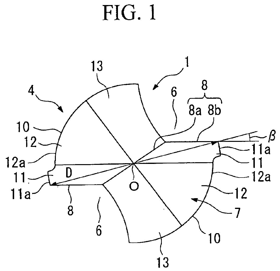
- Fig. 1 is an end view of a drill according to an embodiment of the present invention;
- Fig. 2 is a side view of a cutting portion of the drill according to the embodiment of the present invention;
- Fig. 3 is a cross sectional view of the drill according to the embodiment of the present invention, which is cut along a plane perpendicular to the central axis;
- Fig. 4 is a side view of the drill according to the embodiment of the present invention;
- Fig. 5 is a graph showing results of a first test in which examples of the present invention and comparative examples were compared.
- Fig. 6 is a schematic representation showing results of a second test in which examples of the present invention and comparative examples were compared.
- Figs. 7A and 7B are graphs showing results of a third test in which examples of the present invention and comparative examples were compared.
-
- An embodiment of the present invention will be described below with reference to Figs. 1 to 4, in which a drill 1 according to the present embodiment is shown. The drill 1 has a shape of a rod and is constructed of a cemented carbide as described below. A
main body 2 of the drill 1 includes ashank portion 3 and a cuttingportion 4. Twochip discharging grooves exterior surface 4a of the cuttingportion 4 in a rotationally symmetrical manner around a rotational axis O of themain body 2. - As shown in Figs. 1 and 2, cutting
edges inner surfaces chip discharging grooves end surface 7 of the cuttingportion 4. - As shown in Fig. 1, each of the
cutting edges central portion 8a and aperipheral portion 8b. Thecentral portion 8a has a shape of an approximately straight line and radially extends from the rotational axis O. Theperipheral portion 8b also has a shape of an approximately straight line, and extends to the periphery of the cuttingportion 4 in a manner such that thecentral portion 8a and theperipheral portion 8b form an obtuse angle. In Fig. 1, thecentral portion 8a and theperipheral portion 8b are smoothly connected, and the connecting part has a shape of an arc. The present invention, however, is not limited to this. Thecentral portion 8a and theperipheral portion 8b may also be angularly connected, forming an obtuse angle therebetween (for example, 150° to 170°). - The
end surface 7 of the cuttingportion 4 has a pair ofland portions land portions end surface 7, and approaches the other end of the drill 1 toward the periphery of theend surface 7. Each of theland portions cutting edges 8, which includes asecond flank face 11 and athird flank face 12. The second flank face is formed in the front region in the rotating direction, and has a positive and relatively small relief angle α1. Thethird flank face 12 is formed in the rear region of thesecond flank face 11 in the rotating direction, and has a relatively large relief angle α2 (> α1). In addition, a thinningsurface 13 is formed in the region still farther to the rear, and has a relief angle α3 which is larger than α2. - In the present embodiment, the flank faces in the
end surface 7 are formed by planes including thesecond flank face 11 and thethird flank face 12, as shown in Fig. 1. The present invention, however, is not limited to this. A conical flank face, or flank faces having other adequate shapes may also be adopted. - Each of the
inner surfaces chip discharging grooves peripheral portion 8b of the each of the cutting edges 8. In addition, astep surface 13a between thesecond flank face 11 in oneland portion 10 and the thinningsurface 13 in theother land portion 10 extends toward theshank portion 3 of the drill 1, forming a rake surface of thecentral portion 8a. - The second flank faces 11 and 11 are protruding in the radial direction relative to the periphery of the third flank faces 12 and 12, forming
margins margins chip discharging grooves exterior surface 4a of the cuttingportion 4. The maximum outside diameter (cutting edge diameter) D of the cuttingportion 4 represents the distance between the peripheral ends of thecutting edges margins - In Fig. 1 and Fig. 3, La is a distance along an arc around the
chips discharging groove 6, when the center of the arc is on the central axis. In addition, Lb is a distance along an arc at the periphery of theland portion 10. A groove width ratio La/Lb is in the range of 0.9 to 1.1. When the groove width ratio is smaller than 0.9, the width of thechip discharging grooves chip discharging grooves - As shown in Fig. 1 and Fig. 3, the
land portions chip discharging grooves land portions cutting edges main body 2 will be reduced. When the core diameter is larger than 0.42D, the depth of thechip discharging grooves chip discharging grooves cutting edges - The
chip discharging grooves shank portion 3 of the main body. Referring to Fig. 2, a helix angle of the chip discharging grooves relative to the rotational axis O is in the range of 5° to 15°, when the drill is seen from the side. When the helix angle is smaller than 5°, inclination of thechip discharging grooves inner surfaces 6a and 6a. which form the rake surfaces, will be too small. Thus, the sharpness of the cutting edges will be degraded. In addition, the helix angle will be too small relative to the direction in which the chips are generated by thecutting edges cutting edges - With reference to Fig. 2, a point angle γ between the lines extended from the
cutting edges end surface 7 of themain body 2 is in the range of 125° to 135°. When the point angle γ is smaller than 125°, vibration easily occurs during the hole forming process, especially in the case of cutting a hard steel. In addition, a time interval will be long in which thecutting edges - With reference to Fig. 1, a radial rake angle β is set to a negative value in a range of -5° to -10°, particularly at the
peripheral portion 8b of thecutting edge 8. When the value of the radial rake angle β is higher than -5°, fracture of thecutting edges - According to the present embodiment, at least the
cutting edges portion 4 of themain body 2 are constructed of the cemented carbide, which preferably comprises 10 ±2 wt% Co, 0.65 ±0.25 wt% Cr tungsten carbide (WC) for the balance, and inevitable impurities. The average particle diameter of the tungsten carbide (WC), which is the main component of the cemented carbide. is in the range of 0.1 to 1.0 µm. - With respect to conventional drills constructed of a cemented carbide, the composition of the cemented carbide was 9% Co, 8.1% TiC, 9.9% TaC, 1.1% NbC, and WC for the balance. In addition, the average particle diameter of WC, which is the main component of this cemented carbide, was in the range of approximately 2 to 3 µm. In such a case, the value of the radial rake angle must be lower than -25° to avoid fracture of the cutting edges. Accordingly, since the value of the radial rake angle was set to such a low value, the sharpness of the cutting edges was not sufficient.
- In contrast, according to the drill 1 of the present embodiment, the average particle diameter of WC is reduced, so that the radial rake angle may be set to a higher value, in the range of -5° to -10°. Accordingly, the sharpness of the cutting is improved. In addition, the versatility regarding the shape of the cutting edges is increased, and the resistance to fracture is maintained.
- As shown in Fig. 3, the surface of the cutting
portion 4 is coated with alayer 16, which is constructed of a hard material, for example a titanium compound. Accordingly, the resistances to fracture and to abrasion of thecutting edges - The performance of the drill 1, which has the above-described construction, is considered below in the case in which a hole is formed in a hard material of which the hardness after the heat treatment is higher than 40 HRC. The
main body 2 of the drill 1 is rotated around the rotational axis O, and is moved toward the work material in the direction of the rotational axis O. Since the point angle γ of the cuttingportion 4 is in the range of 125° to 135°, the drill 1 smoothly penetrates into the work material. In addition, the rigidity of the drill is sufficient relative to the hardness of the work material. Accordingly, fracture of thecutting edges cutting edges cutting edges cutting edges - In addition, since the core diameter is in the range of 0.38D to 0.42D, the rigidity of the
main body 2 is ensured and the space inside thechip discharging grooves - Since the work material is a hard die steel, chips generated by the
cutting edges chip discharging grooves main body 2 due to the clumping of the chips is prevented. In addition, the rigidity of the dill 1 is ensured, so that the fineness of the hole is maintained. - In accordance with the drill 1 of the present embodiment, the fineness of the hole is ensured even when a shallow hole, in which L/D is 3 or smaller as in the conventional case, is formed in a hard steel of which the hardness is higher than 40 HRC. More specifically, a hole is formed in which the circularity is excellent, and in which the amount of oversizing and surface roughness is small. In addition, fracture of the
cutting edges - Next, cutting tests in which samples according to the present invention is used will be described below.
- The samples used in the cutting tests had basically the same construction as the drill 1 described above in the embodiment. As shown in Table 1, samples of types A and B were prepared as examples of the present invention, and samples of types C, D, and E were prepared as comparative examples.
- With respect to the types A and B, the material of the samples was Z10 according to ISO, which is a cemented carbide comprising 10 ±2 wt% Co, 0.65 ±0.25 wt% Cr, WC for the balance, and inevitable impurities. The average particle diameter of WC was 1.0 µm. In addition, values of the core diameter, the groove width ratio, the ratio radial rake angle β of the
cutting edges - With respect to a work material, SKD11 according to the Japanese Industrial Standard (JIS). which is a cold die steel, was used after the heat treatment was performed. The hardness of the work material after the heat treatment was 60HRC.
Material (ISO) Core diameter Groove width ratio Radial rake angle Point Angle Helix angle Type A (Examples) Z10 0.40D 1.0:1 -7° 130° 10° Type B (Examples) Z10 0.38D 1.1:1 -7° 130° 10° Type C (Comparative Examples) M20 0.40D 1.0:1 -7° 130° 10° Type D (Comparative Examples) Z10 0.40D 1.0:1 -15° 120° 10° Type E (Comparative Examples) Z10 0.25D 1.0:1 -7° 130° 30° - In a first test, differences in tool lives according to the material were examined. In this test, samples of the types A, B, and C were used for forming holes which penetrate through the work material. The test was performed under the following conditions. That is, the cutting edge diameter D was 3 mm, the cutting speed was 10 m/min, the feed was 0.04 mm/rev, and the cutting depth was 9 mm (L/D = 3). In addition, a soluble emulsion (10% dilution) was used as a cutting lubricant.
- With respect to each of the types A, B and C, two samples were used in this test. The results of the test are shown in Fig. 5.
- Approximately 140 holes were formed by each sample of the type A, and 110 and 120 holes were formed by the samples of the type B. After the test, normal abrasion was observed in the
cutting portions 4 of the samples of the types A and B. In contrast, the samples of the type C were broken after approximately 30 holes were formed. Thus, the samples exhibited apparent differences in tool lives. - In a second test, differences in the fineness of the holes according to the radial rake angle and the point angle were examined.
- In this test, samples of the types A and D were used for forming holes which penetrate through the work material. The cutting edge diameter D was 10 mm, and the cutting depth was 30 mm (L/D = 3), In addition, the soluble emulsion (10% dilution) was used as the cutting lubricant.
- With respect to each of the types A and D, three samples were used in this test. The results of the test are shown in Fig. 6.
- First, holes were formed under conditions in which the feed was fixed to 0.10 mm/rev and the cutting speed was increased from 1 to 20 m/min, and amounts of oversizing in the formed holes were measured (see the upper section in the column "oversized" in Fig. 6). Next. holes were formed under conditions in which the cutting speed was fixed to 20 m/min and the feed was increased to 0.10 mm/rev, and amounts of oversizing in the formed holes were measured (see the lower section in the column "oversize" in Fig. 6).
- Degree of variation in amounts of oversizing in the holes formed by the samples of the type D was larger compared to the holes formed by the samples of the type A. In the case in which the feed was fixed, the sample of the type D broke when the cutting speed was 20 m/min, as is understood from the upper section in Fig. 6. In the case in which the cutting speed was fixed, the sample of the type D broke when the feed was 0.10 mm/rev. as is understood from the lower section in Fig. 6.
- First, holes were formed under conditions in which the feed was fixed to 0.10 mm/rev and the cutting speed was increased from 1 to 20 m/min, and surface roughnesses of the formed holes were measured (see the upper section in the column "surface roughness" in Fig. 6). Next, holes were formed under conditions in which the cutting speed was fixed to 20 m/min and the feed was increased to 0.10 mm/rev, and surface roughnesses of the formed holes were measured (see the lower section in the column "surface roughness" in Fig. 6).
- Degree of variation in the surface roughnesses of the holes formed by the samples of the types D was larger compared to the holes formed by the samples of the type A. In the case in which the feed was fixed, the sample of the type D broke when the cutting speed was 20 m/min, as is understood from the upper section in Fig. 6. In the case in which the cutting speed was fixed, the sample of the type D broke when the feed was 0.10 mm/rev, as is understood from the lower section in Fig. 6.
- First, holes were formed under conditions in which the feed was fixed to 0.10 mm/rev and the cutting speed was increased from 1 to 20 m/min, and circularities of the formed holes were measured (see the upper section in the column "circularity" in Fig. 6). Next, holes were formed under conditions in which the cutting speed was fixed to 20 m/min and the feed was increased to 0.10 mm/rev, and circularities of the formed holes were measured (see the lower section in the column "circularity" in Fig. 6).
- The circularities of the holes formed by the samples of the type D were larger compared to the holes formed by the samples of the type A. In the case in which the feed was fixed, the sample of the type D broke when the cutting speed was 20 m/min, as is understood from the upper section in Fig. 6. In the case in which the cutting speed was fixed, the sample of the type D broke when the feed was 0.10 mm/rev, as is understood from the lower section in Fig. 6.
- In a third test, variation of amounts of abrasion in the flank face and variation of amounts of oversizing were examined.
- In this test, samples of the types A and E were used for forming holes which penetrate through the work material. With respect to the work material, SKD61 according to the Japanese Industrial Standard (JIS) was used as the work material. The hardness of the work material after the heat treatment was 50 HRC. The outside diameter D was 10 mm, the cutting speed was 30 m/min. the feed was 0.10 mm/rev, and the cutting depth was 30 mm (L/D = 3). In addition, the soluble emulsion (10% dilution) was used as the cutting lubricant.
- As is understood from Fig. 7A, the amount of abrasion in the sample of the type A after forming 100 holes (approximately 0.39 mm) and the amount of abrasion in the sample of the type E after forming 22 holes were approximately the same. At this time, normal abrasion was observed in the samples of both types, and the samples were not broken. The tool life of the sample of the type A was 3.5 times longer than that of the type E.
- As shown in Fig 7B, the amounts of oversizing caused in the holes formed by the sample of the type A were significantly less compared to the holes formed by the sample of the type E. Although the sample of the type E broke after forming approximately 30 holes, the sample of the type A could form more than 100 holes.
- From the results of the above-described first to third tests, it is understood that the fineness of the holes is improved and the tool life is increased by using the samples of the types A and B, which were prepared as examples of the present invention. In addition, it was proved that the material, the radial rake angle, the point angle, the core diameter, and the helix angle greatly affect the fineness of the holes and the tool life.
- Although the drill 1 according to the embodiment of the present invention was a unitary type, the present invention is not limited to this. A drill of a brazed type, throwaway type, etc., may also be used as long as the
cutting edges - In addition, the work material is not limited to hard steels. The present invention may also be applied in the process of forming a hole in a steel of which the hardness is 40 HRC or less.
- In addition, the present invention is not limited to drills, and may be applied in various hole forming tools.
Claims (11)
- A hole forming tool (1) which rotates arouund a rotational axis (0), comprising:wherein a radial rake angle (β) of said cutting edges (8) is set to a negative value in the range of -5° to -10°,one or more chip discharging grooves (6) which are helically formed around the rotational axis (0) in the exterior surface (4a) of said hole forming tool (1); andone or more cutting edges (8) which are formed along ridge lines between inner surfaces (6a) of said chip discharging grooves (6), which are facing the rotating direction, and flank faces (11) formed at an end of said hole forming tool (1),
wherein a point angle(γ) is in the range of 125°to 135°, and
wherein a groove width radio is in the range of 0.9 to 1.1. - A hole forming tool (1) which rotates around a rotational axis (0), comprising:wherein a radial rake angle (β) of said one or more chip discharging cutting edges (8) is set to a negative value in the range of -5° to -10°, wherein a point angle (γ) is in the range of 125° to 135°, and wherein a core diameter is in the range of 0.38D to 0.42D, in which D is a cutting edge diameter of said hole forming tool (1).one or more chip discharging grooves (6) which are helically formed around the rotational axis (0) in the exterior surface (4a) of said hole forming tool (1); andone or more cutting edges (8) which are formed along ridge lines between inner surfaces (6a) of said chip discharging grooves (6), which are facing the rotating direction, and flank faces (11) formed at an end of said hole forming tool (1),
- A hole forming tool (1) according to claim 1 or 2,
wherein a helix angle () of said chip discharging gooves (6) is in the range of 5° to 15°. - A hole forming tool (1) which rotates around a rotational axis (0), comprising:wherein a radial rake angle (β) of said one or more chip discharging cutting edges (8) is set to a negative value in the range of -5° to -10°, wherein a point angle (γ) is in the range of 125° to 135°, and wherein a helix angle () of said chip discharging grooves (6) is in the range of 5° to 15°.one or more chip discharging grooves (6) which are helically formed around the rotational axis (0) in the exterior surface (4a) of said hole forming tool (1); andone or more cutting edges (8) which are formed along ridge lines between inner surfaces (6a) of said chip discharging grooves (6) which are facing the rotating direction, and flank faces (11) formed at an end of said hole forming tool (1),
- A hole forming tool (1) which rotates around a rotational axis (0) comprising:wherein a radial rake angle (β) of said one or more chip discharging cutting edges (8) is set to a negative value in the range of -5° to -10°, wherein a point angle (γ) is in the range of 125° to 135°, and wherein at least parts including said cutting edges (8) are constructed of a cemented carbide and an average particle diameter of WC, which is comprised in said cemented carbide, is in the range of 0.1 to 1.0 µm.one or more chip discharging grooves (6) which are helically formed around the rotational axis (0) in the exterior surface (4a) of said hole forming tool (1); andone or more cutting edges (8) which are formed along ridge lines between inner surfaces (6a) of said chip discharging grooves (6), which are facing the rotating direction, and flank faces (11) formed at an end of said hole forming tool (1),
- A hole forming tool (1) which rotates around a rotational axis (0), comprising:wherein a radial rake angle (β) of said one or more chip discharging cutting edges (8) is set to a negative value in the range of -5° to -10°, wherein a point angel (γ) is in the range of 125° to 135°, and wherein at least a part including said chip discharging grooves (6) of said hole forming tool (1) is coated with a layer (16) constructed of a hard material.one or more chip discharging grooves (6) which are helically formed around the rotational axis (0) in the exterior surface (4a) of said hole forming tool (1); andone or more cutting edges (8) which are formed along ridge lines between inner surfaces (6a) of said chip discharging grooves (6), which are facing the rotating direction, and flank faces (11) formed at an end of said hole forming tool (1),
- A hole forming tool (1) according to claim 5 or 6,
wherein a groov width ratio is in the range of 0.9 to 1.1. - A hole forming tool (1) according to claim 1, 5 or 6,
wherein, a core diameter is in the range of 0.38D to 0.42D, in which D is a cutting edge diameter of said hole forming tool (1). - A hole forming tool (1) according to claim 1, 2, 5 or 6,
wherein a helix angle () of said chip discharging grooves (6) is in the range of 5° to 15°. - A hole forming tool (1) according to any one of the preceding claims, wherein the main body (2) of said hole forming tool (1) is constructed of a cemented carbide which comprises 10 ±2 wt% Co, 0.65 ±0.25 wt% Cr,WC for the balance, and inevitable impurities.
- A hole forming tool (1) which rotates around a rotational axis (0), comprising:wherein a radial rake angle (β) of said one or more chip discharging cutting edges (8) is set to a negative value in the range of -5° to -10°, wherein a point angle (γ) is in the range of 125° to 135°, and wherein the main body (2) of said hole forming tool (1) is constructed of a cemented carbide which comprises 10 ±2 wt% Co,0.65 ±0.25 wt% Cr, WC for the balance, and inevitable impurities.one or more chip discharging grooves (6) which are helically formed around the rotational axis (0) in the exterior surface (4a) of said hole forming tool (1), andone or more cutting edges (8) which are formed along ridge lines between inner surfaces (6a) of said chip discharging grooves (6), which are facing the rotating direction, and flank faces (11) formed at an end of said hole forming tool (1),
Applications Claiming Priority (4)
| Application Number | Priority Date | Filing Date | Title |
|---|---|---|---|
| JP2000264591 | 2000-08-31 | ||
| JP2000264591 | 2000-08-31 | ||
| JP2001088501 | 2001-03-26 | ||
| JP2001088501A JP2002144125A (en) | 2000-08-31 | 2001-03-26 | Drilling tool |
Publications (3)
| Publication Number | Publication Date |
|---|---|
| EP1184114A2 true EP1184114A2 (en) | 2002-03-06 |
| EP1184114A3 EP1184114A3 (en) | 2002-05-29 |
| EP1184114B1 EP1184114B1 (en) | 2004-11-03 |
Family
ID=26599033
Family Applications (1)
| Application Number | Title | Priority Date | Filing Date |
|---|---|---|---|
| EP01107731A Expired - Lifetime EP1184114B1 (en) | 2000-08-31 | 2001-03-30 | Hole forming tool |
Country Status (5)
| Country | Link |
|---|---|
| US (1) | US20020044843A1 (en) |
| EP (1) | EP1184114B1 (en) |
| JP (1) | JP2002144125A (en) |
| KR (1) | KR20020017908A (en) |
| DE (1) | DE60106829T2 (en) |
Cited By (6)
| Publication number | Priority date | Publication date | Assignee | Title |
|---|---|---|---|---|
| GB2417447A (en) * | 2004-08-23 | 2006-03-01 | Osg Corp | A twist drill bit |
| US7201543B2 (en) * | 2000-06-02 | 2007-04-10 | Kennametal Inc. | Twist drill and method for producing a twist drill which method includes forming a flute of a twist drill |
| GB2491956B (en) * | 2011-06-13 | 2015-08-12 | Element Six Ltd | Twist drill tips, precursor constructions for use in making same, and methods for making and using same |
| US9199315B2 (en) | 2000-06-02 | 2015-12-01 | Kennametal Inc. | Twist drill and method for producing a twist drill which method includes forming a flute of a twist drill |
| EP2260965A3 (en) * | 2005-03-24 | 2018-07-25 | EMUGE-Werk Richard Glimpel GmbH & Co.KG Fabrik für Präzisionswerkzeuge | Drilling thread milling cutter |
| EP3263256B1 (en) | 2015-02-23 | 2019-07-31 | Sumitomo Electric Industries, Ltd. | Rotating tool |
Families Citing this family (18)
| Publication number | Priority date | Publication date | Assignee | Title |
|---|---|---|---|---|
| EP1273374A1 (en) * | 2001-07-05 | 2003-01-08 | Mitsubishi Materials Corporation | Throw-away tip for use in drilling work and throw-away drilling tool |
| EP1923157B1 (en) * | 2001-07-10 | 2020-07-29 | Mitsubishi Materials Corporation | Drill |
| US20030185640A1 (en) * | 2002-03-27 | 2003-10-02 | Eiji Ito | Multiple rake drill bits |
| SE525336C2 (en) * | 2002-05-17 | 2005-02-01 | Sandvik Ab | Drilling tools for hole drilling in metallic materials |
| US7306411B2 (en) * | 2002-09-03 | 2007-12-11 | Mitsubishi Materials Corporation | Drill with groove width variation along the drill and double margin with a thinning section at the tip |
| JP3834544B2 (en) * | 2002-11-29 | 2006-10-18 | オーエスジー株式会社 | Tap and manufacturing method thereof |
| DE102004058163A1 (en) * | 2004-12-02 | 2006-06-08 | Kennametal Inc. | Drilling / chamfering tool |
| JP2006231430A (en) * | 2005-02-22 | 2006-09-07 | Tungaloy Corp | Centering drill and machining method using the same |
| US20090191016A1 (en) * | 2005-04-04 | 2009-07-30 | Osg Corporation | Drill |
| CN100368115C (en) * | 2005-04-10 | 2008-02-13 | 江苏飞达工具股份有限公司 | A method of improving the service life of rolling twist drill |
| GB2428611B (en) * | 2005-08-02 | 2007-10-03 | Dormer Tools | Twist drill |
| KR100649431B1 (en) * | 2006-01-23 | 2006-11-28 | 남궁규성 | Drill with fluid guiding means |
| JP4725369B2 (en) * | 2006-03-03 | 2011-07-13 | 三菱マテリアル株式会社 | Drill |
| US8261345B2 (en) | 2006-10-23 | 2012-09-04 | Endeavors Technologies, Inc. | Rule-based application access management |
| JP5077996B2 (en) * | 2006-12-14 | 2012-11-21 | 株式会社不二越 | Carbide twist drill |
| US8892738B2 (en) | 2007-11-07 | 2014-11-18 | Numecent Holdings, Inc. | Deriving component statistics for a stream enabled application |
| DE102014204700B4 (en) | 2014-03-13 | 2022-02-17 | Kennametal Inc. | Rotary tool, in particular drilling tool and method for producing a rotary tool |
| DE102019202165B4 (en) * | 2019-02-19 | 2022-10-27 | Kennametal Inc. | Drill and method of machining a workpiece |
Citations (3)
| Publication number | Priority date | Publication date | Assignee | Title |
|---|---|---|---|---|
| JPH11244120A (en) | 1998-03-03 | 1999-09-14 | Nippon Crescent Kk | Method, device and containers for serving roasted and steamed foods on rotary eating table |
| JP2000004058A (en) | 1983-11-25 | 2000-01-07 | Univ Leland Stanford Jr | Fiber optical amplifier system and optical signal amplification method |
| JP2000093834A (en) | 1998-09-24 | 2000-04-04 | Toyobo Co Ltd | Magnetic stand |
Family Cites Families (9)
| Publication number | Priority date | Publication date | Assignee | Title |
|---|---|---|---|---|
| US2731711A (en) * | 1954-05-13 | 1956-01-24 | Gen Electric | Sintered tungsten carbide composition |
| JPS5943247B2 (en) * | 1979-06-25 | 1984-10-20 | 三菱マテリアル株式会社 | Surface-coated cemented carbide miniature drill |
| JPS57211406A (en) * | 1981-06-17 | 1982-12-25 | Toshiaki Hosoi | Drill |
| US4556347A (en) * | 1984-05-11 | 1985-12-03 | Lockheed Corporation | Split-point twist drill |
| ES2029456T3 (en) * | 1986-06-07 | 1992-08-16 | Hertel Aktiengesellschaft Werkzeuge + Hartstoffe | PROCEDURE FOR SHARPENING A SPIRAL DRILL. |
| US5230593A (en) * | 1987-12-14 | 1993-07-27 | Mitsubishi Kinzoku Kabushiki Kaisha | Twist drill |
| JP3461538B2 (en) * | 1993-09-14 | 2003-10-27 | 三菱マテリアル神戸ツールズ株式会社 | Super hard drill |
| US5709587A (en) * | 1996-03-25 | 1998-01-20 | Kennametal Inc. | Method and apparatus for honing an elongate rotary tool |
| SE518885C2 (en) * | 1998-02-20 | 2002-12-03 | Seco Tools Ab | Ways to make inserts in submicron cemented carbide |
-
2001
- 2001-03-26 JP JP2001088501A patent/JP2002144125A/en active Pending
- 2001-03-30 EP EP01107731A patent/EP1184114B1/en not_active Expired - Lifetime
- 2001-03-30 US US09/821,069 patent/US20020044843A1/en not_active Abandoned
- 2001-03-30 KR KR1020010017012A patent/KR20020017908A/en not_active Ceased
- 2001-03-30 DE DE60106829T patent/DE60106829T2/en not_active Expired - Lifetime
Patent Citations (3)
| Publication number | Priority date | Publication date | Assignee | Title |
|---|---|---|---|---|
| JP2000004058A (en) | 1983-11-25 | 2000-01-07 | Univ Leland Stanford Jr | Fiber optical amplifier system and optical signal amplification method |
| JPH11244120A (en) | 1998-03-03 | 1999-09-14 | Nippon Crescent Kk | Method, device and containers for serving roasted and steamed foods on rotary eating table |
| JP2000093834A (en) | 1998-09-24 | 2000-04-04 | Toyobo Co Ltd | Magnetic stand |
Cited By (7)
| Publication number | Priority date | Publication date | Assignee | Title |
|---|---|---|---|---|
| US7201543B2 (en) * | 2000-06-02 | 2007-04-10 | Kennametal Inc. | Twist drill and method for producing a twist drill which method includes forming a flute of a twist drill |
| US9199315B2 (en) | 2000-06-02 | 2015-12-01 | Kennametal Inc. | Twist drill and method for producing a twist drill which method includes forming a flute of a twist drill |
| GB2417447A (en) * | 2004-08-23 | 2006-03-01 | Osg Corp | A twist drill bit |
| EP2260965A3 (en) * | 2005-03-24 | 2018-07-25 | EMUGE-Werk Richard Glimpel GmbH & Co.KG Fabrik für Präzisionswerkzeuge | Drilling thread milling cutter |
| GB2491956B (en) * | 2011-06-13 | 2015-08-12 | Element Six Ltd | Twist drill tips, precursor constructions for use in making same, and methods for making and using same |
| EP3263256B1 (en) | 2015-02-23 | 2019-07-31 | Sumitomo Electric Industries, Ltd. | Rotating tool |
| EP3263256B2 (en) † | 2015-02-23 | 2024-09-04 | Sumitomo Electric Industries, Ltd. | Rotating tool |
Also Published As
| Publication number | Publication date |
|---|---|
| US20020044843A1 (en) | 2002-04-18 |
| EP1184114B1 (en) | 2004-11-03 |
| JP2002144125A (en) | 2002-05-21 |
| KR20020017908A (en) | 2002-03-07 |
| EP1184114A3 (en) | 2002-05-29 |
| DE60106829D1 (en) | 2004-12-09 |
| DE60106829T2 (en) | 2005-10-27 |
Similar Documents
| Publication | Publication Date | Title |
|---|---|---|
| EP1184114B1 (en) | Hole forming tool | |
| US7909545B2 (en) | Ballnose end mill | |
| US7033643B2 (en) | Process of manufacturing a coated body | |
| EP3444059B1 (en) | Small-diameter drill bit | |
| US20030185640A1 (en) | Multiple rake drill bits | |
| US5322394A (en) | Highly stiff end mill | |
| US20100028098A1 (en) | Drill bit configuration | |
| US20130315681A1 (en) | Rotary cutter | |
| WO2019131177A1 (en) | Drill | |
| EP1741507B1 (en) | Twist drill | |
| WO2014057783A1 (en) | Ball end mill and insert | |
| GB2417447A (en) | A twist drill bit | |
| JP6086180B1 (en) | Replaceable blade cutting tool and insert | |
| US20230173594A1 (en) | Drill and method for manufacturing machined product | |
| JP4975395B2 (en) | Ball end mill | |
| JPH0780714A (en) | Ultra-hard drill | |
| WO2007039949A1 (en) | Boring tool and method of boring pilot hole | |
| JP3337804B2 (en) | End mill | |
| JP4996278B2 (en) | Long drill made of super hard material for deep hole machining | |
| JP4053295B2 (en) | Drilling tool | |
| JPH0569214A (en) | Drilling tool | |
| JPH0532164B2 (en) | ||
| JP2002172506A (en) | Covered twist drill | |
| JPH09103918A (en) | Boring tool | |
| KR200211512Y1 (en) | Reamer for complex machining |
Legal Events
| Date | Code | Title | Description |
|---|---|---|---|
| PUAI | Public reference made under article 153(3) epc to a published international application that has entered the european phase |
Free format text: ORIGINAL CODE: 0009012 |
|
| AK | Designated contracting states |
Kind code of ref document: A2 Designated state(s): AT BE CH CY DE DK ES FI FR GB GR IE IT LI LU MC NL PT SE TR |
|
| AX | Request for extension of the european patent |
Free format text: AL;LT;LV;MK;RO;SI |
|
| PUAL | Search report despatched |
Free format text: ORIGINAL CODE: 0009013 |
|
| AK | Designated contracting states |
Kind code of ref document: A3 Designated state(s): AT BE CH CY DE DK ES FI FR GB GR IE IT LI LU MC NL PT SE TR |
|
| AX | Request for extension of the european patent |
Free format text: AL;LT;LV;MK;RO;SI |
|
| RIC1 | Information provided on ipc code assigned before grant |
Free format text: 7B 23B 51/02 A, 7C 22C 29/02 B |
|
| 17P | Request for examination filed |
Effective date: 20020916 |
|
| 17Q | First examination report despatched |
Effective date: 20021227 |
|
| AKX | Designation fees paid |
Designated state(s): DE FR GB IT |
|
| GRAP | Despatch of communication of intention to grant a patent |
Free format text: ORIGINAL CODE: EPIDOSNIGR1 |
|
| GRAS | Grant fee paid |
Free format text: ORIGINAL CODE: EPIDOSNIGR3 |
|
| GRAA | (expected) grant |
Free format text: ORIGINAL CODE: 0009210 |
|
| AK | Designated contracting states |
Kind code of ref document: B1 Designated state(s): DE FR GB IT |
|
| REG | Reference to a national code |
Ref country code: GB Ref legal event code: FG4D |
|
| REF | Corresponds to: |
Ref document number: 60106829 Country of ref document: DE Date of ref document: 20041209 Kind code of ref document: P |
|
| REG | Reference to a national code |
Ref country code: IE Ref legal event code: FG4D |
|
| ET | Fr: translation filed | ||
| PLBE | No opposition filed within time limit |
Free format text: ORIGINAL CODE: 0009261 |
|
| STAA | Information on the status of an ep patent application or granted ep patent |
Free format text: STATUS: NO OPPOSITION FILED WITHIN TIME LIMIT |
|
| 26N | No opposition filed |
Effective date: 20050804 |
|
| REG | Reference to a national code |
Ref country code: FR Ref legal event code: PLFP Year of fee payment: 16 |
|
| REG | Reference to a national code |
Ref country code: FR Ref legal event code: PLFP Year of fee payment: 17 |
|
| REG | Reference to a national code |
Ref country code: FR Ref legal event code: PLFP Year of fee payment: 18 |
|
| PGFP | Annual fee paid to national office [announced via postgrant information from national office to epo] |
Ref country code: DE Payment date: 20200320 Year of fee payment: 20 Ref country code: GB Payment date: 20200323 Year of fee payment: 20 |
|
| PGFP | Annual fee paid to national office [announced via postgrant information from national office to epo] |
Ref country code: FR Payment date: 20200319 Year of fee payment: 20 |
|
| PGFP | Annual fee paid to national office [announced via postgrant information from national office to epo] |
Ref country code: IT Payment date: 20200318 Year of fee payment: 20 |
|
| REG | Reference to a national code |
Ref country code: DE Ref legal event code: R071 Ref document number: 60106829 Country of ref document: DE |
|
| REG | Reference to a national code |
Ref country code: GB Ref legal event code: PE20 Expiry date: 20210329 |
|
| PG25 | Lapsed in a contracting state [announced via postgrant information from national office to epo] |
Ref country code: GB Free format text: LAPSE BECAUSE OF EXPIRATION OF PROTECTION Effective date: 20210329 |