EP1182334A2 - Kühleranordnung - Google Patents
Kühleranordnung Download PDFInfo
- Publication number
- EP1182334A2 EP1182334A2 EP01115149A EP01115149A EP1182334A2 EP 1182334 A2 EP1182334 A2 EP 1182334A2 EP 01115149 A EP01115149 A EP 01115149A EP 01115149 A EP01115149 A EP 01115149A EP 1182334 A2 EP1182334 A2 EP 1182334A2
- Authority
- EP
- European Patent Office
- Prior art keywords
- inlet
- outlet
- cooler
- coolers
- lines
- Prior art date
- Legal status (The legal status is an assumption and is not a legal conclusion. Google has not performed a legal analysis and makes no representation as to the accuracy of the status listed.)
- Granted
Links
Images




Classifications
-
- F—MECHANICAL ENGINEERING; LIGHTING; HEATING; WEAPONS; BLASTING
- F28—HEAT EXCHANGE IN GENERAL
- F28D—HEAT-EXCHANGE APPARATUS, NOT PROVIDED FOR IN ANOTHER SUBCLASS, IN WHICH THE HEAT-EXCHANGE MEDIA DO NOT COME INTO DIRECT CONTACT
- F28D1/00—Heat-exchange apparatus having stationary conduit assemblies for one heat-exchange medium only, the media being in contact with different sides of the conduit wall, in which the other heat-exchange medium is a large body of fluid, e.g. domestic or motor car radiators
- F28D1/02—Heat-exchange apparatus having stationary conduit assemblies for one heat-exchange medium only, the media being in contact with different sides of the conduit wall, in which the other heat-exchange medium is a large body of fluid, e.g. domestic or motor car radiators with heat-exchange conduits immersed in the body of fluid
- F28D1/04—Heat-exchange apparatus having stationary conduit assemblies for one heat-exchange medium only, the media being in contact with different sides of the conduit wall, in which the other heat-exchange medium is a large body of fluid, e.g. domestic or motor car radiators with heat-exchange conduits immersed in the body of fluid with tubular conduits
- F28D1/0408—Multi-circuit heat exchangers, e.g. integrating different heat exchange sections in the same unit or heat exchangers for more than two fluids
- F28D1/0426—Multi-circuit heat exchangers, e.g. integrating different heat exchange sections in the same unit or heat exchangers for more than two fluids with units having particular arrangement relative to the large body of fluid, e.g. with interleaved units or with adjacent heat exchange units in common air flow or with units extending at an angle to each other or with units arranged around a central element
-
- F—MECHANICAL ENGINEERING; LIGHTING; HEATING; WEAPONS; BLASTING
- F01—MACHINES OR ENGINES IN GENERAL; ENGINE PLANTS IN GENERAL; STEAM ENGINES
- F01P—COOLING OF MACHINES OR ENGINES IN GENERAL; COOLING OF INTERNAL-COMBUSTION ENGINES
- F01P11/00—Component parts, details, or accessories not provided for in, or of interest apart from, groups F01P1/00 - F01P9/00
- F01P11/04—Arrangements of liquid pipes or hoses
-
- F—MECHANICAL ENGINEERING; LIGHTING; HEATING; WEAPONS; BLASTING
- F01—MACHINES OR ENGINES IN GENERAL; ENGINE PLANTS IN GENERAL; STEAM ENGINES
- F01P—COOLING OF MACHINES OR ENGINES IN GENERAL; COOLING OF INTERNAL-COMBUSTION ENGINES
- F01P3/00—Liquid cooling
- F01P3/18—Arrangements or mounting of liquid-to-air heat-exchangers
-
- F—MECHANICAL ENGINEERING; LIGHTING; HEATING; WEAPONS; BLASTING
- F28—HEAT EXCHANGE IN GENERAL
- F28F—DETAILS OF HEAT-EXCHANGE AND HEAT-TRANSFER APPARATUS, OF GENERAL APPLICATION
- F28F9/00—Casings; Header boxes; Auxiliary supports for elements; Auxiliary members within casings
- F28F9/02—Header boxes; End plates
- F28F9/0246—Arrangements for connecting header boxes with flow lines
-
- F—MECHANICAL ENGINEERING; LIGHTING; HEATING; WEAPONS; BLASTING
- F01—MACHINES OR ENGINES IN GENERAL; ENGINE PLANTS IN GENERAL; STEAM ENGINES
- F01P—COOLING OF MACHINES OR ENGINES IN GENERAL; COOLING OF INTERNAL-COMBUSTION ENGINES
- F01P3/00—Liquid cooling
- F01P3/18—Arrangements or mounting of liquid-to-air heat-exchangers
- F01P2003/182—Arrangements or mounting of liquid-to-air heat-exchangers with multiple heat-exchangers
-
- F—MECHANICAL ENGINEERING; LIGHTING; HEATING; WEAPONS; BLASTING
- F28—HEAT EXCHANGE IN GENERAL
- F28D—HEAT-EXCHANGE APPARATUS, NOT PROVIDED FOR IN ANOTHER SUBCLASS, IN WHICH THE HEAT-EXCHANGE MEDIA DO NOT COME INTO DIRECT CONTACT
- F28D21/00—Heat-exchange apparatus not covered by any of the groups F28D1/00 - F28D20/00
- F28D2021/0019—Other heat exchangers for particular applications; Heat exchange systems not otherwise provided for
- F28D2021/008—Other heat exchangers for particular applications; Heat exchange systems not otherwise provided for for vehicles
- F28D2021/0082—Charged air coolers
-
- F—MECHANICAL ENGINEERING; LIGHTING; HEATING; WEAPONS; BLASTING
- F28—HEAT EXCHANGE IN GENERAL
- F28D—HEAT-EXCHANGE APPARATUS, NOT PROVIDED FOR IN ANOTHER SUBCLASS, IN WHICH THE HEAT-EXCHANGE MEDIA DO NOT COME INTO DIRECT CONTACT
- F28D21/00—Heat-exchange apparatus not covered by any of the groups F28D1/00 - F28D20/00
- F28D2021/0019—Other heat exchangers for particular applications; Heat exchange systems not otherwise provided for
- F28D2021/008—Other heat exchangers for particular applications; Heat exchange systems not otherwise provided for for vehicles
- F28D2021/0091—Radiators
- F28D2021/0094—Radiators for recooling the engine coolant
Definitions
- the invention relates to a cooler arrangement, each consisting of two header boxes having coolers, for cooling various fluids, whose in at least one Row of flat tubes connecting the header boxes across the fan axis of the radial fan arranged inside the cooler arrangement run with a front wall and a rear wall as well as with inlet and outlet and with inlet and outlet Drain lines for fluid flowing through at least two coolers Collection boxes are connected.
- the cooler arrangement is based on the previously unpublished patent application DE 199 50 753.8 by the applicant.
- the inflow and outflow lines are relatively flat there and therefore save space educated. They connect the two side and the bottom in Fig. 1 there arranged coolers, which are coolant coolers there. Entry and exit the inflow or outflow lines in or out of the collection box are carried out there via the End faces of the collection box. The inlet and outlet of the coolant are on the back wall. With such training, not everyone can Operating and connection conditions are met.
- the object of the invention is to design the cooler arrangement so that it is suitable for other conditions of use or connection, the compact and space-saving design should be retained and an efficient one Heat exchange in the coolers connected to the inlet and outlet pipes can take place.
- the solution according to the invention is that the one inlet or outlet at the Rear, preferably in a corner area of the rear wall, and the other zu-or Drain on the front, preferably in the diagonal corner area of the Front wall, is arranged, the length and the cross section of the inlet and outlet Drain lines for each connected cooler is approximately the same and the inlet and outlet Drain lines are modularly pluggable.
- the arrangement of the inlets and outlets according to the invention ensures a even distribution of the amount of coolant to the cooler without To have to arrange regulatory elements in the lines.
- the length of the Zu and Drain lines to and from the coolers are at least approximately the same size. Consequently the flow resistances are about the same, which means that all connected cooler in about the same amount of coolant and in all connected coolers equal temperature differences between the Cooling air and the coolant are present, creating an efficient heat exchange is reached.
- the cooler arrangement according to the invention is for different types of connection Suitable, the one inlet or outlet on the front wall and the other inlet or Require drain on the rear wall. Because of the modular The inlet and outlet lines can be plugged together differently Circuit variants implemented economically using many identical parts become.
- the inflow or outflow lines have a flat, preferably rectangular, Cross section on, whereby the cooler arrangement remains compact. They consist of Elbows, sleeves, T - pieces and cross pieces made of plastic injection molding and from straight and / or curved line sections, preferably from Aluminum, for example manufactured as an extruded profile.
- the inlet or outlet on the rear wall has two long inlet or outlet lines for the entry or exit of two coolers and a short inlet or outlet line for the third cooler and the inlet or outlet on the front wall has a long inlet or Drain line and two short inlet or outlet lines, the length of the inlet -or drain lines for all three coolers is approximately the same.
- claim 5 stipulates for two coolers that the inlet or outlet Drain on the rear wall has a long and a short inlet or outlet pipe and the inlet or outlet on the front wall as well, the length of the inlet or outlet Drain lines of two coolers is approximately the same.
- the cooler arrangement is box-shaped and is intended for motor vehicles. 1 and 2, the upper cooler 1, a charge air cooler and the two side coolers 2 and 4 and the lower cooler 3 of the cooler arrangement can be seen, as well as a radial fan 7 enclosed by the cooler arrangement with a fan axis V.
- the cooler arrangement has a front wall F and a rear wall R.
- the flat tubes 8 of all coolers 1, 2, 3, 4 run transversely to the fan axis V. They were only partially drawn in in FIG. 1 in the side cooler 2 .
- the coolers 2, 3 and 4 are coolant coolers which are connected by means of the inlet and outlet lines L.
- arrows 6 have been drawn in, which indicate the direction of flow through the lines L and the coolers 2, 3 in the flat tubes 8 .
- the flat tubes 8 thus run in the direction of the arrows 6 shown in the figures in the coolers 2, 3 and 4 and thus transversely to the Vertilatorachse V shown in FIG. 1.
- the inlet Z of the cooling liquid is arranged in the corner region E on the rear wall R.
- the drain A is located in the diagonal corner area E on the front wall F.
- the coolers 1, 2, 3 and 4 each have two collecting tanks 5, whereby two collecting boxes 5 of adjacent coolers 1 and 2, 2 and 3 as well as 4 and 1 form an edge of the cooler arrangement where they lie closely together in order to close off the cooler arrangement and thereby force the cooling air sucked in by the radial fan 10 (FIG. 7) between the flat tubes 8 the cooler to flow through.
- 1 to 6 show the collecting boxes 5 lying one against the other.
- the inlet or outlet lines L have an approximately rectangular cross section. Their length is about the same - related to each individual cooler. In FIG. 1, the vertical inlet or outlet line L leads to the cooler 3 and the horizontal one to the cooler 5. The lengths of the inlet or outlet lines L of these two coolers 3 and 5 are approximately the same. From Fig. 2 it can be seen that the longer curved line 12 is assigned to the cooler 2 , so that overall there are approximately the same line lengths for each cooler 2, 3, 4 .
- the inflow or outflow lines L consist of straight line sections 11, of curved line sections 12, of elbows 13 and cross pieces 14 which are connected by means of connecting sleeves 15 . They can be plugged together using seals 16 .
- the straight and curved line sections 11; 12 consist of extruded aluminum profiles.
- the manifold 13 and the cross pieces 14 are molded plastic parts. With such a design, any circuit variants, ie fluidic connections of several coolers, can be implemented inexpensively.
- the side cooler 2 and the lower cooler 3 are connected by means of the inlet and outlet lines L. These are also provided as coolant coolers.
- the other side cooler 4 can, for. B. serve the oil cooling.
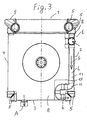
- the vertical line L in FIG. 3 leads to the lower cooler 3.
- a cross piece 14 (FIG. 7) is arranged at the inlet Z so that the cooling liquid can also reach the side cooler 2 via a short line attachment.
- Fig. 4 shows that the longer, curved line 12 leads from the side cooler 2 to the outlet A.
- the lengths of the inlet or outlet lines L assigned to each cooler 2 and 3 are approximately the same.
- One inlet or outlet Z, A can be found in a corner area E of the rear wall R and the other inlet or outlet Z, A can be found in the diagonal corner area E of the front wall F.
- These features common to all variants also have the exemplary embodiment from FIGS. 5 and 6 in which the two side coolers 2 and 4 are connected to one another.
- the rear wall R has not been drawn in FIG. 5 and the front wall F has also been omitted in FIG. 6. This makes the radial fan 7, which is located inside the cooler arrangement, visible.
- FIG. 7 shows a T-piece 14 which can be produced as an injection molded part and FIG. 8 shows an inlet or outlet line L.
- the cross piece has a round inlet or outlet connection and three flat branches which are connected by means of the sleeves 16 (FIG. 8). can be plugged together with the elbows 13 or the straight 11 or curved line sections 12 as required. Seals 16 are used for this.
Landscapes
- Engineering & Computer Science (AREA)
- Mechanical Engineering (AREA)
- General Engineering & Computer Science (AREA)
- Chemical & Material Sciences (AREA)
- Combustion & Propulsion (AREA)
- Physics & Mathematics (AREA)
- Thermal Sciences (AREA)
- Heat-Exchange Devices With Radiators And Conduit Assemblies (AREA)
Abstract
Description
- Fig. 1
- eine perspektivische Ansicht auf die Kühleranordnung schräg von hinten;
- Fig. 2
- eine Ansicht auf die Frontwand der Kühleranordnung aus Fig. 1;
- Fig. 3
- eine Ansicht auf die Rückwand eines zweiten Ausführungsbeispiels;
- Fig.4
- die zu Fig. 3 gehörende Ansicht auf die Frontwand;
- Fig.5
- perspektivische Ansicht, schräg von hinten, einer dritten Ausführung;
- Fig. 6
- die Ansicht der dritten Ausführung von vorne gesehen;
- Fig. 7
- ein T - Stück;
- Fig. 8
- zusammensteckbare Zu - oder Ablaufleitung;
Claims (5)
- Kühleranordnung bestehend aus je zwei Sammelkästen (5) aufweisenden, Kühlern (1, 2, 3, 4), zur Kühlung verschiedener Fluide, deren in mindestens einer Reihe angeordnete, die Sammelkästen (5) verbindende Flachrohre quer zur Ventilatorachse (V) des im Inneren der Kühleranordnung angeordneten Radialventilators (7) verlaufen, mit einer Frontwand (F) und einer Rückwand (R) sowie mit Zu - und Ablauf (Z; A) und Zu - und Ablaufleitungen (L) für durch mindestens zwei Kühler strömendes gleiches Fluid, die an Sammelkästen (5) angeschlossen sind,
dadurch gekennzeichnet, daß
der eine Zu - oder Ablauf (Z; A) an der Rückseite und der andere Zu - oder Ablauf (Z; A) an der Frontseite (F) angeordnet ist, wobei die Länge und der Querschnitt der Zu - und Ablaufleitungen (L) für jeden angeschlossenen Kühler etwa gleich ist und die Zu - und Ablaufleitungen (L) baukastenartig zusammensteckbar sind. - Kühleranordnung nach Anspruch 1, dadurch gekennzeichnet, daß der eine Zu-oder Ablauf (Z; A) in einem Eckbereich (E) der Rückwand (R) angeordnet ist und der andere Zu - oder Ablauf (Z; A) im dazu diagonalen Eckbereich (E) der Frontwand (F).
- Kühleranordnung nach Anspruch 1 oder 2, dadurch gekennzeichnet, daß die Zu-oder Abflußleitungen (L) flachen, vorzugsweise rechteckigen Querschnitt, aufweisen und aus Krümmern (13), Muffen (15), T - Stücken und Kreuzstücken (14) aus Kunststoff - Spritzguss und aus geraden und/oder gebogenen Leitungsabschnitten (11; 12) aus Aluminium, beispielsweise aus Strangpressprofil, bestehen.
- Kühleranordnung nach Anspruch 1, 2 oder 3, dadurch gekennzeichnet, daß der Zu - oder Ablauf (Z, A) an der Rückwand (R) zwei lange Zu - oder Ablaufleitungen (L) zum Ein - oder Austritt zweier Kühler (3, 4) und eine kurze Zu - oder Ablaufleitung (L) zum dritten Kühler (2) aufweist und der Zu - oder Ablauf (Z, A) an der Frontwand (F) eine lange Zu - oder Ablaufleitung (L) und zwei kurze Zu - oder Ablaufleitungen (L) besitzt, wobei die Länge der Zu -oder Ablaufleitungen (L) für alle drei Kühler (2, 3, 4) etwa gleich ist.
- Kühleranordnung nach Anspruch 1, 2 oder 3, dadurch gekennzeichnet, daß der Zu - oder Ablauf (Z, A) an der Rückwand (R) eine lange und eine kurze Zu - oder Ablaufleitung (L) aufweist und der Zu - oder Ablauf (Z, A) an der Frontwand (F) ebenfalls, wobei die Länge der Zu - oder Ablaufleitungen (L) zweier Kühler (2, 4 oder 2, 3) etwa gleich ist.
Applications Claiming Priority (2)
| Application Number | Priority Date | Filing Date | Title |
|---|---|---|---|
| DE2000141795 DE10041795A1 (de) | 2000-08-25 | 2000-08-25 | Kühleranordnung |
| DE10041795 | 2000-08-25 |
Publications (3)
| Publication Number | Publication Date |
|---|---|
| EP1182334A2 true EP1182334A2 (de) | 2002-02-27 |
| EP1182334A3 EP1182334A3 (de) | 2003-10-15 |
| EP1182334B1 EP1182334B1 (de) | 2007-02-07 |
Family
ID=7653771
Family Applications (1)
| Application Number | Title | Priority Date | Filing Date |
|---|---|---|---|
| EP20010115149 Expired - Lifetime EP1182334B1 (de) | 2000-08-25 | 2001-06-22 | Kühleranordnung |
Country Status (2)
| Country | Link |
|---|---|
| EP (1) | EP1182334B1 (de) |
| DE (2) | DE10041795A1 (de) |
Cited By (1)
| Publication number | Priority date | Publication date | Assignee | Title |
|---|---|---|---|---|
| US7028751B2 (en) * | 2001-04-25 | 2006-04-18 | Modine Manufacturing Company | Box-like cooling system |
Citations (1)
| Publication number | Priority date | Publication date | Assignee | Title |
|---|---|---|---|---|
| DE19950753A1 (de) | 1999-10-21 | 2001-04-26 | Modine Mfg Co | Kühlanlage I |
Family Cites Families (6)
| Publication number | Priority date | Publication date | Assignee | Title |
|---|---|---|---|---|
| FR2588365A1 (fr) * | 1985-10-03 | 1987-04-10 | Valeo | Echangeur de chaleur, en particulier pour vehicule automobile |
| DE4205234C2 (de) * | 1992-02-21 | 1994-11-24 | Daimler Benz Ag | Wärmetauscher, insbesondere für Kraftfahrzeuge |
| DE4212070A1 (de) * | 1992-04-10 | 1993-10-14 | Laengerer & Reich Gmbh & Co | Wärmeaustauscher, insbesondere Kühler, z. B. Ölkühler |
| DE19527050C2 (de) * | 1995-07-25 | 2003-04-24 | Modine Mfg Co | Wärmetauscher für Kraftfahrzeuge |
| DE19713712C1 (de) * | 1997-04-03 | 1998-04-16 | Laengerer & Reich Gmbh & Co | Radialventilator, insbesonders als Lüfter für die Kühlanlage eines Kraftfahrzeuges |
| DE19724728C2 (de) * | 1997-06-12 | 2003-01-30 | Modine Mfg Co | Kühleranordnung und luftgekühlter Kühler |
-
2000
- 2000-08-25 DE DE2000141795 patent/DE10041795A1/de not_active Withdrawn
-
2001
- 2001-06-22 EP EP20010115149 patent/EP1182334B1/de not_active Expired - Lifetime
- 2001-06-22 DE DE50112000T patent/DE50112000D1/de not_active Expired - Lifetime
Patent Citations (1)
| Publication number | Priority date | Publication date | Assignee | Title |
|---|---|---|---|---|
| DE19950753A1 (de) | 1999-10-21 | 2001-04-26 | Modine Mfg Co | Kühlanlage I |
Cited By (1)
| Publication number | Priority date | Publication date | Assignee | Title |
|---|---|---|---|---|
| US7028751B2 (en) * | 2001-04-25 | 2006-04-18 | Modine Manufacturing Company | Box-like cooling system |
Also Published As
| Publication number | Publication date |
|---|---|
| DE50112000D1 (de) | 2007-03-22 |
| DE10041795A1 (de) | 2002-04-25 |
| EP1182334B1 (de) | 2007-02-07 |
| EP1182334A3 (de) | 2003-10-15 |
Similar Documents
| Publication | Publication Date | Title |
|---|---|---|
| EP2044304B1 (de) | Wärmetauscher mit kupplungsanschluss, beispielsweise ladeluftkühler, und kupplungsanschluss für wärmetauscher | |
| DE60223231T2 (de) | Wärmeaustauscher zwischen einem gas und einer flüssigkeit | |
| DE69503288T2 (de) | Wärmetauscher | |
| DE19536116B4 (de) | Wärmeübertrager für ein Kraftfahrzeug | |
| EP1273864B1 (de) | Wärmetauscher | |
| WO2005038381A1 (de) | Kühlmittelkühler eines kraftfahrzeuges | |
| DE3142028C2 (de) | ||
| DE10120483A1 (de) | Anordnung zur Kühlung | |
| DE4205234C2 (de) | Wärmetauscher, insbesondere für Kraftfahrzeuge | |
| DE102007010530B4 (de) | Behälter für einen Wärmetauscher und Wärmetauscher | |
| EP1182334B1 (de) | Kühleranordnung | |
| DE10041794A1 (de) | Kühleranordnung und Kühler | |
| DE4213509A1 (de) | Wärmetauscher, insbesondere Kondensator für Fahrzeug-Klimaanlagen | |
| EP2049859B1 (de) | Kraftfahrzeugklimaanlage | |
| DE19702440A1 (de) | Kraftstoffkühler | |
| EP1182414B1 (de) | Kühleranordnung | |
| DE19857512A1 (de) | Vorrichtung zur Anbringung von zwei Geräten an einem Wärmetauscher, insbesondere für Kraftfahrzeuge | |
| DE10015645B4 (de) | Wärmetauscher für Brennwertgeräte | |
| DE10041121A1 (de) | Wärmeübertrager mit mehreren Wärmeübertragungskreisen | |
| DE102005054755B3 (de) | Kühlvorrichtung | |
| EP0197168B1 (de) | Kühler für Verbrennungsmotoren | |
| DE4141015C2 (de) | Kühler für eine Brennkraftmaschine | |
| EP2253493B1 (de) | Vorrichtung zur Beheizung des Innenraumes eines Kraftfahrzeuges | |
| DE202010007533U1 (de) | Wärmetauscher | |
| DE102023004600A1 (de) | Kreuzstromwärmetauscher |
Legal Events
| Date | Code | Title | Description |
|---|---|---|---|
| PUAI | Public reference made under article 153(3) epc to a published international application that has entered the european phase |
Free format text: ORIGINAL CODE: 0009012 |
|
| AK | Designated contracting states |
Kind code of ref document: A2 Designated state(s): AT BE CH CY DE DK ES FI FR GB GR IE IT LI LU MC NL PT SE TR |
|
| AX | Request for extension of the european patent |
Free format text: AL;LT;LV;MK;RO;SI |
|
| PUAL | Search report despatched |
Free format text: ORIGINAL CODE: 0009013 |
|
| AK | Designated contracting states |
Kind code of ref document: A3 Designated state(s): AT BE CH CY DE DK ES FI FR GB GR IE IT LI LU MC NL PT SE TR |
|
| AX | Request for extension of the european patent |
Extension state: AL LT LV MK RO SI |
|
| 17P | Request for examination filed |
Effective date: 20040415 |
|
| AKX | Designation fees paid |
Designated state(s): AT BE CH CY DE DK ES FI FR GB GR IE IT LI LU MC NL PT SE TR |
|
| GRAP | Despatch of communication of intention to grant a patent |
Free format text: ORIGINAL CODE: EPIDOSNIGR1 |
|
| RBV | Designated contracting states (corrected) |
Designated state(s): DE ES FR GB IT SE |
|
| GRAS | Grant fee paid |
Free format text: ORIGINAL CODE: EPIDOSNIGR3 |
|
| GRAA | (expected) grant |
Free format text: ORIGINAL CODE: 0009210 |
|
| AK | Designated contracting states |
Kind code of ref document: B1 Designated state(s): DE ES FR GB IT SE |
|
| REG | Reference to a national code |
Ref country code: GB Ref legal event code: FG4D Free format text: NOT ENGLISH |
|
| REF | Corresponds to: |
Ref document number: 50112000 Country of ref document: DE Date of ref document: 20070322 Kind code of ref document: P |
|
| PG25 | Lapsed in a contracting state [announced via postgrant information from national office to epo] |
Ref country code: SE Free format text: LAPSE BECAUSE OF FAILURE TO SUBMIT A TRANSLATION OF THE DESCRIPTION OR TO PAY THE FEE WITHIN THE PRESCRIBED TIME-LIMIT Effective date: 20070507 |
|
| PG25 | Lapsed in a contracting state [announced via postgrant information from national office to epo] |
Ref country code: ES Free format text: LAPSE BECAUSE OF FAILURE TO SUBMIT A TRANSLATION OF THE DESCRIPTION OR TO PAY THE FEE WITHIN THE PRESCRIBED TIME-LIMIT Effective date: 20070518 |
|
| GBT | Gb: translation of ep patent filed (gb section 77(6)(a)/1977) |
Effective date: 20070503 |
|
| ET | Fr: translation filed | ||
| PLBE | No opposition filed within time limit |
Free format text: ORIGINAL CODE: 0009261 |
|
| STAA | Information on the status of an ep patent application or granted ep patent |
Free format text: STATUS: NO OPPOSITION FILED WITHIN TIME LIMIT |
|
| 26N | No opposition filed |
Effective date: 20071108 |
|
| PG25 | Lapsed in a contracting state [announced via postgrant information from national office to epo] |
Ref country code: IT Free format text: LAPSE BECAUSE OF FAILURE TO SUBMIT A TRANSLATION OF THE DESCRIPTION OR TO PAY THE FEE WITHIN THE PRESCRIBED TIME-LIMIT Effective date: 20070207 |
|
| PGFP | Annual fee paid to national office [announced via postgrant information from national office to epo] |
Ref country code: GB Payment date: 20140627 Year of fee payment: 14 |
|
| PGFP | Annual fee paid to national office [announced via postgrant information from national office to epo] |
Ref country code: DE Payment date: 20140701 Year of fee payment: 14 |
|
| PGFP | Annual fee paid to national office [announced via postgrant information from national office to epo] |
Ref country code: FR Payment date: 20140623 Year of fee payment: 14 |
|
| REG | Reference to a national code |
Ref country code: DE Ref legal event code: R119 Ref document number: 50112000 Country of ref document: DE |
|
| GBPC | Gb: european patent ceased through non-payment of renewal fee |
Effective date: 20150622 |
|
| REG | Reference to a national code |
Ref country code: FR Ref legal event code: ST Effective date: 20160229 |
|
| PG25 | Lapsed in a contracting state [announced via postgrant information from national office to epo] |
Ref country code: DE Free format text: LAPSE BECAUSE OF NON-PAYMENT OF DUE FEES Effective date: 20160101 Ref country code: GB Free format text: LAPSE BECAUSE OF NON-PAYMENT OF DUE FEES Effective date: 20150622 |
|
| PG25 | Lapsed in a contracting state [announced via postgrant information from national office to epo] |
Ref country code: FR Free format text: LAPSE BECAUSE OF NON-PAYMENT OF DUE FEES Effective date: 20150630 |