EP1182243A1 - Method for bonding non-magnetic members - Google Patents
Method for bonding non-magnetic members Download PDFInfo
- Publication number
- EP1182243A1 EP1182243A1 EP01307185A EP01307185A EP1182243A1 EP 1182243 A1 EP1182243 A1 EP 1182243A1 EP 01307185 A EP01307185 A EP 01307185A EP 01307185 A EP01307185 A EP 01307185A EP 1182243 A1 EP1182243 A1 EP 1182243A1
- Authority
- EP
- European Patent Office
- Prior art keywords
- magnetic members
- bonding
- magnetic
- members
- jig
- Prior art date
- Legal status (The legal status is an assumption and is not a legal conclusion. Google has not performed a legal analysis and makes no representation as to the accuracy of the status listed.)
- Granted
Links
- 238000000034 method Methods 0.000 title claims abstract description 23
- 238000003825 pressing Methods 0.000 claims abstract description 41
- 239000000853 adhesive Substances 0.000 claims abstract description 37
- 230000001070 adhesive effect Effects 0.000 claims abstract description 37
- 230000013011 mating Effects 0.000 claims abstract description 6
- 239000003733 fiber-reinforced composite Substances 0.000 claims description 17
- 239000000463 material Substances 0.000 claims description 17
- 229920001187 thermosetting polymer Polymers 0.000 claims description 7
- 229920001296 polysiloxane Polymers 0.000 claims description 2
- TXEYQDLBPFQVAA-UHFFFAOYSA-N tetrafluoromethane Chemical compound FC(F)(F)F TXEYQDLBPFQVAA-UHFFFAOYSA-N 0.000 claims description 2
- 229910000838 Al alloy Inorganic materials 0.000 description 7
- 238000010438 heat treatment Methods 0.000 description 6
- 239000000696 magnetic material Substances 0.000 description 4
- 229920005989 resin Polymers 0.000 description 3
- 239000011347 resin Substances 0.000 description 3
- 238000003466 welding Methods 0.000 description 3
- 238000005260 corrosion Methods 0.000 description 2
- 230000007797 corrosion Effects 0.000 description 2
- 229910052751 metal Inorganic materials 0.000 description 2
- 239000003921 oil Substances 0.000 description 2
- GHMLBKRAJCXXBS-UHFFFAOYSA-N resorcinol Chemical compound OC1=CC=CC(O)=C1 GHMLBKRAJCXXBS-UHFFFAOYSA-N 0.000 description 2
- 241000531908 Aramides Species 0.000 description 1
- 229920000049 Carbon (fiber) Polymers 0.000 description 1
- 239000004593 Epoxy Substances 0.000 description 1
- 229920000877 Melamine resin Polymers 0.000 description 1
- ISWSIDIOOBJBQZ-UHFFFAOYSA-N Phenol Chemical compound OC1=CC=CC=C1 ISWSIDIOOBJBQZ-UHFFFAOYSA-N 0.000 description 1
- XUIMIQQOPSSXEZ-UHFFFAOYSA-N Silicon Chemical compound [Si] XUIMIQQOPSSXEZ-UHFFFAOYSA-N 0.000 description 1
- 229920003235 aromatic polyamide Polymers 0.000 description 1
- 239000004917 carbon fiber Substances 0.000 description 1
- 239000000470 constituent Substances 0.000 description 1
- 238000001816 cooling Methods 0.000 description 1
- 230000007613 environmental effect Effects 0.000 description 1
- 239000003822 epoxy resin Substances 0.000 description 1
- 239000000835 fiber Substances 0.000 description 1
- 239000003502 gasoline Substances 0.000 description 1
- 239000003365 glass fiber Substances 0.000 description 1
- LNEPOXFFQSENCJ-UHFFFAOYSA-N haloperidol Chemical compound C1CC(O)(C=2C=CC(Cl)=CC=2)CCN1CCCC(=O)C1=CC=C(F)C=C1 LNEPOXFFQSENCJ-UHFFFAOYSA-N 0.000 description 1
- 239000003562 lightweight material Substances 0.000 description 1
- 239000007788 liquid Substances 0.000 description 1
- 238000004519 manufacturing process Methods 0.000 description 1
- 239000002184 metal Substances 0.000 description 1
- 238000005065 mining Methods 0.000 description 1
- 238000012986 modification Methods 0.000 description 1
- 230000004048 modification Effects 0.000 description 1
- 229920001568 phenolic resin Polymers 0.000 description 1
- 239000005011 phenolic resin Substances 0.000 description 1
- 229920000647 polyepoxide Polymers 0.000 description 1
- 229920000728 polyester Polymers 0.000 description 1
- 230000001681 protective effect Effects 0.000 description 1
- 239000012783 reinforcing fiber Substances 0.000 description 1
- 238000009738 saturating Methods 0.000 description 1
- 239000010703 silicon Substances 0.000 description 1
- 229910052710 silicon Inorganic materials 0.000 description 1
- 239000002904 solvent Substances 0.000 description 1
- 229920003051 synthetic elastomer Polymers 0.000 description 1
- 229920003002 synthetic resin Polymers 0.000 description 1
- 239000000057 synthetic resin Substances 0.000 description 1
- 239000005061 synthetic rubber Substances 0.000 description 1
- 229920005992 thermoplastic resin Polymers 0.000 description 1
- XLYOFNOQVPJJNP-UHFFFAOYSA-N water Substances O XLYOFNOQVPJJNP-UHFFFAOYSA-N 0.000 description 1
Images


Classifications
-
- F—MECHANICAL ENGINEERING; LIGHTING; HEATING; WEAPONS; BLASTING
- F16—ENGINEERING ELEMENTS AND UNITS; GENERAL MEASURES FOR PRODUCING AND MAINTAINING EFFECTIVE FUNCTIONING OF MACHINES OR INSTALLATIONS; THERMAL INSULATION IN GENERAL
- F16B—DEVICES FOR FASTENING OR SECURING CONSTRUCTIONAL ELEMENTS OR MACHINE PARTS TOGETHER, e.g. NAILS, BOLTS, CIRCLIPS, CLAMPS, CLIPS OR WEDGES; JOINTS OR JOINTING
- F16B11/00—Connecting constructional elements or machine parts by sticking or pressing them together, e.g. cold pressure welding
- F16B11/006—Connecting constructional elements or machine parts by sticking or pressing them together, e.g. cold pressure welding by gluing
-
- B—PERFORMING OPERATIONS; TRANSPORTING
- B29—WORKING OF PLASTICS; WORKING OF SUBSTANCES IN A PLASTIC STATE IN GENERAL
- B29C—SHAPING OR JOINING OF PLASTICS; SHAPING OF MATERIAL IN A PLASTIC STATE, NOT OTHERWISE PROVIDED FOR; AFTER-TREATMENT OF THE SHAPED PRODUCTS, e.g. REPAIRING
- B29C65/00—Joining or sealing of preformed parts, e.g. welding of plastics materials; Apparatus therefor
- B29C65/48—Joining or sealing of preformed parts, e.g. welding of plastics materials; Apparatus therefor using adhesives, i.e. using supplementary joining material; solvent bonding
- B29C65/4805—Joining or sealing of preformed parts, e.g. welding of plastics materials; Apparatus therefor using adhesives, i.e. using supplementary joining material; solvent bonding characterised by the type of adhesives
- B29C65/483—Reactive adhesives, e.g. chemically curing adhesives
-
- B—PERFORMING OPERATIONS; TRANSPORTING
- B29—WORKING OF PLASTICS; WORKING OF SUBSTANCES IN A PLASTIC STATE IN GENERAL
- B29C—SHAPING OR JOINING OF PLASTICS; SHAPING OF MATERIAL IN A PLASTIC STATE, NOT OTHERWISE PROVIDED FOR; AFTER-TREATMENT OF THE SHAPED PRODUCTS, e.g. REPAIRING
- B29C66/00—General aspects of processes or apparatus for joining preformed parts
- B29C66/01—General aspects dealing with the joint area or with the area to be joined
- B29C66/05—Particular design of joint configurations
- B29C66/10—Particular design of joint configurations particular design of the joint cross-sections
- B29C66/11—Joint cross-sections comprising a single joint-segment, i.e. one of the parts to be joined comprising a single joint-segment in the joint cross-section
- B29C66/112—Single lapped joints
- B29C66/1122—Single lap to lap joints, i.e. overlap joints
-
- B—PERFORMING OPERATIONS; TRANSPORTING
- B29—WORKING OF PLASTICS; WORKING OF SUBSTANCES IN A PLASTIC STATE IN GENERAL
- B29C—SHAPING OR JOINING OF PLASTICS; SHAPING OF MATERIAL IN A PLASTIC STATE, NOT OTHERWISE PROVIDED FOR; AFTER-TREATMENT OF THE SHAPED PRODUCTS, e.g. REPAIRING
- B29C66/00—General aspects of processes or apparatus for joining preformed parts
- B29C66/50—General aspects of joining tubular articles; General aspects of joining long products, i.e. bars or profiled elements; General aspects of joining single elements to tubular articles, hollow articles or bars; General aspects of joining several hollow-preforms to form hollow or tubular articles
- B29C66/51—Joining tubular articles, profiled elements or bars; Joining single elements to tubular articles, hollow articles or bars; Joining several hollow-preforms to form hollow or tubular articles
- B29C66/54—Joining several hollow-preforms, e.g. half-shells, to form hollow articles, e.g. for making balls, containers; Joining several hollow-preforms, e.g. half-cylinders, to form tubular articles
- B29C66/547—Joining several hollow-preforms, e.g. half-cylinders, to form tubular articles, e.g. endless tubes
-
- B—PERFORMING OPERATIONS; TRANSPORTING
- B29—WORKING OF PLASTICS; WORKING OF SUBSTANCES IN A PLASTIC STATE IN GENERAL
- B29C—SHAPING OR JOINING OF PLASTICS; SHAPING OF MATERIAL IN A PLASTIC STATE, NOT OTHERWISE PROVIDED FOR; AFTER-TREATMENT OF THE SHAPED PRODUCTS, e.g. REPAIRING
- B29C66/00—General aspects of processes or apparatus for joining preformed parts
- B29C66/80—General aspects of machine operations or constructions and parts thereof
- B29C66/82—Pressure application arrangements, e.g. transmission or actuating mechanisms for joining tools or clamps
- B29C66/824—Actuating mechanisms
- B29C66/8244—Actuating mechanisms magnetically driven
-
- B—PERFORMING OPERATIONS; TRANSPORTING
- B29—WORKING OF PLASTICS; WORKING OF SUBSTANCES IN A PLASTIC STATE IN GENERAL
- B29C—SHAPING OR JOINING OF PLASTICS; SHAPING OF MATERIAL IN A PLASTIC STATE, NOT OTHERWISE PROVIDED FOR; AFTER-TREATMENT OF THE SHAPED PRODUCTS, e.g. REPAIRING
- B29C66/00—General aspects of processes or apparatus for joining preformed parts
- B29C66/80—General aspects of machine operations or constructions and parts thereof
- B29C66/84—Specific machine types or machines suitable for specific applications
- B29C66/861—Hand-held tools
-
- B—PERFORMING OPERATIONS; TRANSPORTING
- B29—WORKING OF PLASTICS; WORKING OF SUBSTANCES IN A PLASTIC STATE IN GENERAL
- B29C—SHAPING OR JOINING OF PLASTICS; SHAPING OF MATERIAL IN A PLASTIC STATE, NOT OTHERWISE PROVIDED FOR; AFTER-TREATMENT OF THE SHAPED PRODUCTS, e.g. REPAIRING
- B29C66/00—General aspects of processes or apparatus for joining preformed parts
- B29C66/90—Measuring or controlling the joining process
- B29C66/92—Measuring or controlling the joining process by measuring or controlling the pressure, the force, the mechanical power or the displacement of the joining tools
- B29C66/929—Measuring or controlling the joining process by measuring or controlling the pressure, the force, the mechanical power or the displacement of the joining tools characterized by specific pressure, force, mechanical power or displacement values or ranges
-
- B—PERFORMING OPERATIONS; TRANSPORTING
- B29—WORKING OF PLASTICS; WORKING OF SUBSTANCES IN A PLASTIC STATE IN GENERAL
- B29C—SHAPING OR JOINING OF PLASTICS; SHAPING OF MATERIAL IN A PLASTIC STATE, NOT OTHERWISE PROVIDED FOR; AFTER-TREATMENT OF THE SHAPED PRODUCTS, e.g. REPAIRING
- B29C65/00—Joining or sealing of preformed parts, e.g. welding of plastics materials; Apparatus therefor
- B29C65/48—Joining or sealing of preformed parts, e.g. welding of plastics materials; Apparatus therefor using adhesives, i.e. using supplementary joining material; solvent bonding
- B29C65/4805—Joining or sealing of preformed parts, e.g. welding of plastics materials; Apparatus therefor using adhesives, i.e. using supplementary joining material; solvent bonding characterised by the type of adhesives
- B29C65/483—Reactive adhesives, e.g. chemically curing adhesives
- B29C65/4835—Heat curing adhesives
-
- B—PERFORMING OPERATIONS; TRANSPORTING
- B29—WORKING OF PLASTICS; WORKING OF SUBSTANCES IN A PLASTIC STATE IN GENERAL
- B29C—SHAPING OR JOINING OF PLASTICS; SHAPING OF MATERIAL IN A PLASTIC STATE, NOT OTHERWISE PROVIDED FOR; AFTER-TREATMENT OF THE SHAPED PRODUCTS, e.g. REPAIRING
- B29C66/00—General aspects of processes or apparatus for joining preformed parts
- B29C66/70—General aspects of processes or apparatus for joining preformed parts characterised by the composition, physical properties or the structure of the material of the parts to be joined; Joining with non-plastics material
- B29C66/71—General aspects of processes or apparatus for joining preformed parts characterised by the composition, physical properties or the structure of the material of the parts to be joined; Joining with non-plastics material characterised by the composition of the plastics material of the parts to be joined
-
- B—PERFORMING OPERATIONS; TRANSPORTING
- B29—WORKING OF PLASTICS; WORKING OF SUBSTANCES IN A PLASTIC STATE IN GENERAL
- B29C—SHAPING OR JOINING OF PLASTICS; SHAPING OF MATERIAL IN A PLASTIC STATE, NOT OTHERWISE PROVIDED FOR; AFTER-TREATMENT OF THE SHAPED PRODUCTS, e.g. REPAIRING
- B29C66/00—General aspects of processes or apparatus for joining preformed parts
- B29C66/70—General aspects of processes or apparatus for joining preformed parts characterised by the composition, physical properties or the structure of the material of the parts to be joined; Joining with non-plastics material
- B29C66/72—General aspects of processes or apparatus for joining preformed parts characterised by the composition, physical properties or the structure of the material of the parts to be joined; Joining with non-plastics material characterised by the structure of the material of the parts to be joined
- B29C66/721—Fibre-reinforced materials
-
- B—PERFORMING OPERATIONS; TRANSPORTING
- B29—WORKING OF PLASTICS; WORKING OF SUBSTANCES IN A PLASTIC STATE IN GENERAL
- B29C—SHAPING OR JOINING OF PLASTICS; SHAPING OF MATERIAL IN A PLASTIC STATE, NOT OTHERWISE PROVIDED FOR; AFTER-TREATMENT OF THE SHAPED PRODUCTS, e.g. REPAIRING
- B29C66/00—General aspects of processes or apparatus for joining preformed parts
- B29C66/70—General aspects of processes or apparatus for joining preformed parts characterised by the composition, physical properties or the structure of the material of the parts to be joined; Joining with non-plastics material
- B29C66/72—General aspects of processes or apparatus for joining preformed parts characterised by the composition, physical properties or the structure of the material of the parts to be joined; Joining with non-plastics material characterised by the structure of the material of the parts to be joined
- B29C66/721—Fibre-reinforced materials
- B29C66/7212—Fibre-reinforced materials characterised by the composition of the fibres
-
- B—PERFORMING OPERATIONS; TRANSPORTING
- B29—WORKING OF PLASTICS; WORKING OF SUBSTANCES IN A PLASTIC STATE IN GENERAL
- B29C—SHAPING OR JOINING OF PLASTICS; SHAPING OF MATERIAL IN A PLASTIC STATE, NOT OTHERWISE PROVIDED FOR; AFTER-TREATMENT OF THE SHAPED PRODUCTS, e.g. REPAIRING
- B29C66/00—General aspects of processes or apparatus for joining preformed parts
- B29C66/70—General aspects of processes or apparatus for joining preformed parts characterised by the composition, physical properties or the structure of the material of the parts to be joined; Joining with non-plastics material
- B29C66/73—General aspects of processes or apparatus for joining preformed parts characterised by the composition, physical properties or the structure of the material of the parts to be joined; Joining with non-plastics material characterised by the intensive physical properties of the material of the parts to be joined, by the optical properties of the material of the parts to be joined, by the extensive physical properties of the parts to be joined, by the state of the material of the parts to be joined or by the material of the parts to be joined being a thermoplastic or a thermoset
- B29C66/737—General aspects of processes or apparatus for joining preformed parts characterised by the composition, physical properties or the structure of the material of the parts to be joined; Joining with non-plastics material characterised by the intensive physical properties of the material of the parts to be joined, by the optical properties of the material of the parts to be joined, by the extensive physical properties of the parts to be joined, by the state of the material of the parts to be joined or by the material of the parts to be joined being a thermoplastic or a thermoset characterised by the state of the material of the parts to be joined
- B29C66/7375—General aspects of processes or apparatus for joining preformed parts characterised by the composition, physical properties or the structure of the material of the parts to be joined; Joining with non-plastics material characterised by the intensive physical properties of the material of the parts to be joined, by the optical properties of the material of the parts to be joined, by the extensive physical properties of the parts to be joined, by the state of the material of the parts to be joined or by the material of the parts to be joined being a thermoplastic or a thermoset characterised by the state of the material of the parts to be joined uncured, partially cured or fully cured
- B29C66/73755—General aspects of processes or apparatus for joining preformed parts characterised by the composition, physical properties or the structure of the material of the parts to be joined; Joining with non-plastics material characterised by the intensive physical properties of the material of the parts to be joined, by the optical properties of the material of the parts to be joined, by the extensive physical properties of the parts to be joined, by the state of the material of the parts to be joined or by the material of the parts to be joined being a thermoplastic or a thermoset characterised by the state of the material of the parts to be joined uncured, partially cured or fully cured the to-be-joined area of at least one of the parts to be joined being fully cured, i.e. fully cross-linked, fully vulcanized
- B29C66/73756—General aspects of processes or apparatus for joining preformed parts characterised by the composition, physical properties or the structure of the material of the parts to be joined; Joining with non-plastics material characterised by the intensive physical properties of the material of the parts to be joined, by the optical properties of the material of the parts to be joined, by the extensive physical properties of the parts to be joined, by the state of the material of the parts to be joined or by the material of the parts to be joined being a thermoplastic or a thermoset characterised by the state of the material of the parts to be joined uncured, partially cured or fully cured the to-be-joined area of at least one of the parts to be joined being fully cured, i.e. fully cross-linked, fully vulcanized the to-be-joined areas of both parts to be joined being fully cured
-
- B—PERFORMING OPERATIONS; TRANSPORTING
- B29—WORKING OF PLASTICS; WORKING OF SUBSTANCES IN A PLASTIC STATE IN GENERAL
- B29C—SHAPING OR JOINING OF PLASTICS; SHAPING OF MATERIAL IN A PLASTIC STATE, NOT OTHERWISE PROVIDED FOR; AFTER-TREATMENT OF THE SHAPED PRODUCTS, e.g. REPAIRING
- B29C66/00—General aspects of processes or apparatus for joining preformed parts
- B29C66/70—General aspects of processes or apparatus for joining preformed parts characterised by the composition, physical properties or the structure of the material of the parts to be joined; Joining with non-plastics material
- B29C66/73—General aspects of processes or apparatus for joining preformed parts characterised by the composition, physical properties or the structure of the material of the parts to be joined; Joining with non-plastics material characterised by the intensive physical properties of the material of the parts to be joined, by the optical properties of the material of the parts to be joined, by the extensive physical properties of the parts to be joined, by the state of the material of the parts to be joined or by the material of the parts to be joined being a thermoplastic or a thermoset
- B29C66/739—General aspects of processes or apparatus for joining preformed parts characterised by the composition, physical properties or the structure of the material of the parts to be joined; Joining with non-plastics material characterised by the intensive physical properties of the material of the parts to be joined, by the optical properties of the material of the parts to be joined, by the extensive physical properties of the parts to be joined, by the state of the material of the parts to be joined or by the material of the parts to be joined being a thermoplastic or a thermoset characterised by the material of the parts to be joined being a thermoplastic or a thermoset
- B29C66/7394—General aspects of processes or apparatus for joining preformed parts characterised by the composition, physical properties or the structure of the material of the parts to be joined; Joining with non-plastics material characterised by the intensive physical properties of the material of the parts to be joined, by the optical properties of the material of the parts to be joined, by the extensive physical properties of the parts to be joined, by the state of the material of the parts to be joined or by the material of the parts to be joined being a thermoplastic or a thermoset characterised by the material of the parts to be joined being a thermoplastic or a thermoset characterised by the material of at least one of the parts being a thermoset
- B29C66/73941—General aspects of processes or apparatus for joining preformed parts characterised by the composition, physical properties or the structure of the material of the parts to be joined; Joining with non-plastics material characterised by the intensive physical properties of the material of the parts to be joined, by the optical properties of the material of the parts to be joined, by the extensive physical properties of the parts to be joined, by the state of the material of the parts to be joined or by the material of the parts to be joined being a thermoplastic or a thermoset characterised by the material of the parts to be joined being a thermoplastic or a thermoset characterised by the material of at least one of the parts being a thermoset characterised by the materials of both parts being thermosets
-
- B—PERFORMING OPERATIONS; TRANSPORTING
- B29—WORKING OF PLASTICS; WORKING OF SUBSTANCES IN A PLASTIC STATE IN GENERAL
- B29C—SHAPING OR JOINING OF PLASTICS; SHAPING OF MATERIAL IN A PLASTIC STATE, NOT OTHERWISE PROVIDED FOR; AFTER-TREATMENT OF THE SHAPED PRODUCTS, e.g. REPAIRING
- B29C66/00—General aspects of processes or apparatus for joining preformed parts
- B29C66/80—General aspects of machine operations or constructions and parts thereof
- B29C66/81—General aspects of the pressing elements, i.e. the elements applying pressure on the parts to be joined in the area to be joined, e.g. the welding jaws or clamps
- B29C66/814—General aspects of the pressing elements, i.e. the elements applying pressure on the parts to be joined in the area to be joined, e.g. the welding jaws or clamps characterised by the design of the pressing elements, e.g. of the welding jaws or clamps
- B29C66/8145—General aspects of the pressing elements, i.e. the elements applying pressure on the parts to be joined in the area to be joined, e.g. the welding jaws or clamps characterised by the design of the pressing elements, e.g. of the welding jaws or clamps characterised by the constructional aspects of the pressing elements, e.g. of the welding jaws or clamps
- B29C66/81457—General aspects of the pressing elements, i.e. the elements applying pressure on the parts to be joined in the area to be joined, e.g. the welding jaws or clamps characterised by the design of the pressing elements, e.g. of the welding jaws or clamps characterised by the constructional aspects of the pressing elements, e.g. of the welding jaws or clamps comprising a block or layer of deformable material, e.g. sponge, foam, rubber
-
- B—PERFORMING OPERATIONS; TRANSPORTING
- B29—WORKING OF PLASTICS; WORKING OF SUBSTANCES IN A PLASTIC STATE IN GENERAL
- B29K—INDEXING SCHEME ASSOCIATED WITH SUBCLASSES B29B, B29C OR B29D, RELATING TO MOULDING MATERIALS OR TO MATERIALS FOR MOULDS, REINFORCEMENTS, FILLERS OR PREFORMED PARTS, e.g. INSERTS
- B29K2105/00—Condition, form or state of moulded material or of the material to be shaped
- B29K2105/06—Condition, form or state of moulded material or of the material to be shaped containing reinforcements, fillers or inserts
-
- B—PERFORMING OPERATIONS; TRANSPORTING
- B29—WORKING OF PLASTICS; WORKING OF SUBSTANCES IN A PLASTIC STATE IN GENERAL
- B29L—INDEXING SCHEME ASSOCIATED WITH SUBCLASS B29C, RELATING TO PARTICULAR ARTICLES
- B29L2031/00—Other particular articles
- B29L2031/30—Vehicles, e.g. ships or aircraft, or body parts thereof
- B29L2031/3076—Aircrafts
- B29L2031/3082—Fuselages
Definitions
- the present invention relates to a method for bonding a plurality of non-magnetic members.
- Japanese Unexamined Patent Publication No. 10-264257 discloses a method for forming an integral fiber-reinforced composite material member using uncured prepregs as bonding materials.
- the method for bonding a plurality of non-magnetic members in accordance with the present invention comprises the steps of:
- the adhesive is preferably a thermosetting adhesive in the form of a sheet.
- a cushioning member may be interposed between the pressing surface of the pressing jig made of the magnet and the outside surface of the portion to be bonded of the non-magnetic member.
- the non-magnetic member is preferably made of a fiber-reinforced composite material.
- the method for bonding non-magnetic members in accordance with the present invention can be applied to bonding half-cylindrical skin members made of a fiber-reinforced composite material and constituting the fuselage of aircraft.
- a method for bonding a plurality of non-magnetic members in accordance with the present invention comprises the steps of:
- the non-magnetic members are desirably made of lightweight materials of the same or different types such as fiber-reinforced composite materials, aluminum alloys, etc. Though not restrictive, the non-magnetic members may be in the shapes of a panel, pipe, box or combinations thereof. It is recommended that the fiber-reinforced composite material be made by impregnating reinforcing fibers such as carbon fibers, glass fibers, aramide fibers, etc. with synthetic resins (for example, polyesters, epoxy resins, bismalimide resins, phenolic resins, melamine resins, or silicon resins) and curing them.
- synthetic resins for example, polyesters, epoxy resins, bismalimide resins, phenolic resins, melamine resins, or silicon resins
- Figs. 1 and 2 show an embodiment in which half-cylindrical skin members made of a fiber-reinforced composite material for constituting a fuselage of aircraft are bonded to each other.
- the pressing magnet jig 1 comprises a handle 11 made of a soft-magnetic material, a jig body 12 made of a soft-magnetic material, and magnet members 13.
- a reference numeral 7 denotes a pressure-receiving, soft-magnetic jig pairing with the pressing magnet jig 1.
- the reference numerals 4 and 6 denote half-cylindrical skin members, which are mated with each other via an adhesive sheet 5. It should be noted that the shapes of the portions to be bonded are not limited to this embodiment, and that the portions to be bonded may be of any other shape or combination thereof.
- Two half-cylindrical skin members 4 and 6 are mated with each other with an uncured adhesive sheet 5 between their mated portions.
- the number of the uncured adhesive sheets inserted between the mated portions is preferably selected depending on a gap of the mated portions, though one adhesive sheet is usually preferable. An excessive number of uncured adhesive sheets are not preferable because they degrade the accuracy of dimension when assembling the half-cylindrical skin members 4 and 6.
- an adhesive is preferably used for bonding the structural members of aircraft, because the adhesive slightly creeps when a large load is applied thereto and has resistance to heat and solvents such as water, oil, gasoline, etc.
- the adhesive is preferably of a thermosetting type such as a thermosetting epoxy-based, phenol-based, or resorcinol-based adhesive, and this adhesive may be mixed with synthetic rubbers or thermoplastic resins.
- the adhesive may be applied in the form of liquid, it is applied preferably in the form of a sheet.
- this kind of thermosetting adhesive or adhesive sheet it preferably has a curing temperature lower than the heat resistance temperature of a magnet.
- AF163-2K curing temperature: 120°C
- FM300-2 curing temperature: 120°C to 180°C
- Cytec Fiberite Co. of the U.S. may be preferably used.
- the mated portions of the half-cylindrical skin members are sandwiched by the pressing magnet jig 1 and the pressure-receiving, soft-magnetic jig 7 and pressed therebetween by an attractive force of the magnet in the pressing jig 1 to the soft-magnetic member in the pressure-receiving jig 7.
- the pressure-receiving, soft-magnetic jig 7 is put into contact with the outside surface of the portion to be bonded of the half-cylindrical skin member 6.
- the surface of pressure-receiving, soft-magnetic jig 7 is shaped at least along the outside surface of the portion to be bonded of the half-cylindrical skin member 6.
- the pressing magnet jig 1 pairing with the pressure-receiving, soft-magnetic jig 7 is put into contact with the outside surface of the portion to be bonded.
- the pressure-applying surface of the pressing magnet jig 1 is shaped at least along the outside surface of the portion to be bonded of the half-cylindrical skin member 4.
- soft-magnetic jig 7 instead of the pressure-receiving, soft-magnetic jig 7, another pressing magnet jig 1 may be used to generate an attractive force between both pressing magnet jigs.
- the size and magnetic force of the magnet are selected such that it applies a pressure of 0.025 kg/cm 2 to 0.8 kg/cm 2 , more preferably 0.2 kg/cm 2 to 0.6 kg/cm 2 to the mated portions, depending on the thickness and area of the mated portions and the type of the non-magnetic material. If the pressure is less than 0.025 kg/cm 2 , the bonding force becomes too small because the bonding surfaces are not put into uniform contact with the adhesive sheet, resulting in a likelihood that the pressing magnet jig 1 and the pressure-receiving, soft-magnetic jig 7 may be detached by their own weights. Although the upper limit of pressure is not restrictive, pressure larger than 0.8 kg/cm 2 makes it difficult to detach the jigs, while saturating increase in bonding strength.
- the magnet is preferably a permanent magnet from the viewpoint of workability. Further, in the case of using a thermosetting adhesive, it is preferable that the heat resistance temperature of the magnet is not less than 130°C.
- a magnet satisfying such requirements is NEOMAX-30SH (heat resistance temperature: 140°C) available from Sumitomo Special Metals Co. Ltd.
- the jig body 12 made of a soft-magnetic material and the handle 11 is preferably attached to a pair of magnets 13 as shown in Fig. 1 to easily handle the magnets 13.
- Fig. 2 shows a soft-magnetic jig body 12 utilizing the shape of a stringer portion 3 made of a fiber-reinforced composite material to determine a bonding position.
- the shapes of the magnet and the soft-magnetic jig are not limited to those exemplified, and that they may be of any other shape.
- a pair of permanent magnets are preferably fixed to the soft-magnetic jig with their magnetic poles opposed as is shown by the reference number 13 in Figs. 1 and 2.
- one or more cushioning members 2 are preferably interposed between the pressing surface of the pressing magnet jig 1 and the outside surface of the mated portion of the half-cylindrical skin member 6.
- a silicone or tetrafluorocarbon sheet is preferably used as the cushioning member 2.
- the thickness of the cushioning member 2 is not limited to a specific one, it is preferably 1 mm to 3 mm.
- the magnetic force of the magnet is preferably selected such that pressure ranges from 0.025 kgf/mm 2 to 0.8 kgf/mm 2 in a state where the cushioning member 2 is interposed.
- Fastening members such as pins, bolts and nuts, rivets, sheet clamps for determining a bonding position are preferably used in minimum numbers before the pressing magnet jig 1 abuts the pressure-receiving, soft-magnetic jig 7 via the non-magnetic members to be bonded.
- the use of an excessive number of pins, etc. should be avoided because it increases the number of man-hours.
- thermosetting adhesive sheet 5 is heated to a temperature necessary for curing while applying pressure to the mated portions.
- a heating unit is not restrictive. Though the mated portions may be locally heated with hot air, etc., the local heating of the mated portions may result in the breakage of the fiber-reinforced composite members or their mated portions by thermal expansion in some cases. Thus, it is preferable to heat the entire fiber-reinforced composite members uniformly using a uniform-temperature furnace.
- the heating temperature need only be lower than the heat resistance temperature of the magnet and high enough to thermally cure the adhesive sheet, though it preferably ranges from 100°C to 130°C, more preferably from 110°C to 120°C. If the heating temperature is lower than 110°C, the curing of the adhesive sheet is not complete, failing to produce sufficient bonding strength.
- the bonding surfaces need only be heated while applying pressure for a time necessary for fully curing the adhesive to sufficient bonding strength, though it is preferable to keep them at the heating temperature for about 60 minutes.
- their heating and cooling may be carried out at a constant speed of 2-4°C/minute.
- pins, etc. When pins, etc. are used to position the mated portions, they may be removed from the portions bonded or may be left as they are, after the mated portions are bonded. In the case of removing the pins, the hole from which the pins are removed are covered with resins, etc. On the other hand, when the pins are left, the pins are covered with the same material described above to prevent the corrosion of the pins.
Landscapes
- Engineering & Computer Science (AREA)
- Mechanical Engineering (AREA)
- General Engineering & Computer Science (AREA)
- Chemical & Material Sciences (AREA)
- Chemical Kinetics & Catalysis (AREA)
- General Chemical & Material Sciences (AREA)
- Lining Or Joining Of Plastics Or The Like (AREA)
- Adhesives Or Adhesive Processes (AREA)
- Adhesive Tapes (AREA)
- Standing Axle, Rod, Or Tube Structures Coupled By Welding, Adhesion, Or Deposition (AREA)
Abstract
Description
- The present invention relates to a method for bonding a plurality of non-magnetic members.
- From the viewpoint of global environmental protection and energy saving, it has recently been desired to reduce the weight of transport vehicles such as aircraft, automobiles, etc. It has accordingly been studied to use aluminum alloys and/or fiber-reinforced composite materials as materials for their main constituent members. There has been remarkable progress particularly in the development of fiber-reinforced composite materials for members required to have high strength, corrosion resistance and oil resistance as well as reduced weight.
- Because aluminum alloy members are conventionally joined to each other by arc-welding, their portions to be welded should be formed thick to have sufficient strength, failing to sufficiently reduce weight. Further, with disadvantages inherent in arc welding, welded portions sometimes need be chipped and welded again, requiring considerable man-hours. Further, since high-strength aluminum alloys used for the members of aircraft, etc. are poor in weldability, rivets are used, resulting in an increase in the weight and cost of the members. Therefore, a simple method for bonding aluminum alloy members is desired to reduce the weight of bonded members and man-hours necessary therefor.
- Further, when fiber-reinforced composite material members are bonded to each other or to aluminum alloy members, they cannot be bonded by welding, necessitating bonding with an adhesive. For example, Japanese Unexamined Patent Publication No. 10-264257 discloses a method for forming an integral fiber-reinforced composite material member using uncured prepregs as bonding materials.
- However, to bond these non-magnetic members together, their mated portions should be pressed, and particularly when bonding large-size, non-magnetic members, the whole structure of the non-magnetic members should be fixed with a large-size metal jig and fastened by bolts, rivets, clamps, etc. For this reason, it is necessary to make a large number of through-holes in the non-magnetic members, into which bolts, etc. are inserted, remove the bolts, etc. after an adhesive is cured and then cover the through-holes with protective materials. This increases the manufacturing cost because it requires large-size jigs and considerable man-hours.
- It would be desirable to provide a method for bonding a plurality of non-magnetic members of the same or different types such as aluminum alloy members and fiber-reinforced composite material members by fewer man-hours with high efficiency.
- As a result of research in view of the above , it has been found that the above problem in bonding a plurality of non-magnetic members can be solved by mating a plurality of non-magnetic members via an uncured adhesive and by curing the adhesive while applying pressure to their mated portions between a pressing magnet jig and a pressure-receiving, soft-magnetic jig.
- Thus, the method for bonding a plurality of non-magnetic members in accordance with the present invention comprises the steps of:
- (1) mating the non-magnetic members via an uncured adhesive interposed between the bonding surfaces of the respective mated portions of the non-magnetic members;
- (2) applying pressure to the mated portions between a pressing magnet jig and a pressure-receiving, soft-magnetic jig; and
- (3) curing the adhesive while applying pressure.
-
- The adhesive is preferably a thermosetting adhesive in the form of a sheet. A cushioning member may be interposed between the pressing surface of the pressing jig made of the magnet and the outside surface of the portion to be bonded of the non-magnetic member.
- The non-magnetic member is preferably made of a fiber-reinforced composite material.
- The method for bonding non-magnetic members in accordance with the present invention can be applied to bonding half-cylindrical skin members made of a fiber-reinforced composite material and constituting the fuselage of aircraft.
- A preferred embodiment of the invention will now be described by way of example only and with reference to the accompanying drrawings, in which:
- Fig. 1 is a schematic view showing where a pressing magnet jig presses on the mated portions of half-cylindrical skin portions by a method for bonding non-magnetic members in accordance with the present invention; and
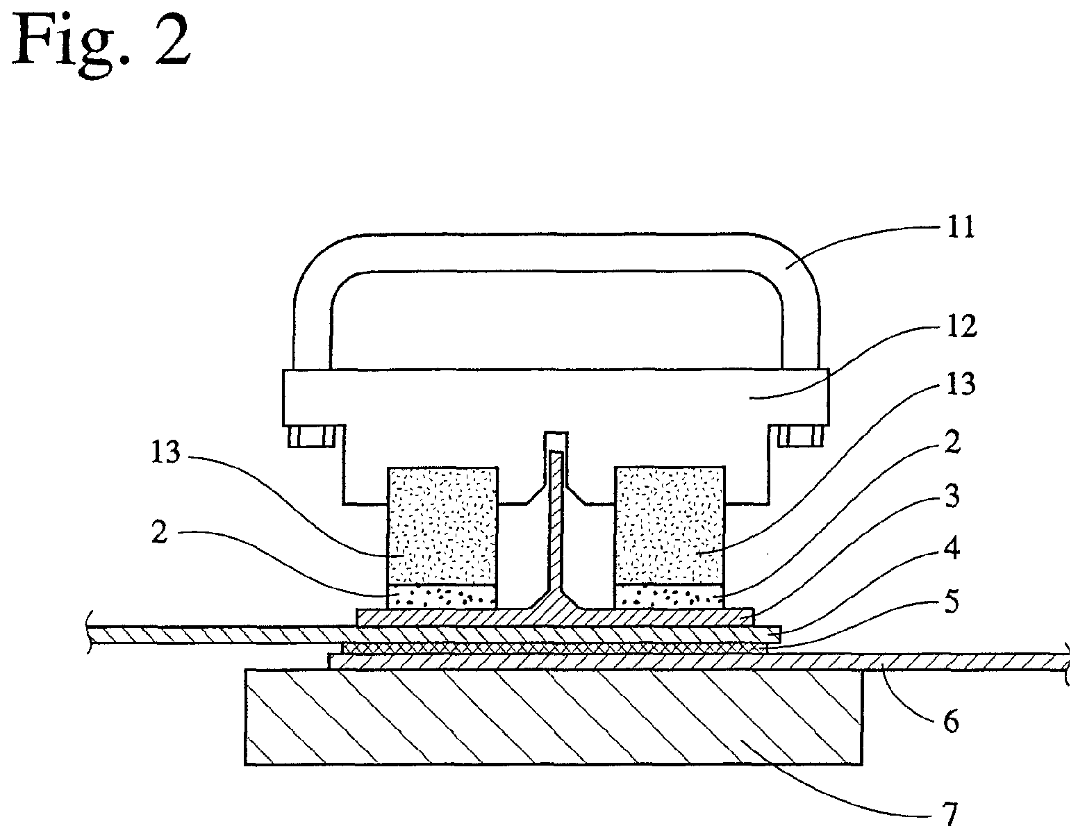
- Fig. 2 is a schematic view showing a state where the mated portions of half-cylindrical skin portions are pressed by a method for bonding non-magnetic members in accordance with the present invention.
-
- A method for bonding a plurality of non-magnetic members in accordance with the present invention comprises the steps of:
- (1) mating the non-magnetic members via an uncured adhesive interposed between their surfaces to be bonded;
- (2) applying pressure to the mated portions of the non-magnetic members between a pressing magnet jig and a pressure-receiving, soft-magnetic jig; and
- (3) curing the adhesive while applying pressure.
-
- The non-magnetic members are desirably made of lightweight materials of the same or different types such as fiber-reinforced composite materials, aluminum alloys, etc. Though not restrictive, the non-magnetic members may be in the shapes of a panel, pipe, box or combinations thereof. It is recommended that the fiber-reinforced composite material be made by impregnating reinforcing fibers such as carbon fibers, glass fibers, aramide fibers, etc. with synthetic resins (for example, polyesters, epoxy resins, bismalimide resins, phenolic resins, melamine resins, or silicon resins) and curing them.
- The bonding of the fiber-reinforced composite structures using a pressing magnet jig will hereinafter be described in detail with reference to the accompanying drawings. Figs. 1 and 2 show an embodiment in which half-cylindrical skin members made of a fiber-reinforced composite material for constituting a fuselage of aircraft are bonded to each other. The
pressing magnet jig 1 comprises ahandle 11 made of a soft-magnetic material, ajig body 12 made of a soft-magnetic material, andmagnet members 13. Areference numeral 7 denotes a pressure-receiving, soft-magnetic jig pairing with the pressingmagnet jig 1. Thereference numerals adhesive sheet 5. It should be noted that the shapes of the portions to be bonded are not limited to this embodiment, and that the portions to be bonded may be of any other shape or combination thereof. - Two half-
cylindrical skin members adhesive sheet 5 between their mated portions. The number of the uncured adhesive sheets inserted between the mated portions is preferably selected depending on a gap of the mated portions, though one adhesive sheet is usually preferable. An excessive number of uncured adhesive sheets are not preferable because they degrade the accuracy of dimension when assembling the half-cylindrical skin members - Though not restrictive, an adhesive is preferably used for bonding the structural members of aircraft, because the adhesive slightly creeps when a large load is applied thereto and has resistance to heat and solvents such as water, oil, gasoline, etc. The adhesive is preferably of a thermosetting type such as a thermosetting epoxy-based, phenol-based, or resorcinol-based adhesive, and this adhesive may be mixed with synthetic rubbers or thermoplastic resins.
- Although the adhesive may be applied in the form of liquid, it is applied preferably in the form of a sheet. When this kind of thermosetting adhesive or adhesive sheet is used, it preferably has a curing temperature lower than the heat resistance temperature of a magnet. For example, AF163-2K (curing temperature: 120°C) available from Minnesota Mining and Manufacturing Co. of the U.S., and FM300-2 (curing temperature: 120°C to 180°C) available from Cytec Fiberite Co. of the U.S. may be preferably used.
- The mated portions of the half-cylindrical skin members are sandwiched by the pressing
magnet jig 1 and the pressure-receiving, soft-magnetic jig 7 and pressed therebetween by an attractive force of the magnet in thepressing jig 1 to the soft-magnetic member in the pressure-receivingjig 7. - First, the pressure-receiving, soft-
magnetic jig 7 is put into contact with the outside surface of the portion to be bonded of the half-cylindrical skin member 6. Preferably, the surface of pressure-receiving, soft-magnetic jig 7 is shaped at least along the outside surface of the portion to be bonded of the half-cylindrical skin member 6. Next, the pressing magnet jig 1 pairing with the pressure-receiving, soft-magnetic jig 7 is put into contact with the outside surface of the portion to be bonded. Preferably, the pressure-applying surface of thepressing magnet jig 1 is shaped at least along the outside surface of the portion to be bonded of the half-cylindrical skin member 4. - Instead of the pressure-receiving, soft-
magnetic jig 7, anotherpressing magnet jig 1 may be used to generate an attractive force between both pressing magnet jigs. - The size and magnetic force of the magnet are selected such that it applies a pressure of 0.025 kg/cm2 to 0.8 kg/cm2, more preferably 0.2 kg/cm2 to 0.6 kg/cm2 to the mated portions, depending on the thickness and area of the mated portions and the type of the non-magnetic material. If the pressure is less than 0.025 kg/cm2, the bonding force becomes too small because the bonding surfaces are not put into uniform contact with the adhesive sheet, resulting in a likelihood that the
pressing magnet jig 1 and the pressure-receiving, soft-magnetic jig 7 may be detached by their own weights. Although the upper limit of pressure is not restrictive, pressure larger than 0.8 kg/cm2 makes it difficult to detach the jigs, while saturating increase in bonding strength. - The magnet is preferably a permanent magnet from the viewpoint of workability. Further, in the case of using a thermosetting adhesive, it is preferable that the heat resistance temperature of the magnet is not less than 130°C.
- Preferable as a magnet satisfying such requirements is NEOMAX-30SH (heat resistance temperature: 140°C) available from Sumitomo Special Metals Co. Ltd. The
jig body 12 made of a soft-magnetic material and thehandle 11 is preferably attached to a pair ofmagnets 13 as shown in Fig. 1 to easily handle themagnets 13. Fig. 2 shows a soft-magnetic jig body 12 utilizing the shape of astringer portion 3 made of a fiber-reinforced composite material to determine a bonding position. It should be noted that the shapes of the magnet and the soft-magnetic jig are not limited to those exemplified, and that they may be of any other shape. - To make the magnet form a circumferential magnetic path and to apply pressure to the whole bonding surface, a pair of permanent magnets are preferably fixed to the soft-magnetic jig with their magnetic poles opposed as is shown by the
reference number 13 in Figs. 1 and 2. - To facilitate the detachment of the
pressing magnet jig 1 from the bonded members and to improve the conformability of thepressing jig 1 to the shape of the portion to be bonded, one ormore cushioning members 2 are preferably interposed between the pressing surface of thepressing magnet jig 1 and the outside surface of the mated portion of the half-cylindrical skin member 6. A silicone or tetrafluorocarbon sheet is preferably used as the cushioningmember 2. Although the thickness of the cushioningmember 2 is not limited to a specific one, it is preferably 1 mm to 3 mm. In the case of using the cushioningmember 2, the magnetic force of the magnet is preferably selected such that pressure ranges from 0.025 kgf/mm2 to 0.8 kgf/mm2 in a state where the cushioningmember 2 is interposed. - Fastening members such as pins, bolts and nuts, rivets, sheet clamps for determining a bonding position are preferably used in minimum numbers before the
pressing magnet jig 1 abuts the pressure-receiving, soft-magnetic jig 7 via the non-magnetic members to be bonded. However, the use of an excessive number of pins, etc. should be avoided because it increases the number of man-hours. - As shown in Fig. 2, the thermosetting
adhesive sheet 5 is heated to a temperature necessary for curing while applying pressure to the mated portions. A heating unit is not restrictive. Though the mated portions may be locally heated with hot air, etc., the local heating of the mated portions may result in the breakage of the fiber-reinforced composite members or their mated portions by thermal expansion in some cases. Thus, it is preferable to heat the entire fiber-reinforced composite members uniformly using a uniform-temperature furnace. The heating temperature need only be lower than the heat resistance temperature of the magnet and high enough to thermally cure the adhesive sheet, though it preferably ranges from 100°C to 130°C, more preferably from 110°C to 120°C. If the heating temperature is lower than 110°C, the curing of the adhesive sheet is not complete, failing to produce sufficient bonding strength. - The bonding surfaces need only be heated while applying pressure for a time necessary for fully curing the adhesive to sufficient bonding strength, though it is preferable to keep them at the heating temperature for about 60 minutes. In the case of large fiber-reinforced composite members, their heating and cooling may be carried out at a constant speed of 2-4°C/minute.
- When pins, etc. are used to position the mated portions, they may be removed from the portions bonded or may be left as they are, after the mated portions are bonded. In the case of removing the pins, the hole from which the pins are removed are covered with resins, etc. On the other hand, when the pins are left, the pins are covered with the same material described above to prevent the corrosion of the pins.
- While the method for bonding non-magnetic members in accordance with the present invention has been described with reference to the drawings, it should be noted that the present invention is not limited thereto. On the contrary, the present invention is intended to cover all alternatives, modifications and equivalents, which may be included within the scope of the invention defined by the claims appended hereto.
- As described above in detail, according to a method in accordance with present invention, it is possible to effectively bond a plurality of non-magnetic members by fewer man-hours.
Claims (10)
- A method for bonding a plurality of non-magnetic members (4,6) comprising the steps of:(1) mating non-magnetic members via an uncured adhesive (5) interposed between their surfaces to be bonded;(2) applying pressure to the mated portions of said non-magnetic members between a pressing magnet jig (1) and a pressure-receiving, soft-magnetic jig (7); and(3) curing said adhesive while applying pressure.
- The method for bonding a plurality of non-magnetic members (4,6) according to claim 1, wherein said adhesive (5) is a thermosetting adhesive in the form of a sheet.
- The method for bonding a plurality of non-magnetic members (4,6) according to claim 1 or 2, wherein a cushioning member (2) is interposed between a pressing surface of said pressing magnet jig (1) and outside surfaces of the mated portions of said non-magnetic members.
- The method for bonding a plurality of non-magnetic members (4,6) according to claim 3, wherein a silicone or tetrafluorocarbon sheet is used as the cushioning member (2).
- The method for bonding a plurality of non-magnetic members (4,6) according to any preceding claim, wherein a pressure of 0.025 kg/cm2 to 0.8 kg/cm2 is applied to the mated portions of said non-magnetic members.
- The method for bonding a plurality of non-magnetic members (4,6) according to claim 5, wherein said
- The method for bonding a plurality of non-magnetic members (4,6) according to any preceding claim, wherein said non-magnetic members are made of a fiber-reinforced composite material.
- The method for bonding a plurality of non-magnetic members (4,6) according to any preceding claim, wherein a pair of non-magnetic members are bonded together, and said non-magnetic members are half-cylindrical skin members made of a fiber-reinforced composite material for constituting a fuselage of aircraft.
- The method for bonding a plurality of non-magnetic members (4,6) according to any preceding claim, wherein the pressing magnet jig (1) comprises a permanent magnet.
- The method for bonding a plurality of non-magnetic members (4,6) according to any preceding claim, wherein additional fastening members such as: pins, bolts and nuts, rivets and sheet clamps, are used to determine a bonding position before the pressing magnet jig (1) abuts the pressure-receiving, soft-magnetic jig (7) via the non-magnetic members to be bonded.
Applications Claiming Priority (2)
| Application Number | Priority Date | Filing Date | Title |
|---|---|---|---|
| JP2000253053 | 2000-08-23 | ||
| JP2000253053A JP4577960B2 (en) | 2000-08-23 | 2000-08-23 | Non-magnetic member joining method |
Publications (2)
| Publication Number | Publication Date |
|---|---|
| EP1182243A1 true EP1182243A1 (en) | 2002-02-27 |
| EP1182243B1 EP1182243B1 (en) | 2005-04-20 |
Family
ID=18742206
Family Applications (1)
| Application Number | Title | Priority Date | Filing Date |
|---|---|---|---|
| EP01307185A Expired - Lifetime EP1182243B1 (en) | 2000-08-23 | 2001-08-23 | Method for bonding non-magnetic members |
Country Status (4)
| Country | Link |
|---|---|
| US (1) | US6986827B2 (en) |
| EP (1) | EP1182243B1 (en) |
| JP (1) | JP4577960B2 (en) |
| DE (1) | DE60110166T2 (en) |
Cited By (3)
| Publication number | Priority date | Publication date | Assignee | Title |
|---|---|---|---|---|
| CN100357093C (en) * | 2005-12-30 | 2007-12-26 | 珠海元盛电子科技有限公司 | Small press |
| CN109058253A (en) * | 2018-07-25 | 2018-12-21 | 中国航空工业集团公司西安飞行自动控制研究所 | A kind of gasket and the circular pieces coaxially device of be bonded adjustment and bonding Method of Adjustment |
| WO2024052708A1 (en) * | 2022-09-06 | 2024-03-14 | Kovacs Krisztian | Magnetic press, and method restoration of works of art, especially for correction of damages of paintings |
Families Citing this family (18)
| Publication number | Priority date | Publication date | Assignee | Title |
|---|---|---|---|---|
| US20050081909A1 (en) * | 2003-10-20 | 2005-04-21 | Paull James B. | Concentrating solar roofing shingle |
| US20090283946A1 (en) * | 2008-05-19 | 2009-11-19 | Gm Global Technology Operations, Inc. | Single-sided magnetic fixturing systems |
| US8079549B2 (en) * | 2008-06-30 | 2011-12-20 | EMBRAER—Empresa Brasileira de Aeronautica S.A. | Monolithic integrated structural panels especially useful for aircraft structures |
| GB0819159D0 (en) * | 2008-10-20 | 2008-11-26 | Airbus Uk Ltd | Joint between aircraft components |
| US9140283B2 (en) * | 2010-11-12 | 2015-09-22 | Raytheon Company | Adhesively-bonded structural composite joint utilizing shoulder-centered sleeves |
| US9555578B2 (en) | 2012-11-30 | 2017-01-31 | The Boeing Company | Transfer system and method for applying a film material to an elongate member |
| US9067374B2 (en) | 2012-11-30 | 2015-06-30 | The Boeing Company | Method and apparatus for applying film material to elongate members |
| US9676160B2 (en) | 2012-11-30 | 2017-06-13 | The Boeing Company | Holding system for elongate members |
| US9403328B1 (en) * | 2013-02-08 | 2016-08-02 | The Boeing Company | Magnetic compaction blanket for composite structure curing |
| US9242679B2 (en) | 2013-03-14 | 2016-01-26 | Honda Motor Co., Ltd. | Securing arrangement and method for vehicle components |
| CN104121256A (en) * | 2013-04-25 | 2014-10-29 | 鸿富锦精密工业(深圳)有限公司 | Fixing device for irregular product |
| JP2015082637A (en) * | 2013-10-24 | 2015-04-27 | 富士通株式会社 | Method of manufacturing component assembly and positioning device |
| US9156239B2 (en) | 2013-12-20 | 2015-10-13 | Bell Helicopter Textron Inc. | Method of manufacturing net edge core and a method of bonding net edge core to a substructure |
| US9211618B2 (en) * | 2013-12-20 | 2015-12-15 | Bell Helicopter Textron Inc. | Method of securing composite core during a manufacturing process |
| CN111230764B (en) * | 2018-11-28 | 2021-08-20 | 宁波方太厨具有限公司 | Bonding tool for panel assembly of range hood |
| CN111230763B (en) * | 2018-11-28 | 2021-08-20 | 宁波方太厨具有限公司 | A bonding tool for a range hood panel assembly |
| CN112109021B (en) * | 2020-09-30 | 2022-09-09 | 苏州富强科技有限公司 | Dead-weight press-fit head |
| CN115450998A (en) * | 2022-09-02 | 2022-12-09 | 中国航空救生研究所 | A large-scale structural component high temperature strain gauge pasting curing device and curing method |
Citations (5)
| Publication number | Priority date | Publication date | Assignee | Title |
|---|---|---|---|---|
| US2552285A (en) * | 1944-04-04 | 1951-05-08 | Union Carbide & Carbon Corp | Manufacture of composite material containing one or more aluminum components |
| US4478659A (en) * | 1981-11-24 | 1984-10-23 | Hall Alethea R M | Method of joining sheets of a non-magnetic material together |
| DE3827178C1 (en) * | 1988-08-10 | 1990-03-29 | Hans-Georg 8261 Aschau De Bischoff | Apparatus for producing joining seams between overlapping film parts |
| DE4126009A1 (en) * | 1991-08-06 | 1993-02-11 | Airbus Gmbh | Adhesive bonding for metal parts - uses tacking pins in prepared drillings to hold them together for adhesive application and hardening, e.g. for aircraft planking plates |
| DE19607061C1 (en) * | 1996-02-24 | 1997-05-15 | Eurocopter Deutschland | Adhesive bonding of fibre compound board materials |
Family Cites Families (15)
| Publication number | Priority date | Publication date | Assignee | Title |
|---|---|---|---|---|
| US1782615A (en) * | 1928-06-18 | 1930-11-25 | Carrie S Hopwood | Workholder |
| US2519107A (en) * | 1946-09-19 | 1950-08-15 | Wayne B Brown | Cushioning device for c-clamps |
| US2713379A (en) * | 1952-11-25 | 1955-07-19 | Firestone Tire & Rubber Co | Magnetic device for clamping overlapping parts during adhesive bonding |
| US2705084A (en) * | 1953-04-30 | 1955-03-29 | United States Steel Corp | Hold-down and bearing device for industrial trucks |
| US3322423A (en) * | 1964-06-24 | 1967-05-30 | Popow Anatoliy | Vise jaw cover plate |
| US3935055A (en) * | 1974-08-30 | 1976-01-27 | Nupla Corporation | Assembly tool for use in attaching fiberglass tool handles |
| US4135416A (en) * | 1977-10-18 | 1979-01-23 | Jean Roux | Tool for opening and closing wrist watches |
| US4335873A (en) * | 1980-05-21 | 1982-06-22 | C. J. Edwards Company | Toggle bolt clamp |
| JPS6219440A (en) * | 1985-07-19 | 1987-01-28 | Hitachi Zosen Corp | Molding of fuselage of airplane |
| JPH0513533Y2 (en) * | 1987-11-24 | 1993-04-09 | ||
| JPH05286493A (en) * | 1992-04-08 | 1993-11-02 | Honda Motor Co Ltd | Fuselage structure of an aircraft |
| JPH09241609A (en) * | 1996-03-04 | 1997-09-16 | Shinko Alcoa Yuso Kizai Kk | Adhesive for aluminum or aluminum alloy and joining thereof |
| JPH10264257A (en) | 1997-03-26 | 1998-10-06 | Sumitomo Metal Ind Ltd | Joining method of thermosetting laminated resin plate |
| CA2347717A1 (en) * | 1998-09-30 | 2000-04-06 | Toray Industries, Inc. | A fibre-reinforced resin structure having hollow cross section and manufacturing method thereof |
| JP4380909B2 (en) * | 2000-12-06 | 2009-12-09 | 本田技研工業株式会社 | Hollow structure made of fiber reinforced composite material and method for joining the reinforcement |
-
2000
- 2000-08-23 JP JP2000253053A patent/JP4577960B2/en not_active Expired - Fee Related
-
2001
- 2001-08-22 US US09/933,832 patent/US6986827B2/en not_active Expired - Fee Related
- 2001-08-23 DE DE60110166T patent/DE60110166T2/en not_active Expired - Lifetime
- 2001-08-23 EP EP01307185A patent/EP1182243B1/en not_active Expired - Lifetime
Patent Citations (5)
| Publication number | Priority date | Publication date | Assignee | Title |
|---|---|---|---|---|
| US2552285A (en) * | 1944-04-04 | 1951-05-08 | Union Carbide & Carbon Corp | Manufacture of composite material containing one or more aluminum components |
| US4478659A (en) * | 1981-11-24 | 1984-10-23 | Hall Alethea R M | Method of joining sheets of a non-magnetic material together |
| DE3827178C1 (en) * | 1988-08-10 | 1990-03-29 | Hans-Georg 8261 Aschau De Bischoff | Apparatus for producing joining seams between overlapping film parts |
| DE4126009A1 (en) * | 1991-08-06 | 1993-02-11 | Airbus Gmbh | Adhesive bonding for metal parts - uses tacking pins in prepared drillings to hold them together for adhesive application and hardening, e.g. for aircraft planking plates |
| DE19607061C1 (en) * | 1996-02-24 | 1997-05-15 | Eurocopter Deutschland | Adhesive bonding of fibre compound board materials |
Cited By (3)
| Publication number | Priority date | Publication date | Assignee | Title |
|---|---|---|---|---|
| CN100357093C (en) * | 2005-12-30 | 2007-12-26 | 珠海元盛电子科技有限公司 | Small press |
| CN109058253A (en) * | 2018-07-25 | 2018-12-21 | 中国航空工业集团公司西安飞行自动控制研究所 | A kind of gasket and the circular pieces coaxially device of be bonded adjustment and bonding Method of Adjustment |
| WO2024052708A1 (en) * | 2022-09-06 | 2024-03-14 | Kovacs Krisztian | Magnetic press, and method restoration of works of art, especially for correction of damages of paintings |
Also Published As
| Publication number | Publication date |
|---|---|
| DE60110166D1 (en) | 2005-05-25 |
| JP2002060721A (en) | 2002-02-26 |
| JP4577960B2 (en) | 2010-11-10 |
| US20020029847A1 (en) | 2002-03-14 |
| US6986827B2 (en) | 2006-01-17 |
| DE60110166T2 (en) | 2006-02-02 |
| EP1182243B1 (en) | 2005-04-20 |
Similar Documents
| Publication | Publication Date | Title |
|---|---|---|
| US6986827B2 (en) | Method for bonding non-magnetic members | |
| US5793024A (en) | Bonding using induction heating | |
| US8007628B2 (en) | Cellular composite grid-stiffened structure | |
| US20090095413A1 (en) | Composite reinforcement of metallic structural elements | |
| US6719865B2 (en) | Method for producing stiffened hollow structure composed of fiber-reinforced composite | |
| ES2185443A1 (en) | Process for manufacturing pre-cured parts of composite material with green-applied stiffeners | |
| EP2492083A2 (en) | Joint structure for fiber reinforced resin and metal, and joining method for fiber reinforced resin and metal | |
| US5849393A (en) | Structural element and method of making | |
| EP3132867B1 (en) | Apparatus and method for forming three-sheet panels | |
| US20240367396A1 (en) | Apparatus, system, and method for repairing composite sandwich panels | |
| US20080131656A1 (en) | System, method, and apparatus for structural lug formed from a combination of metal and composite laminate materials | |
| CN111873575A (en) | Integrated structure of heterogeneous materials and method for integrating heterogeneous materials | |
| US7138031B2 (en) | Mandrel and method for manufacturing composite structures | |
| US11760043B2 (en) | High strength mechanical fastening inclusions for fiber reinforced polymer structures | |
| US7574835B2 (en) | Composite-to-metal joint | |
| CN105538693A (en) | Reinforced moldable rivet assembly for a vehicle | |
| EP4159415B1 (en) | Method for joining fibre reinforced composite parts using friction stir welding along a butt joint, aircraft component and aircraft | |
| US7921893B2 (en) | Method and apparatus for welding of polymer composite components | |
| US20180169961A1 (en) | System and method for bonding structures | |
| KR101558208B1 (en) | Spot welding method of panel | |
| JPS63230323A (en) | Bonding method of structural member | |
| EP0950507B1 (en) | Localized pressure and heat apparatuses | |
| US20230234301A1 (en) | Method for surface structuring | |
| CN117480089A (en) | Plastic component for a motor vehicle, component composite for a motor vehicle, method for producing a plastic component for a motor vehicle and method for producing a component composite for a motor vehicle | |
| JP2021017127A (en) | Structure of movable body, and method of manufacturing the same |
Legal Events
| Date | Code | Title | Description |
|---|---|---|---|
| PUAI | Public reference made under article 153(3) epc to a published international application that has entered the european phase |
Free format text: ORIGINAL CODE: 0009012 |
|
| AK | Designated contracting states |
Kind code of ref document: A1 Designated state(s): DE FR GB Kind code of ref document: A1 Designated state(s): AT BE CH CY DE DK ES FI FR GB GR IE IT LI LU MC NL PT SE TR |
|
| AX | Request for extension of the european patent |
Free format text: AL;LT;LV;MK;RO;SI |
|
| 17P | Request for examination filed |
Effective date: 20020816 |
|
| AKX | Designation fees paid |
Free format text: DE FR GB |
|
| 17Q | First examination report despatched |
Effective date: 20021216 |
|
| GRAP | Despatch of communication of intention to grant a patent |
Free format text: ORIGINAL CODE: EPIDOSNIGR1 |
|
| RIN1 | Information on inventor provided before grant (corrected) |
Inventor name: SATO, KEIICHI Inventor name: MATSUI, NOBUO Inventor name: KASAHARA, YUKI Inventor name: NASU, MAKOTO |
|
| GRAS | Grant fee paid |
Free format text: ORIGINAL CODE: EPIDOSNIGR3 |
|
| GRAA | (expected) grant |
Free format text: ORIGINAL CODE: 0009210 |
|
| AK | Designated contracting states |
Kind code of ref document: B1 Designated state(s): DE FR GB |
|
| REG | Reference to a national code |
Ref country code: GB Ref legal event code: FG4D |
|
| REG | Reference to a national code |
Ref country code: IE Ref legal event code: FG4D |
|
| REF | Corresponds to: |
Ref document number: 60110166 Country of ref document: DE Date of ref document: 20050525 Kind code of ref document: P |
|
| PLBE | No opposition filed within time limit |
Free format text: ORIGINAL CODE: 0009261 |
|
| STAA | Information on the status of an ep patent application or granted ep patent |
Free format text: STATUS: NO OPPOSITION FILED WITHIN TIME LIMIT |
|
| ET | Fr: translation filed | ||
| 26N | No opposition filed |
Effective date: 20060123 |
|
| PGFP | Annual fee paid to national office [announced via postgrant information from national office to epo] |
Ref country code: DE Payment date: 20140821 Year of fee payment: 14 |
|
| PGFP | Annual fee paid to national office [announced via postgrant information from national office to epo] |
Ref country code: GB Payment date: 20140820 Year of fee payment: 14 Ref country code: FR Payment date: 20140808 Year of fee payment: 14 |
|
| REG | Reference to a national code |
Ref country code: DE Ref legal event code: R119 Ref document number: 60110166 Country of ref document: DE |
|
| GBPC | Gb: european patent ceased through non-payment of renewal fee |
Effective date: 20150823 |
|
| REG | Reference to a national code |
Ref country code: FR Ref legal event code: ST Effective date: 20160429 |
|
| PG25 | Lapsed in a contracting state [announced via postgrant information from national office to epo] |
Ref country code: DE Free format text: LAPSE BECAUSE OF NON-PAYMENT OF DUE FEES Effective date: 20160301 Ref country code: GB Free format text: LAPSE BECAUSE OF NON-PAYMENT OF DUE FEES Effective date: 20150823 |
|
| PG25 | Lapsed in a contracting state [announced via postgrant information from national office to epo] |
Ref country code: FR Free format text: LAPSE BECAUSE OF NON-PAYMENT OF DUE FEES Effective date: 20150831 |