EP1182124A2 - Tretroller - Google Patents
Tretroller Download PDFInfo
- Publication number
- EP1182124A2 EP1182124A2 EP00124375A EP00124375A EP1182124A2 EP 1182124 A2 EP1182124 A2 EP 1182124A2 EP 00124375 A EP00124375 A EP 00124375A EP 00124375 A EP00124375 A EP 00124375A EP 1182124 A2 EP1182124 A2 EP 1182124A2
- Authority
- EP
- European Patent Office
- Prior art keywords
- shaft
- drive
- chassis
- drive pulley
- pulley
- Prior art date
- Legal status (The legal status is an assumption and is not a legal conclusion. Google has not performed a legal analysis and makes no representation as to the accuracy of the status listed.)
- Withdrawn
Links
Images


Classifications
-
- B—PERFORMING OPERATIONS; TRANSPORTING
- B62—LAND VEHICLES FOR TRAVELLING OTHERWISE THAN ON RAILS
- B62M—RIDER PROPULSION OF WHEELED VEHICLES OR SLEDGES; POWERED PROPULSION OF SLEDGES OR SINGLE-TRACK CYCLES; TRANSMISSIONS SPECIALLY ADAPTED FOR SUCH VEHICLES
- B62M1/00—Rider propulsion of wheeled vehicles
- B62M1/24—Rider propulsion of wheeled vehicles with reciprocating levers, e.g. foot levers
- B62M1/28—Rider propulsion of wheeled vehicles with reciprocating levers, e.g. foot levers characterised by the use of flexible drive members, e.g. chains
-
- B—PERFORMING OPERATIONS; TRANSPORTING
- B62—LAND VEHICLES FOR TRAVELLING OTHERWISE THAN ON RAILS
- B62K—CYCLES; CYCLE FRAMES; CYCLE STEERING DEVICES; RIDER-OPERATED TERMINAL CONTROLS SPECIALLY ADAPTED FOR CYCLES; CYCLE AXLE SUSPENSIONS; CYCLE SIDE-CARS, FORECARS, OR THE LIKE
- B62K3/00—Bicycles
- B62K3/002—Bicycles without a seat, i.e. the rider operating the vehicle in a standing position, e.g. non-motorized scooters; non-motorized scooters with skis or runners
Definitions
- the present invention relates to a scooter and, more particularly, to a scooter which can be propelled forward continuously.
- a scooter is a vehicle for a child to stand on by one foot and to propel it by the other foot touching the ground.
- a scooter typically includes a head tube (70) formed at a front end of a narrow board (71), with a front wheel (72) steerably attached to the head tube (70) and a rear wheel (73) rotatably attached to a rear end of the board (70).
- the conventional scooter Because it is pushed forward only at each time the other foot touches the ground, the conventional scooter is propelled intermittently and is moved forward at a relative slow speed.
- the object of the present invention is to provide a scooter which can be propelled forward continuously.
- Another object of the present invention is to provide a scooter which can provide an exiting sport for leisure enjoyment.
- Still another object of the present invention is to provide a scooter which has high safety.
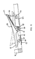
- a scooter in accordance with the present invention includes a chassis (11) having a front end and a rear end.
- the chassis (11) preferably has a head tube (10) formed at the front end thereof.
- a front wheel (not numbered) is steerably attached to the front end of the chassis (11) or to the head tube (10), such as by way of a front fork, and a rear wheel (12) is rotatably attached to the rear end of the chassis (11).
- the scooter further includes an elongated pedal (20) disposed longitudinally above the chassis (11),
- the pedal (20) has a backward end (21) and a forward end (22), with a pair of downwardly extending wings (23) formed between the ends (21, 22) thereof.
- the pedal (20) is pivotally connected to the chassis (11), by means of a first shaft (31) which laterally extends through the chassis (11) and the wings (23), so that the pedal (20) may sway forward and backward relative to the chassis (11), as shown in Fig. 1.
- the first shaft (31) is rotatably supported on the chassis (11). Being similar to a bicycle, there are provided a driving sprocket (32) securely mounted around the first shaft (31) and a driven sprocket (13) securely attached to a center of the rear wheel (12), with a primary chain (33) around the sprockets (32, 13) to transmit rotation from the first shaft (31) to the rear wheel (12). In this manner, the scooter is moved forward when the first shaft (31) is rotated relative to the chassis (11) in a correct direction, which is counterclockwise as view from Fig. 1.
- the terms 'correct direction' is referred to a direction in which the first shaft (31, 50) is rotated to drive the driven sprocket (13) in such a way that the vehicle is moved forward, as mentioned above, and the terms 'normal direction' is referred to the same direction of other parts of the scooter.
- a preferred embodiment of the means (30) include a first sprocket (36), a second sprocket (45) and a third sprocket (42) mounted around respective first, second and third shafts (31, 44, 40), among which the second and third shafts (44, 40) also laterally extend through and rotatably supported on the chassis (11), except that the second one is in front of and the third one is behind the first shaft (31).
- Each of the first and third sprockets (36, 42) is formed with a one-way mechanism (35, 41), such as a racket gearing, unidirectional bearing and the like, that couples the sprocket (36, 42) to the associated shaft (31, 40) when the sprocket (36, 42) is rotated in the normal direction and uncouples the sprocket (36, 42) from the associated shaft (31, 40) when the sprocket (36, 42) is rotated in the opposite direction.
- a one-way mechanism 35, 41
- a racket gearing such as a racket gearing, unidirectional bearing and the like
- first secondary chain (46) running around a top edge of the first sprocket (36) and bottom edges of the second and third sprockets (45, 42), with two ends of the chain (46) attached to the ends (21, 22) of the pedal (20), as shown in Fig. 1,
- the arrangement of the first secondary chain (46) enables the sprockets (36, 45, 42) to be rotated with the swaying motion of the pedal (20), especially the first and third sprockets (36, 42) to be rotated in opposite directions --- alternatively for each of them (36, 42) and relatively one with respect to another.
- the sprockets (36, 42) are thus complementarily coupled to their associated shafts (31, 40) due to their one-way mechanisms (33, 41), resulting in rotation of alternative one of the first and third shafts (31, 40) in the correct or the normal direction.
- the embodiment of the means (30) further include a fourth sprocket (34) securely mounted around the first shaft (31) at a side of the first sprocket (36), a fifth sprocket (420) securely mounted around the third shaft (40) at a side of the third sprocket (42) and a second secondary chain (43) around the fourth and fifth sprockets (34, 420), thereby additionally transmitting the correct rotation from the third shaft (40) to the first shaft (31).
- the inventive scooter can be moved forward by a player (not shown) who stands on the pedal (20) with his/her feet on the ends (21, 22) to sway the pedal (20) like a seesaw.
- first sprocket (36) is coupled to the first shaft (31) and the third sprocket (42) is uncoupled from the third shaft (40), as mentioned above.
- the first shaft (31) is thus rotated in the correct direction with the first sprocket (36), and so the scooter is moved forward.
- the first sprocket (36) is uncoupled from the first shafl (31) and the third sprocket (42) is coupled to the third shaft (40), which is hence rotated with the third sprocket (42).
- the first shift (31) is then rotated in the correct direction by the very third shaft, through the second secondary chain (43) around the fourth and fifth sprockets, and so the scooter is moved formed.
- an alternative embodiment of the means (30) include a pair of sprockets (53, 52) mounted around the first shaft (50) side by side, with each sprocket (52, 53) having a one-way mechanisms (51) that couples the sprocket (52, 53) to the first shaft (50) when the sprocket (52, 53) is rotated in the normal direction and uncouples the sprocket (52, 53) from the first shaft (50) when the sprocket (52, 53) is rotated in the opposite direction.
- first secondary chain (46) has a first attached to the forward end (22) of the pedal (20), and a second end attached to a spring member (63) that is in turn connected to the chassis (11) substantially under the forward end (22) of the pedal (20), as shown in Fig. 6.
- a fourth sprocket (64) rotatably connected to the chassis (11), such as by a third shaft (40), and a second secondary chain (65) running around a bottom edge of the fourth sprockets (64) and a front edge of the second sprocket (52).
- the second secondary chain (65) has a first end attached to the backward end (21) of the pedal (20), and a second end attached to a second spring member (66) that is in turn connected to the backward end (21) of the pedal (20).
- This arrangement of the secondary chains (62, 65) also enables the sprockets (52, 53, 61, 64) to be rotated with the swaying motion of the pedal (20), especially the first and second sprockets (53, 52) to be rotated in opposite directions, and so the sprockets (53, 52) are complementarily coupled to the first shaft (50) due to the one-way mechanisms (51), resulting in rotation of the first shaft (50) invariably (31, 40) in the correct direction.
- the front end (22) goes up, as shown in dash line in Fig. 6.
- the first secondary chain (62) is pulled, by stretching the spring member (63), in such a direction that the first sprocket (53) is rotated in the normal direction.
- the first sprocket (53) is then coupled to the first shaft (50) due to its one-way mechanism (51).
- the first shaft (50) is rotated in the correct direction with the first sprocket (53), thereby propelling the scooter forward.
- the inventive scooter can be moved forward by the player standing thereon with his/her feet pressing the ends (21, 22) of the pedal (20) alternatively and repeatedly.
- the chain (33, 43, 46, 62, 65) may be embodied as any flexible drive piece, such as a belt
- the sprocket (13, 32, 36, 45, 42, 34, 420, 53, 52, 61, 64) may be embodied as any pulley or drive pulley, such as a belt pulley, that is configured to mate with the flexible drive piece.
- the scooter can be propelled continuously and can be moved forward at a relative high speed.
- the scooter is stable in movement and has high safety.
Landscapes
- Engineering & Computer Science (AREA)
- Mechanical Engineering (AREA)
- Chemical & Material Sciences (AREA)
- Combustion & Propulsion (AREA)
- Transportation (AREA)
- Motorcycle And Bicycle Frame (AREA)
- Steering Devices For Bicycles And Motorcycles (AREA)
- Automatic Cycles, And Cycles In General (AREA)
Applications Claiming Priority (2)
| Application Number | Priority Date | Filing Date | Title |
|---|---|---|---|
| DE10041761 | 2000-08-25 | ||
| DE2000141761 DE10041761A1 (de) | 2000-08-25 | 2000-08-25 | Roller |
Publications (2)
| Publication Number | Publication Date |
|---|---|
| EP1182124A2 true EP1182124A2 (de) | 2002-02-27 |
| EP1182124A3 EP1182124A3 (de) | 2003-07-23 |
Family
ID=7653757
Family Applications (1)
| Application Number | Title | Priority Date | Filing Date |
|---|---|---|---|
| EP00124375A Withdrawn EP1182124A3 (de) | 2000-08-25 | 2000-11-20 | Tretroller |
Country Status (2)
| Country | Link |
|---|---|
| EP (1) | EP1182124A3 (de) |
| DE (1) | DE10041761A1 (de) |
Family Cites Families (4)
| Publication number | Priority date | Publication date | Assignee | Title |
|---|---|---|---|---|
| US907562A (en) * | 1908-04-17 | 1908-12-22 | John W P Boettcher | Vehicle. |
| FR568787A (fr) * | 1923-01-30 | 1924-04-01 | Trottinette mue par levier à pédales | |
| US1558851A (en) * | 1925-05-18 | 1925-10-27 | Labrot S Edwards | Teeter car |
| US4186934A (en) * | 1978-09-27 | 1980-02-05 | Collings Thomas J | Scooter vehicle |
-
2000
- 2000-08-25 DE DE2000141761 patent/DE10041761A1/de not_active Withdrawn
- 2000-11-20 EP EP00124375A patent/EP1182124A3/de not_active Withdrawn
Non-Patent Citations (1)
| Title |
|---|
| None |
Also Published As
| Publication number | Publication date |
|---|---|
| DE10041761A1 (de) | 2002-06-13 |
| EP1182124A3 (de) | 2003-07-23 |
Similar Documents
| Publication | Publication Date | Title |
|---|---|---|
| US6419251B1 (en) | Propelling scooter | |
| US6398244B1 (en) | Propelling scooter | |
| US8272655B2 (en) | Mini bike having pedal as a power generator | |
| US4779863A (en) | Running exercise bicycle | |
| US6857648B2 (en) | Pedal scooter | |
| US6311998B1 (en) | Geared scooter | |
| US4200304A (en) | Twisting car | |
| US10843767B2 (en) | Dual pedal-driven scooter | |
| US20100044995A1 (en) | Quick board with handle to operate driving power of front wheel | |
| EP1420999A1 (de) | Steuersystem eines mobilen teiles, lenksystem für leichte fahrzeuge und dreirad mit einem solchen system | |
| US3086795A (en) | Occupant propelled scooter | |
| US4783091A (en) | Apparatus for exercise and recreation | |
| US3118514A (en) | Front wheel drive for two wheeled vehicle | |
| EP1182124A2 (de) | Tretroller | |
| EP3762112A1 (de) | Handbetriebenes manuelles laufband | |
| EP1225124A1 (de) | Antreibbarer Roller | |
| US2062830A (en) | Self-propelling scooter | |
| US20020105160A1 (en) | Man-powered vehicle | |
| WO2004083028A1 (en) | Drivable scooter with footstools | |
| KR100927202B1 (ko) | 전륜의 구동력을 손잡이에 의해 운행되도록 하는 퀵보드 | |
| KR100642140B1 (ko) | 전후륜 자전운행이 가능한 퀵보드 | |
| CN110789647A (zh) | 一种滑板车 | |
| KR200251024Y1 (ko) | 유희용 자전거 | |
| US1529952A (en) | Vehicle toy | |
| CN2161546Y (zh) | 脚踏车 |
Legal Events
| Date | Code | Title | Description |
|---|---|---|---|
| PUAI | Public reference made under article 153(3) epc to a published international application that has entered the european phase |
Free format text: ORIGINAL CODE: 0009012 |
|
| AK | Designated contracting states |
Kind code of ref document: A2 Designated state(s): AT BE CH CY DE DK ES FI FR GB GR IE IT LI LU MC NL PT SE TR |
|
| AX | Request for extension of the european patent |
Free format text: AL;LT;LV;MK;RO;SI |
|
| PUAL | Search report despatched |
Free format text: ORIGINAL CODE: 0009013 |
|
| AK | Designated contracting states |
Designated state(s): AT BE CH CY DE DK ES FI FR GB GR IE IT LI LU MC NL PT SE TR |
|
| AX | Request for extension of the european patent |
Extension state: AL LT LV MK RO SI |
|
| AKX | Designation fees paid | ||
| REG | Reference to a national code |
Ref country code: DE Ref legal event code: 8566 |
|
| STAA | Information on the status of an ep patent application or granted ep patent |
Free format text: STATUS: THE APPLICATION IS DEEMED TO BE WITHDRAWN |
|
| 18D | Application deemed to be withdrawn |
Effective date: 20040124 |