EP1180837A1 - Gehäuse für Elektroinstallationseinrichtungen - Google Patents
Gehäuse für Elektroinstallationseinrichtungen Download PDFInfo
- Publication number
- EP1180837A1 EP1180837A1 EP01118078A EP01118078A EP1180837A1 EP 1180837 A1 EP1180837 A1 EP 1180837A1 EP 01118078 A EP01118078 A EP 01118078A EP 01118078 A EP01118078 A EP 01118078A EP 1180837 A1 EP1180837 A1 EP 1180837A1
- Authority
- EP
- European Patent Office
- Prior art keywords
- housing
- hollow profile
- wall
- housing according
- edge
- Prior art date
- Legal status (The legal status is an assumption and is not a legal conclusion. Google has not performed a legal analysis and makes no representation as to the accuracy of the status listed.)
- Granted
Links
- 230000002093 peripheral effect Effects 0.000 claims description 8
- 238000010616 electrical installation Methods 0.000 claims description 4
- 238000002347 injection Methods 0.000 claims description 4
- 239000007924 injection Substances 0.000 claims description 4
- 230000000087 stabilizing effect Effects 0.000 claims description 3
- 239000000463 material Substances 0.000 description 9
- 238000009826 distribution Methods 0.000 description 7
- 238000000034 method Methods 0.000 description 4
- 238000007373 indentation Methods 0.000 description 3
- 238000009434 installation Methods 0.000 description 3
- 238000009825 accumulation Methods 0.000 description 1
- 230000000694 effects Effects 0.000 description 1
- 238000001746 injection moulding Methods 0.000 description 1
- 230000010354 integration Effects 0.000 description 1
- 238000004519 manufacturing process Methods 0.000 description 1
- 239000011505 plaster Substances 0.000 description 1
- 238000007711 solidification Methods 0.000 description 1
- 230000008023 solidification Effects 0.000 description 1
- 238000005507 spraying Methods 0.000 description 1
- 239000003351 stiffener Substances 0.000 description 1
- 230000008719 thickening Effects 0.000 description 1
Images



Classifications
-
- H—ELECTRICITY
- H02—GENERATION; CONVERSION OR DISTRIBUTION OF ELECTRIC POWER
- H02B—BOARDS, SUBSTATIONS OR SWITCHING ARRANGEMENTS FOR THE SUPPLY OR DISTRIBUTION OF ELECTRIC POWER
- H02B1/00—Frameworks, boards, panels, desks, casings; Details of substations or switching arrangements
- H02B1/26—Casings; Parts thereof or accessories therefor
- H02B1/40—Wall-mounted casings; Parts thereof or accessories therefor
-
- H—ELECTRICITY
- H02—GENERATION; CONVERSION OR DISTRIBUTION OF ELECTRIC POWER
- H02B—BOARDS, SUBSTATIONS OR SWITCHING ARRANGEMENTS FOR THE SUPPLY OR DISTRIBUTION OF ELECTRIC POWER
- H02B1/00—Frameworks, boards, panels, desks, casings; Details of substations or switching arrangements
- H02B1/015—Boards, panels, desks; Parts thereof or accessories therefor
Definitions
- the invention relates to a housing for electrical installation devices, in particular distributors, Counter spaces and the like.
- a relatively large number of meter space enclosures, distribution boxes, distribution cabinets required and other housings for electrical installation devices are known to be today Injection molded from insulating plastic material.
- the present invention has for its object a new housing for electrical installation devices to create that compared with the same or increased stability Conventional such housings require less plastic material.
- the housing that achieves this object according to the invention is characterized by a connected to the housing, the housing stabilizing hollow profile.
- Hollow profile can give the housing high strength even with a small wall thickness to lend. It is also advantageous for the hollow profile itself in comparison to stiffeners how stiffening ribs are formed by simply thickening the housing wall, relatively little material needed. In particular, a material accumulation can be achieved through a hollow profile avoid the risk of sink marks on the housing surface contains, which severely impair the appearance of such a plastic housing can.
- the hollow profile extends at least in sections along the edge of a housing wall, it being particularly direct adjacent to the edge of the housing wall and preferably frame-like around the housing wall circulates.
- a housing wall e.g. on the front wall of a distributor housing cover or the Back wall of a distributor housing formed hollow frame profile can for a high Torsional rigidity of the housing parts cause and affect, even if it extends into the housing interior seen in cross section, due to its Arrangement on the edge of the housing barely the for mounting electrical equipment in mounting space usable in the housing.
- the cross section of the hollow profile can of course also extend outwards from the housing extend so that no assembly space is lost inside the housing.
- the hollow profile is in a housing wall integrated that it is formed over part of its circumference by the housing wall itself is.
- the hollow profile in the corner region of housing walls that are at an angle to one another be educated, e.g. in the corner area between a rear wall and the Housing side walls, the hollow profile through the angularly abutting housing walls and a peripheral portion connecting the housing walls is formed.
- Such a peripheral section can be used to form a hollow profile having three corners be straight or curved according to a circular line.
- Such a peripheral portion of the Hollow profile then forms a chamfer or rounded corner inside the housing, by which the size of the housing interior volume is only slight and in particular only in a space that is hardly needed for the installation of installation equipment reduced.
- the hollow profiles can be created using the well-known GID method which the workpiece in the injection mold before the complete solidification of an internal gas pressure is subjected.
- the hollow profile can also be at a distance from the edge extend a housing wall along the wall surface.
- a housing cover one not shown otherwise Distributor housing made of plastic, which e.g. installable under plaster Distribution box for the connection rails. safety devices etc. has.
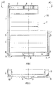
- the housing cover 1 shown with a cutout at 50 has a front wall 2, in windows 3 and 4 for access to the safety devices arranged in the junction box are formed.
- Longitudinal side walls 5 extend perpendicular to the front wall 2 of the housing cover 1 and 6 and narrow side walls 7 and 8.
- windows 3 and 4 are on the front wall 2 at the top and bottom of each other opposite indentations 9 and 10 formed, from which disc-like handle parts 11 and 12 protrude.
- a bolt guide is formed, one of which 1 and 3, the guides 13 to 15 are visible. There are bolts in the bolt guides to attach the housing cover 1 to the junction box.
- the head of this Bolzen has a laterally protruding beard.
- tabs 16 and 17 are formed, of which the Pin 16 in Fig. 3 and the pin 17 in Fig. 5 is visible.
- the housing cover 1 can be snapped into the distribution box mentioned above.
- the housing cover 1 designates integrated hollow profiles, the frame-like at the edge of the front wall 2 circulate, the frame formed by the hollow profiles 18 and 19 at 20 and 21, that is, in the area of the indentations 9 and 10, is interrupted.
- the hollow profile is in the corner area of each of the side walls 5 to 8 and the front wall 2 of the housing cover 1, wherein, as in particular from FIG. 4 and 5 emerges, a profile leg 23 through the front wall 2 of the housing cover 1 and a profile leg 24 is formed by one of the side walls 5 to 8 of the housing cover 1.
- the hollow profile 18 or 19 away from the side walls and around respective bolt guide passed around, as can be seen in particular from FIGS. 6 and 7 is, in this section of the hollow profile a profile leg 23 'through in this area stepped front wall 2 of the housing cover 1 is formed.
- the profile leg 25 corresponds here to a profile leg 25 ', and it is another protruding into the interior of the housing Profile leg 26 provided.
- the reference numerals 31 and 32 are in the manufacture of the housing cover by plastic injection molding Designated openings used, through which during the spraying process the material that has already solidified on the outer skin is subjected to an internal pressure Compressed gas is subjected such that the hollow profiles 18, 19 form.
- Compressed gas is subjected such that the hollow profiles 18, 19 form.
- GID process known pressurization the compressed gas creates the cavity of the Hollow profile and ensures a material expansion, whereby the plastic material under the effect of the internal pressure in the tool area forming the hollow profiles against the inner wall of the injection mold.
- the hollow profiles are arranged in a space-saving manner in the corner area on the edge of the front wall, so that the installation space inside the housing is hardly reduced by this measure is.
- the housing is sufficiently stiffened so that it is not necessary exists at this point, the hollow profiles 18 and 19 to form a closed frame connect to.
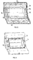
- FIGS. 8 and 9 where with the reference number 2a a section Door 2a shown in a corner area of a door, not otherwise shown Distribution cabinet is called.
- a hollow profile is closed all around at the door edge of door 2a 34 with a profile leg 23a and a semicircular peripheral section 33 educated.
- Fig. 1 to 6 Similar hollow profile all the way along the butt corners between the cabinet rear wall and the side walls are formed.
- the door 2a could undergo further deformations for stiffening including other e.g. have the frame parts connecting hollow profiles.
- FIG. 10 where a housing cover for a distributor housing is shown.
- these hollow profiles are also only a part Its circumference is formed by the front wall 2a and perpendicular side walls 60 and 61.
- the housing cover 1 is at 63 and 64 provided with stiffening ribs, which in cooperation with the hollow profiles for one great torsional rigidity of the housing cover.
- FIG. 11 shows a housing cover 1c of a distributor housing, in the case of a housing front wall 2c, offset from the edge of the front wall, stiffening the front wall Hollow profile 65 is formed in the form of a closed frame.
- FIG. 12 shows a distribution box cover 1d, which differs from only differentiates the housing cover 1 of the exemplary embodiment from FIGS. 1 to 7, that between the hollow profiles 18d and 19d running at the edge a cross over the front wall 2d of the housing cover 1d extending further hollow profile 40 is formed.
- the hollow profile 40 is also made in one piece with the housing cover trained according to the GID method.
Landscapes
- Engineering & Computer Science (AREA)
- Power Engineering (AREA)
- Casings For Electric Apparatus (AREA)
Abstract
Description
- Fig. 1
- einen gemäß einem ersten Ausführungsbeispiel für die vorliegende Erfindung ausgebildeten Gehäusedeckel eines Verteilergehäuses in einer Vorderansicht,
- Fig. 2
- den Gehäusedeckel von Fig. 1 in einer Schnittansicht gemäß Schnitt A2 - A2 von Fig. 1,
- Fig. 3
- den Gehäusedeckel von Fig. 1 in einer Rückansicht,
- Fig. 4
- den Gehäusedeckel von Fig. 1 in einer Seitenansicht gemäß Schnitt D - D von Fig. 3,
- Fig. 5
- ein Detail des Gehäusedeckels von Fig. 1 gemäß Schnitt G1 - G1 von Fig. 3,
- Fig. 6
- ein weiteres Detail des Gehäusedeckels von Fig. 1,
- Fig. 7
- ein weiteres Detail des Gehäusedeckels von Fig. 1 gemäß Schnitt K - K von Fig. 1,
- Fig. 8
- eine Teilansicht einer Verteilerschranktür gemäß einem zweiten Ausführungsbeispiel für die vorliegenden Erfindung,
- Fig. 9
- eine Teilschnittansicht der Tür von Fig. 8 gemäß Schnitt C - C,
- Fig. 10
- einen Gehäusedeckel für ein Verteilergehäuse gemäß einem dritten Ausführungsbeispiel für die vorliegende Erfindung,
- Fig. 11
- einen Gehäusedeckel für ein Verteilergehäuse gemäß einem vierten Ausführungsbeispiel für die vorliegende Erfindung, und
- Fig. 12
- ein Gehäusedeckel für ein Verteilergehäuse gemäß einem fünften Ausführungsbeispiel für die vorliegende Erfindung.
Claims (12)
- Gehäuse für Elektroinstallationseinrichtungen, insbesondere für Verteiler, Zählerplätze und dergleichen,
gekennzeichnet durch ein mit dem Gehäuse (2; 2a; 2b; 2c) verbundenes, das Gehäuse stabilisierendes Hohlprofil (18, 19; 34; 60; 65). - Gehäuse nach Anspruch 1,
dadurch gekennzeichnet, daß sich das Hohlprofil (18, 19; 34; 60; 65) wenigstens abschnittsweise entlang dem Rand einer Gehäusewand (2; 2a; 2b; 2c) erstreckt. - Gehäuse nach Anspruch 1 oder 2,
dadurch gekennzeichnet, daß das Hohlprofil (18, 19; 34; 60; 65) wenigstens abschnittsweise am Rand einer Gehäusewand (2; 2a; 2b) verläuft. - Gehäuse nach einem der Ansprüche 1 bis 3,
dadurch gekennzeichnet, daß das Hohlprofil (18, 19; 34; 65) an einer Gehäusewand (2; 2a; 2c) rahmenartig umlaufend ausgebildet ist. - Gehäuse nach Anspruch 4,
dadurch gekennzeichnet, daß das rahmenartig umlaufende Hohlprofil (18, 19) unterbrochen ist. - Gehäuse nach einem der Ansprüche 1 bis 5,
dadurch gekennzeichnet, daß das Hohlprofil (18, 19; 34; 60; 65) einstückig mit dem Gehäuse (2; 2a) ausgebildet ist. - Gehäuse nach einem der Ansprüche 1 bis 6,
dadurch gekennzeichnet, daß sich im Querschnitt gesehen das Hohlprofil (18, 19; 34; 60; 65) von dem Gehäuse (2; 2a) nach außen oder/und in den Gehäuseinnenraum hinein erstreckt. - Gehäuse nach einem der Ansprüche 1 bis 7,
dadurch gekennzeichnet, daß das Hohlprofil (18, 19; 34; 60; 65) über einen Teil seines Umfangs durch eine Gehäusewand (2; 2a; 2b; 2c) gebildet ist. - Gehäuse nach Anspruch 8,
dadurch gekennzeichnet, daß das Hohlprofil (18,19) im Eckenbereich winklig aneinandergrenzender Gehäusewände (2, 5 bis 8) durch die Gehäusewände (2, 5 bis 8) und einen die Gehäusewände verbindenden Umfangsabschnitt (25) gebildet ist. - Gehäuse nach Anspruch 9,
dadurch gekennzeichnet, daß der Umfangsabschnitt (25) unter Bildung eines dreieckigen Hohlprofils gerade oder entsprechend einer Kreislinie gebogen ist. - Gehäuse nach einem der Ansprüche 1 bis 10,
dadurch gekennzeichnet, daß das Hohlprofil (18, 19; 34;60; 65) durch Beaufschlagung des Werkstücks in einer Spritzgußform mit Gasinnendruck gebildet ist. - Gehäuse nach einem der Ansprüche 1 bis 11,
dadurch gekennzeichnet, daß sich das Hohlprofil (40) im Abstand vom Rand einer Gehäusewand (2d) entlang der Wandfläche erstreckt.
Applications Claiming Priority (2)
| Application Number | Priority Date | Filing Date | Title |
|---|---|---|---|
| DE20014371U DE20014371U1 (de) | 2000-08-11 | 2000-08-11 | Gehäuse für Elektroinstallationseinrichtungen |
| DE20014371U | 2000-08-11 |
Publications (2)
| Publication Number | Publication Date |
|---|---|
| EP1180837A1 true EP1180837A1 (de) | 2002-02-20 |
| EP1180837B1 EP1180837B1 (de) | 2008-10-01 |
Family
ID=7945403
Family Applications (1)
| Application Number | Title | Priority Date | Filing Date |
|---|---|---|---|
| EP01118078A Expired - Lifetime EP1180837B1 (de) | 2000-08-11 | 2001-07-26 | Gehäuse für Elektroinstallationseinrichtungen |
Country Status (2)
| Country | Link |
|---|---|
| EP (1) | EP1180837B1 (de) |
| DE (2) | DE20014371U1 (de) |
Citations (3)
| Publication number | Priority date | Publication date | Assignee | Title |
|---|---|---|---|---|
| CH554629A (de) * | 1972-07-03 | 1974-09-30 | Siemens Ag | Geraeteschrank zur aufnahme elektrischer geraete, insbesondere elektrischer installationsgeraete. |
| EP0008051A1 (de) * | 1978-08-03 | 1980-02-20 | BROWN, BOVERI & CIE Aktiengesellschaft Mannheim | Geräteabdeckung für schutzisolierte Verteilungseinsätze |
| FR2436516A1 (fr) * | 1978-09-18 | 1980-04-11 | Hager Electro | Perfectionnements aux supports pour tableaux d'abonne a l'electricite |
-
2000
- 2000-08-11 DE DE20014371U patent/DE20014371U1/de not_active Expired - Lifetime
-
2001
- 2001-07-26 EP EP01118078A patent/EP1180837B1/de not_active Expired - Lifetime
- 2001-07-26 DE DE50114358T patent/DE50114358D1/de not_active Expired - Lifetime
Patent Citations (3)
| Publication number | Priority date | Publication date | Assignee | Title |
|---|---|---|---|---|
| CH554629A (de) * | 1972-07-03 | 1974-09-30 | Siemens Ag | Geraeteschrank zur aufnahme elektrischer geraete, insbesondere elektrischer installationsgeraete. |
| EP0008051A1 (de) * | 1978-08-03 | 1980-02-20 | BROWN, BOVERI & CIE Aktiengesellschaft Mannheim | Geräteabdeckung für schutzisolierte Verteilungseinsätze |
| FR2436516A1 (fr) * | 1978-09-18 | 1980-04-11 | Hager Electro | Perfectionnements aux supports pour tableaux d'abonne a l'electricite |
Also Published As
| Publication number | Publication date |
|---|---|
| EP1180837B1 (de) | 2008-10-01 |
| DE50114358D1 (de) | 2008-11-13 |
| DE20014371U1 (de) | 2001-12-20 |
Similar Documents
| Publication | Publication Date | Title |
|---|---|---|
| DE19647814C2 (de) | Schaltschrank | |
| DE19647791C2 (de) | Eckverbindung für ein Rahmengestell | |
| EP0789944A1 (de) | Rahmengestell aus rahmenschenkeln und tiefenstreben | |
| DE69601007T2 (de) | Vorrichtung zur elastischen Befestigung eines Elektromotors in einem Gehäuse, insbesondere für Kraftfahrzeuge | |
| DE102016213286A1 (de) | Mehrteiliger Halterahmen, Konfektionier- und Bestückungsverfahren | |
| DE69610347T2 (de) | Winkelzubehörverbindungselement für Elektrokanal und Winkelzubehör dafür | |
| DE102015112563A1 (de) | Verbindungsanordnung zum Verbinden eines Pfostens an einem Rahmenprofil eines Fensters oder einer Türe aus Kunststoff | |
| DE2427427B2 (de) | Elektrische maschine mit einer mehrteiligen, koerperschallisolierten haube | |
| DE69300349T2 (de) | Schalldämpfende Lüftungsvorrichtung mit einem länglichen blockförmigen Gehäuse und einem spaltförmigen Lüftungskanal. | |
| EP1180837B1 (de) | Gehäuse für Elektroinstallationseinrichtungen | |
| DE2243329A1 (de) | Geraeuschdaemmendes, wandbildendes bauelement | |
| DE3506119A1 (de) | Kabelverzweigerschrank | |
| DE69607307T2 (de) | Abstandshaltermodul, insbesondere für modulare elektrische Geräte | |
| DE19620082C2 (de) | Kabelverzweigerschrank | |
| DE1276801B (de) | Kapselgehaeuse, insbesondere fuer elektrische Maschinen | |
| DE7525862U (de) | Grund bauteil für Boxen | |
| DE19726748C2 (de) | Kleingehäuse für den Wandanbau | |
| DE9204473U1 (de) | Gehäuse zum Einbau von elektrischen oder elektronischen Bauteilen bzw. Baugruppen | |
| EP1352456B1 (de) | Gehäuse, insbesondere für den einbau elektrischer und elektronischer bauteile | |
| DE69709602T2 (de) | Anschlussleiste | |
| DE2646602C2 (de) | Aufputzverteiler für die elektrische Hausinstallation | |
| DE29701537U1 (de) | Abdeckplatte für Haushaltsgeräte | |
| DE29706566U1 (de) | Schaltschrank für elektrische Anlagen | |
| DE69732338T2 (de) | Gehäusekörper mit integriertem Verankerungspunkt, insbesondere ein Unterteil für eine Zählertafel | |
| DE4101218A1 (de) | Beschlagteil |
Legal Events
| Date | Code | Title | Description |
|---|---|---|---|
| PUAI | Public reference made under article 153(3) epc to a published international application that has entered the european phase |
Free format text: ORIGINAL CODE: 0009012 |
|
| AK | Designated contracting states |
Kind code of ref document: A1 Designated state(s): AT BE CH CY DE DK ES FI FR GB GR IE IT LI LU MC NL PT SE TR |
|
| AX | Request for extension of the european patent |
Free format text: AL;LT;LV;MK;RO;SI |
|
| 17P | Request for examination filed |
Effective date: 20020622 |
|
| AKX | Designation fees paid |
Free format text: DE FR GB IT |
|
| 17Q | First examination report despatched |
Effective date: 20070627 |
|
| GRAP | Despatch of communication of intention to grant a patent |
Free format text: ORIGINAL CODE: EPIDOSNIGR1 |
|
| RAP1 | Party data changed (applicant data changed or rights of an application transferred) |
Owner name: HAGER ELECTRO GMBH & CO. KG |
|
| GRAS | Grant fee paid |
Free format text: ORIGINAL CODE: EPIDOSNIGR3 |
|
| GRAA | (expected) grant |
Free format text: ORIGINAL CODE: 0009210 |
|
| AK | Designated contracting states |
Kind code of ref document: B1 Designated state(s): DE FR GB IT |
|
| REG | Reference to a national code |
Ref country code: GB Ref legal event code: FG4D Free format text: NOT ENGLISH |
|
| REF | Corresponds to: |
Ref document number: 50114358 Country of ref document: DE Date of ref document: 20081113 Kind code of ref document: P |
|
| PLBE | No opposition filed within time limit |
Free format text: ORIGINAL CODE: 0009261 |
|
| STAA | Information on the status of an ep patent application or granted ep patent |
Free format text: STATUS: NO OPPOSITION FILED WITHIN TIME LIMIT |
|
| 26N | No opposition filed |
Effective date: 20090702 |
|
| GBPC | Gb: european patent ceased through non-payment of renewal fee |
Effective date: 20090726 |
|
| PG25 | Lapsed in a contracting state [announced via postgrant information from national office to epo] |
Ref country code: GB Free format text: LAPSE BECAUSE OF NON-PAYMENT OF DUE FEES Effective date: 20090726 |
|
| PGFP | Annual fee paid to national office [announced via postgrant information from national office to epo] |
Ref country code: IT Payment date: 20120724 Year of fee payment: 12 |
|
| REG | Reference to a national code |
Ref country code: DE Ref legal event code: R082 Ref document number: 50114358 Country of ref document: DE Representative=s name: PATENTANWAELTE BERNHARDT/WOLFF PARTNERSCHAFT, DE Ref country code: DE Ref legal event code: R082 Ref document number: 50114358 Country of ref document: DE Representative=s name: CABINET NUSS, FR |
|
| PG25 | Lapsed in a contracting state [announced via postgrant information from national office to epo] |
Ref country code: IT Free format text: LAPSE BECAUSE OF NON-PAYMENT OF DUE FEES Effective date: 20130726 |
|
| REG | Reference to a national code |
Ref country code: DE Ref legal event code: R082 Ref document number: 50114358 Country of ref document: DE Representative=s name: CABINET NUSS, FR |
|
| REG | Reference to a national code |
Ref country code: FR Ref legal event code: PLFP Year of fee payment: 16 |
|
| REG | Reference to a national code |
Ref country code: FR Ref legal event code: PLFP Year of fee payment: 17 |
|
| REG | Reference to a national code |
Ref country code: FR Ref legal event code: PLFP Year of fee payment: 18 |
|
| PGFP | Annual fee paid to national office [announced via postgrant information from national office to epo] |
Ref country code: DE Payment date: 20180727 Year of fee payment: 18 Ref country code: FR Payment date: 20180726 Year of fee payment: 18 |
|
| REG | Reference to a national code |
Ref country code: DE Ref legal event code: R119 Ref document number: 50114358 Country of ref document: DE |
|
| PG25 | Lapsed in a contracting state [announced via postgrant information from national office to epo] |
Ref country code: DE Free format text: LAPSE BECAUSE OF NON-PAYMENT OF DUE FEES Effective date: 20200201 |
|
| PG25 | Lapsed in a contracting state [announced via postgrant information from national office to epo] |
Ref country code: FR Free format text: LAPSE BECAUSE OF NON-PAYMENT OF DUE FEES Effective date: 20190731 |