EP1180784A2 - Method and apparatus for charged particle beam exposure - Google Patents
Method and apparatus for charged particle beam exposure Download PDFInfo
- Publication number
- EP1180784A2 EP1180784A2 EP01119151A EP01119151A EP1180784A2 EP 1180784 A2 EP1180784 A2 EP 1180784A2 EP 01119151 A EP01119151 A EP 01119151A EP 01119151 A EP01119151 A EP 01119151A EP 1180784 A2 EP1180784 A2 EP 1180784A2
- Authority
- EP
- European Patent Office
- Prior art keywords
- charged particle
- data
- exposure
- particle beam
- particle beams
- Prior art date
- Legal status (The legal status is an assumption and is not a legal conclusion. Google has not performed a legal analysis and makes no representation as to the accuracy of the status listed.)
- Granted
Links
Images






Classifications
-
- H—ELECTRICITY
- H01—ELECTRIC ELEMENTS
- H01J—ELECTRIC DISCHARGE TUBES OR DISCHARGE LAMPS
- H01J37/00—Discharge tubes with provision for introducing objects or material to be exposed to the discharge, e.g. for the purpose of examination or processing thereof
- H01J37/30—Electron-beam or ion-beam tubes for localised treatment of objects
- H01J37/302—Controlling tubes by external information, e.g. program control
- H01J37/3023—Program control
- H01J37/3026—Patterning strategy
-
- H—ELECTRICITY
- H01—ELECTRIC ELEMENTS
- H01J—ELECTRIC DISCHARGE TUBES OR DISCHARGE LAMPS
- H01J2237/00—Discharge tubes exposing object to beam, e.g. for analysis treatment, etching, imaging
- H01J2237/30—Electron or ion beam tubes for processing objects
- H01J2237/317—Processing objects on a microscale
- H01J2237/3175—Lithography
- H01J2237/31774—Multi-beam
Definitions
- the present invention relates to a method and an apparatus for charged particle beam exposure that control charged particle beams and exposes a pattern of LSI and the like on a sample, more particularly to a method and an apparatus for charged particle beam exposure that use a plurality of charged particle beams.
- a multibeam exposure system using a plurality of the charged particle beams has been proposed for improving the processing capability (throughput) of the apparatus.
- a blanking aperture array system is cited (H. Yasuda, J. VAC. Dci. Technol., B14 (6), 1996).
- a blanking aperture array formed of a plurality of aperture groups is used, which has a blanking electrode capable of independent control of an applied voltage.
- An electron beam from a single electron source is divided into a plurality of electron beams, and turning on/off of each electron beam is controlled by the blanking electrode capable of independent control.
- a beam shape formed by the group of the electron beams that consist of a plurality of the electron beams can be arbitrarily set. Accordingly, the throughput of the apparatus is improved because the electron beam of any shape can be obtained.
- the dimension of the electron beam divided by the blanking aperture array is as large as approximately 100nm on the sample, and the system is the one that divides the single charged particle beam.
- the number of charged particle beams obtained has been limited to several hundred to one thousand, which has caused limitation to a dimension control of a pattern to be exposed and insufficient resolving power.
- error occurs in the exposure of proximate portions due to exposure dose distribution generated by scattering of the electrons in resist, reflected electrons from a sample surface or the like.
- a special processing process has been required for a proximate effect correction for correcting the error. Such problems are apt to be more apparent as the exposure pattern becomes finer.
- the apertures in a shifted relation are selected from each column in plural numbers in accordance with the dimension of the pattern to be exposed. Then, each of the electron beams generated from the apertures is irradiated in a superposing manner to control exposure dose at the end portion of the pattern.
- a high processing accuracy is required for processing the apertures in a positional accuracy between the apertures.
- a higher processing accuracy and an increase of the number of apertures are required in order to make a dimension control resolving power finer by improving the resolving power of a shift amount.
- a control circuit of the blanking aperture array becomes complex because selection of the apertures for exposing the end portion of the pattern is necessary depending on the pattern dimension.
- the proximity effect correction is the one, as disclosed in Japanese Patent Laid-Open No. Hei5(1993)-175018 gazette, No. Hei5(1993)-206016 gazette and No. Hei6(1994)-53129 gazette, in which a correction exposure process is performed for correcting an exposure dose error by a proximity effect occurred in an exposure process in addition to an actual pattern exposure process.
- reduction of the throughput is inevitable because the number of exposure processes is increased.
- a method that does not require the correction exposure process there exists a system as disclosed in Japanese Patent Laid-Open No. Hei9(1997)-63926 that data in which exposure data for correcting the exposure error by pattern data is added to the pattern data is formed prior to exposure and a corrected pattern is obtained by one exposure process. In this system, a long time is consumed since conditions need to be obtained by generation of the pattern data and a test writing, which leads to reduction of a total throughput of the apparatus.
- a charged particle beam exposure method and a charged particle beam exposure apparatus described in each claim are adopted to solve the problems in the above-described conventional art.
- a beam source may be either plural or single.
- the charged particle beam exposure apparatus that exposes an LSI pattern or the like by irradiating a group of the charged particle beams formed by a plurality of the charged particle beams on a sample
- the charged particle beams that constitute a plurality of the charged particle beam groups is irradiated in a superposing manner to a specified section of a specified pattern (a charged particle beam section) to obtain a predetermined exposure intensity.
- a desired charge quantity is irradiated on a desired point on the sample, and a desired exposure dimension is obtained.
- a plurality of the charged particle beams are used, of which current quantities are made to have a weighted gradation, the desired charge quantity is irradiated, and thus the desired exposure dimension is obtained.
- a map for a number of shots determined by the dimension resolving power in a mesh and an exposure dose map based on introduction of an existence density concept of the pattern across a plurality of meshes are formed, and data of the maps is given to the charged particle beams side as data. Accordingly, the charged particle beams are allowed to have a high gradation capable of the exposure dose correction necessary for the proximate effect correction.
- the number of gradations can be set by finely controlling an irradiated charge quantity of the charged particle beams and high dimension controllability is obtained.
- the number of beams forming the charged particle beam group can be considerably reduced and the beam source and a control apparatus can be simplified. Additionally, since the data for irradiation is corrected regarding the proximate effect correction, the throughput is improved because a special process is not required.
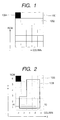
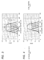
- Figs. 1 and 2 are views for explaining a method of a writing processing according to the embodiments of the present invention.
- a group of a plurality of charged particle beams forms a matrix 1001 of charged particle beams, in which the charged particle beams 1002 are arranged in a matrix defined by rows and columns perpendicular to each other as shown in Fig. 1.
- a writing region is divided in a mesh state defined by rows and columns perpendicular to each other as shown in Fig. 2.
- Dimensions of mesh 1003 equals to dimensions of one charged particle beam source 1004, which constitutes the matrix 1001 of charged particle beams, when reduced and projected on a sample.
- the dimensions of the mesh 1003 is set larger than a dimension resolving power of an exposure pattern 1005. Therefore, dimensions of the exposure pattern are not necessarily equal to a multiple of the dimensions of the mesh 1003.
- Fig. 3 shows an axis of abscissas showing an exposure position (unit: nm) and an axis of ordinates shows an exposure dose (optional unit).
- Fig. 3 shows an exposure dose 2001 of a single charged particle beam and a total exposure dose 2002 obtained as a result thereof supposing that the irradiation dose by each beam constituting the matrix of the charged particle beams has the Gaussian distribution.
- the total exposure dose 2002 finally obtained is an integral value of the irradiation dose given by each beam.
- An exposure pattern size 2003 is determined by a region of the total exposure dose 2002 that exceeds a sensitivity threshold value 2004 of a photosensitive material.
- the total exposure dose 2002 has been controlled to obtain desired dimensions by allowing the beam including the exposure dose of the Gaussian distribution in Fig. 3 to be positioned and irradiated in an unit equal to a desired dimension resolving power or finer.
- the beam including the exposure doze 2001 of the Gaussian distribution is used, a plurality of the beams are arranged in a matrix, and a beam intensity at an end portion is controlled.
- the pattern size can be optionally selected.
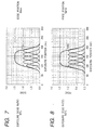
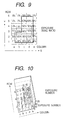
- Total exposure dose 3001, 3002, 3003, 3004 and 3005 in Figs. 4 to 8 shows the exposure dose of the position of a line X1-X2 in Fig. 2, and each Gaussian distribution shows the exposure dose of the columns "a" to "e” of a first row of the mesh. Moreover, a size of each beam and a pitch of the mesh are set at 20nm.
- Each graph shows the exposure dose of a single charged particle beam and the total exposure dose when the exposure dose of the "a" column of the first row is varied from 10% to 100%.
- the sensitivity threshold value of the photosensitive material is made to be 1.0 on the axis of ordinates in the graph, a pattern edge position in each state is shown by a position of circle in each of Figs.
- the exposure dose of each beam is varied in accordance with the desired dimensions.
- a desired pattern dimension control is enabled by the beam having a larger size or arranged in a larger distance than the pattern dimension resolving power.
- a ratio of the dimensions (area) of a pattern included in each mesh to the mesh dimensions (area) is used as an index as shown in Figs. 9 and 10, and the exposure dose to each mesh is varied depending on the ratio data.
- a percentage of the dimensions (area) of the pattern in the mesh dimensions (area) is decided to determine the minimum unit.
- a series of this operation is a gradation process.
- the exposure dose to each mesh is not controlled by varying a current quantity or an exposure time of the beam for exposure.
- the exposure dose is varied in a method that a deflection control of the matrix of charged particle beams is performed in a column direction on the sample, the same mesh is subjected to a superposing exposure by different beams in the same column, and the number of superposing exposure to each mesh is controlled by the dimension ratio data. Accordingly, the exposure dose to each mesh can be controlled by the number of superposing exposures, and the desired exposure dose can be obtained for every mesh. For example, in the case where one hundred beams having the same current quantity are arrayed in a column direction, the exposure dose of 1% is controlled if any one of these beams is turned on. In the case of the ratio of 33%, thirty-three beams are turned on, and are used to the superposing exposure (the exposure is performed by thirty-three times to the same mesh). Thus, the desired exposure dose is obtained.
- Fig. 11 shows the exposure dose of each mesh depending on the ratio data.
- a mesh (2, a) has the exposure dose of 33%, which implies that the superposing exposure is performed by thirty-three times when it is shown by the number of shots of the charged particle beams that are not weighted.
- description will be made regarding the columns from “a” to "e” of the first row.
- a matrix 5001 of charged particle beams has a constitution of one hundred rows and five columns (a, b, c, d, e), and all the beams have the equal current quantities.
- a beam (shown by (1, a)) irradiated on the mesh of "a" column of the first row is represented as a gradation number of eleven.
- the beams from the first row to the eleventh row in the "a" column of the matrix 5001of charged particle beams are deflected with a deflection unit and sequentially irradiated on the same position corresponding to the mesh (1, a) of the sample in a superposing manner.
- the beam irradiated on a mesh (1, b) has the number of superposing exposures of sixty-six, that is, the gradation number of sixty six having one hundred as the maximum number.
- the beams from the first row to the sixty-sixth row in the "b" column of the matrix 5001 of charged particle beams are deflected with the deflection unit and sequentially irradiated on the same position of the sample in a superposing manner. Since the beam irradiated on a mesh (1, c) has the gradation number of sixty six, the beams from the first row to the sixty-sixth row in the "c" column of the matrix 5001 of charged particle beams are deflected with the deflection unit and sequentially irradiated on the same position of the sample in a superposing manner.
- the beams from the first row to the sixty-sixth row in the "d" column of the matrix 5001 of charged particle beams are deflected with the deflection unit and sequentially irradiated on the same position corresponding to the mesh (1, d) of the sample in a superposing manner. Since the beam irradiated on a mesh (1, e) in Fig.
- the beams from the first row to the twenty-second row in the "e" column of the matrix 5001 of charged particle beams are deflected with the deflection unit and sequentially irradiated on the same position of the sample in a superposing manner.
- Fig. 13 is a result that the exposure dose is converted to the gradation number of each mesh depending on the ratio data, which explains a specific exposure method in accordance with the result.
- description will be made also for the meshes of the columns from "a" to "e” of the first row.
- a matrix 6001 of charged particle beams has a constitution of eight rows and five columns (a, b, c, d, e), and a weight of the beam current quantity is set at a power of 2 for each row. Therefore, the maximum gradation number of two hundred and fifty six is possible in this system. Since the beam irradiated on a mesh (1, a) in Fig.
- the charged particle beams where the current quantities are weighted are used, and the number of beams constituting the matrix of charged particle beams can be significantly reduced in comparison to the charged particle beams having a single current quantity.
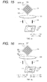
- Figs. 15 to 18 Each charged particle beam emitted from a matrix of charged particle beams 101 is reduced by a lens 103 by an optional value, positioned by a deflection unit 104, and irradiated on a sample 106 mounted on a sample stage 105.
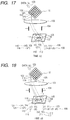
- Fig. 15, Fig. 16, Fig. 17 and Fig. 18 show states of an exposure operation arranged in a time series. Description will be made only for four charged particle beams (122, 123, 124 and 125) in the matrix 101 of charged particle beams. Firstly, in a state of Fig. 15, ratio data (a) 126 is given to the matrix 101 of charged particle beams.
- the data (a) shows the number of superposing exposures to a mesh 107, and four times are specified in this case.
- the charged particle beam 122 goes through a route 102 to reach the mesh 107 on the sample 106.
- Coordinates 108 of the mesh 107 on the sample are (x1, y1), and a charge quantity 109 irradiated is J1.
- Ratio data (b) 127 is given to the matrix 101 of charged particle beams.
- the data (b) shows the number of superposing exposures to a mesh 111, where one time is specified.
- Each charged particle beam is deflected by the deflection unit 104 more to the left side on the drawing in comparison to the state of Fig. 15. Accordingly, the charged particle beam 122 goes through the route 102 to reach the mesh 111 on the sample 106. Coordinates 112 of the mesh 111 on the sample at this time are (x2, y2), and a charge quantity 113 irradiated is J1.
- the charged particle beam 123 goes through a route 110 to reach the mesh 107 on the sample 106.
- the coordinates 108 of the mesh 107 on the sample at this time are (x1, y1), which coincides with a point irradiated by the charged particle beam 122 at the state of Fig. 15. Therefore, the second exposure is performed on the mesh 107, and the charge quantity 109 becomes J1 + J2.
- Ratio data (c) 128 is given to the matrix 101 of charged particle beams.
- the data (c) shows the number of superposing exposures to a mesh 117, where two times is specified.
- Each charged particle beam is deflected by the deflection unit 104 more to the left side on the drawing in comparison to the state of Fig. 16. Accordingly, the charged particle beam 122 goes through the route 102 to reach the mesh 117 on the sample 106.
- Coordinates 115 of the mesh 117 on the sample at this time are (x3, y3), and a charge quantity 116 irradiated is J1.
- the charged particle beam 124 goes through a route 114 to reach the mesh 107 on the sample 106.
- Coordinates 108 of the mesh 107 on the sample at this time are (x1, y1), which coincides with the point irradiated by the charged particle beam 122 at the state of Fig. 15 and a point irradiated by the charged particle beam 123 at the state of Fig. 16. Therefore, the third exposure is performed on the mesh 107, and the charge quantity 109 becomes J1 + J2 + J3. As to the mesh 111, since the number of superposing exposures of one time is specified, no exposure is performed. Accordingly, the charged particle beam 123 is not generated.
- Ratio data (d) 129 is given to the matrix 101 of charged particle beams.
- the data (d) shows the number of superposing exposures to a mesh 118, where one time is specified.
- Each charged particle beam is deflected by the deflection unit 104 more to the left side on the drawing in comparison to the state of Fig. 17. Accordingly, the charged particle beam 122 goes through the route 102 to reach the mesh 118 on the sample 106.
- Coordinates 120 of the mesh 118 on the sample at this time are (x4, y4), and a charge quantity 121 irradiated is J1.
- the charged particle beam 123 goes through a route 110 to reach the mesh 117 on the sample 106.
- the coordinates 115 of the mesh 117 on the sample at this time are (x3, y3), which coincides with the point irradiated by the charged particle beam 122 having an area at the state of Fig. 17. Therefore, the second exposure is performed on the mesh 117, and the charge quantity 116 becomes J1 + J2.
- the charged particle beam 125 goes through a route 119 to reach the mesh 107 on the sample 106.
- the coordinates 108 of the mesh 107 on the sample at this time are (x1, y1), which coincides with the point irradiated by the charged particle beam 122 at the state of Fig. 15, the point irradiated by the charged particle beam 123 at the state of Fig.
- the fourth exposure is performed on the mesh 107, and the charge quantity 109 becomes J1 + J2 + J3 + J4. Since the specified number of superposing exposures of one time is completed to the mesh 111 at the state of Fig. 16, the charged particle beam 124 is not generated.
- the superposing exposure is completed: four times to the mesh 107; one time to the mesh 111; two times to the mesh 117; and one time to the mesh 118.
- the number of charged particle beams can be reduced when the matrix 6001 of charged particle beams as shown in Fig. 14 is used, where the current is weighted to the charged particle beams, instead of the matrix 5001 of charged particle beams that are equal to each other as shown in Fig. 12.
- Generation and non-generation of each of a plurality of the charged particle beams that constitute the matrix of charged particle beams are controlled, a group of the charged particle beams generated is controlled and deflected, and then the different charged particle beams constituting the group of the charged particle beams are irradiated on the same point of the sample in a superposing manner.
- a desired charge quantity can be irradiated on a desired mesh on the sample, and it is also possible to allow the exposure dose of every mesh to have the gradation. Accordingly, the dimensions can be controlled.
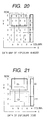
- Fig. 20 is a number data map of exposure, where the dimension resolving power is considered.
- Fig. 21 is an exposure dose data map, where the proximate effect across a plurality of meshes is considered.
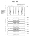
- a sub matrix of charged particle beams are provided by the maximum number of the number data of exposure relative to the matrix of charged particle beams explained in Fig. 14.
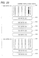
- Sub matrixes of charged particle beams (8001, 8002, 8003, 8004, 8005, 8006, 8007, 8008, 8009) in Fig. 19, Fig. 22 and Fig. 23 show such sub matrix.
- the pattern shown in Fig. 20 is a result where the exposure dose is converted to the gradation number of each mesh in accordance with the ratio data.
- the maximum value of the gradation number was set at nine.
- exposure dose data defined across a plurality of meshes are obtained.
- an existence density of the pattern which is determined depending on how many patterns exist in the region across a plurality of the meshes, is calculated in every region across a plurality of meshes.
- An irradiation current quantity is controlled to be constant such that the exposure dose is reduced in the case of a high pattern existence density and increased in the case of a low pattern existence density at every region unit across a plurality of meshes.
- a map is formed in which the exposure dose is calculated depending on the pattern existence density for every region, which is allocated across a plurality of meshes as shown by dotted lines in Fig. 21.
- the charge quantity to be irradiated on the pattern is increased.
- the charge quantity is reduced.
- Such a correction is performed to make sensitivity of the photosensitivity material to the charge quantity to be averaged, and thus dimension accuracy is obtained.
- both the dimension control by the number of shots in accordance with the pattern dimensions shown in Fig. 20 and a micro exposure control by the exposure dose across a plurality of meshes must be performed to execute writing by taking the highly accurate dimension controllability and the proximate effect correction in consideration.
- both of the dimension control and the micro exposure control must be performed simultaneously.
- an exposure system is adopted that the exposure dose data as the data for the micro exposure control and the number data for exposure as the data for the dimension control are separately transferred to a plurality of the sub matrixes to control the charged particle beam source.
- FIG. 19 shows the sub matrixes in the case where the maximum value of nine of the number data is transferred, the number data being the data for controlling the dimension control.
- the drawing shows that the charged particle beams of the sub matrix are weighted in the column direction by 2 0 to 2 7 and arrayed, a part of which is omitted (similarly, in Figs. 22 and 23). Both the dimension control and the micro exposure control can be simultaneously performed in the constitution of the sub matrix of charged particle beams. Description will be made with reference to Figs. 22 and 23.
- Fig. 22 shows the case where the fifth row of the number data map for irradiating the charged particle beams shown in Fig. 20 is exposed. Comparing with the number data map, in Fig. 21 as the exposure dose data map in which the proximate effect is considered across a plurality of meshes, the value in the same position (5, a) shows 65.
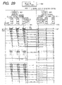
- Fig. 29 will describe a procedure for driving the charged particle beam source in the sub matrix shown in Fig. 19 to irradiate the charged particle beam on the sample depending on the value of the map.
- the maximum value on the number data map is set at nine.
- a mesh (5, a) has the number of exposure (gradation number) of four times and the exposure dose of 65. In other words, the number of sub matrixes is nine.
- Fig. 29 shows a circuit constitution connecting to three of these.
- the value of the number data map and the value of the exposure dose data map are stored. Supposing a time T1 is a starting point, the exposure dose data is delayed in a first shift register by a delayed amount corresponding to a binary weight. At a time T2, data of the exposure dose data map (6, a) is inputted to the first shift register. In this manner, data is read out sequentially from storage sections (14005 to 14007) to be inputted to the first shift register up to a time T8.
- the data inputted to the first shift register at the time T1 is inputted to a second shift register, and the value of the exposure data map (14, a) is simultaneously inputted to the first shift register.
- the data inputted to the first shift register at the time T1 is inputted to a third shift register.
- the second, third and fourth shift registers have the same operation as the first shift register even at the different times.
- the amount specified in the number data map determines the number of same operation.
- the number data is sent from storage sections (14008 to 14010). For example, when the number data sent is four times, the data goes through a converter (14012) that converts a binary number to an unary number such that four pieces of "1" are outputted, and the data is inputted to a first shift register (14017) that delays the data.
- the least significant bit of the "a" column of the first shift register (14017) controls output of the "a” column of the first resister.
- the second bit of the "a” column controls output of the "a” column of the second shift register in the same manner.
- the least significant bit of the "b" column of the first shift register (14017) controls output of the "b” column of the first resister.
- the second bit of the "b” column controls output of the second shift register of the "b” column in the same manner. For example, if the data inputted to the first shift register (14017) at the time of T1 is: four [1111] for the "a" column; nine [111111111] for the "b” column; nine [111111111] for the "c” column; six [111111] for the "d” column; and six [111111] for the "e” column, a map (5, a) of Figs.
- a number data map (5, b) is exposed with the exposure dose of 65 by superposing for nine times. Accordingly, a mesh (5, b) is sequentially exposed by nine sub matrixes 8001 to 8009 of charged particle beams with the exposure dose of 65 in a superposing manner.
- a number data map (5, c) has the gradation number of nine and a coefficient of the micro exposure correction of 65.
- a mesh (5, c) is sequentially exposed by the nine sub matrixes 8001 to 8009 of charge particle beams with the exposure dose of 65 in a superposing manner.
- a number data map (5, d) is sequentially exposed by the sub matrixes 8001 to 8006 of charge particle beams with the exposure dose of 65 in a superposing manner. Accordingly, a mesh (5, e) is sequentially exposed by the sub matrixes 8001 to 8006 of charged particle beams with the exposure dose of 83 in a superposing manner.
- Fig. 23 shows the case where the first row of the pattern shown in Fig. 20 is exposed.
- Number data maps (1, a) to (1, d) are not exposed because the number data is 0.
- a number data map (1, e) has the number data of 6 and the exposure dose data of 122. Accordingly, the number data map (1, e) is sequentially exposed by the six sub matrixes 8001 to 8006 of charged particle beams with the exposure dose of 122 in a superposing manner.
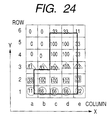
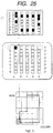
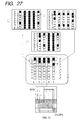
- Figs. 24 to 27 are views showing how the data and exposure are processed on a time series by taking the matrix of charged particle beams having the constitution described in Figs. 13 and 14.
- This system is the one in which the exposure dose for the pattern to be exposed on the sample is divided in a mesh unit, the exposure dose data for every mesh is converted into a binary number of N bits to be stored, and then, the N bits of the binary number are shifted for N times by a control clock depending on the weight. Thus, the matrix of charged particle beams having N rows is driven.
- the exposure data of each mesh corresponding to a portion of the first row of the mesh is converted into a binary number at a time T1.
- the least significant bit is transferred to (1, a) of the matrix of charged particle beams without shifting, and the (1, a) on the mesh is irradiated.
- the second bit after delayed by one clock by the control clock, that is, after the time T2, is transferred to (2, a) of the matrix of charged particle beams, and the (1,a) on the mesh is irradiated.
- the third bit after delayed by two clocks by the control clock, that is, after the time T3, is transferred to (3, a) of the matrix of charged particle beams, and the (1, a) on the mesh is irradiated.
- the least significant bit is transferred to (1, b) of the matrix of charged particle beams without shifting similarly to the "a" column, and the (1, b) on the mesh is irradiated.
- the second bit after delayed by one clock by the control clock, that is, after the time T2, is transferred to (2, b) of the matrix of charged particle beams, and the (1, b) on the mesh is irradiated.
- the third bit after delayed by two clocks by the control clock, that is, after the time T3, is transferred to (3, b) of the matrix of charged particle beams, and the (1, b) on the mesh is irradiated.
- the exposure dose of the second row is taken out from the storage section, and the least significant bit is transferred to (1, a) of the matrix of charged particle beams without shifting, and the (2, a) on the mesh is irradiated.
- the third bit after delayed by two clocks by the control clock, that is, after the time T4, is transferred to (3, a) of the matrix of charged particle beams, and the (2, a) on the mesh is irradiated.
- the system is the one in which the meshes are allocated to all the patterns on the sample in advance, the exposure dose to each mesh is determined, and the exposure is completed by utilizing a time delay.
- the data of the first row marked with a circle in the drawing is given. This data is converted into a binary number. Among the data, the data of a bit having the weight of the zero power of 2 is given to the first row of each column of the matrix of charged particle beams. Since the time T1 is the exposure starting time, 0 is set to the other rows. In the case of this example, only (1, a) of the matrix of charged particle beams is turned on at the time T1. The beam is irradiated on (1, a) of the mesh on the sample.
- the data of the second row marked with a square mark in the drawing is given in addition to the foregoing data.
- This data is also converted into a binary number.
- the data of a bit having the weight of the first power of 2 of the data with the circle mark is given to the second row of each column of the matrix of charged particle beams.
- the data having the weight of the zero power of 2 of the data with the square mark is given to the first row of each column of the matrix of charged particle beams. 0 is set to the other rows.
- all of the first and second rows of each column of the matrix of charged particle beams are turned on at the time of T2.
- the beam of the first row is irradiated on the second row of the mesh on the sample.
- the beam of the second row is irradiated on the first row of the mesh on the sample.
- the data of the third row marked with a triangle mark in the drawing is given in addition to the foregoing data.
- This data is also converted into a binary number.
- the data of a bit having the weight of the second power of 2 of the data with the circle mark is given to the third row of each column of the matrix of charged particle beams.
- the data having the weight of the first power of 2 of the data with the square mark is given to the second row of each column of the matrix of charged particle beams.
- the data having the weight of the zero power of 2 of the data with the triangle mark is given to the first row of each column of the matrix of charged particle beams. 0 is set to the other rows.
- all the columns of the first row, "b", “c” and “d” columns of the second row and (3, e) of the matrix of charged particle beams are turned on at the time T3.
- the beam of the first row is irradiated on the third row of the mesh on the sample
- the beam of the second row is irradiated on the second row of the mesh on the sample
- the beam of the third row is irradiated on the first row of the mesh on the sample.
- Fig. 28 is the view showing the constitution of the control system that controls the matrix of charged particle beams in Fig. 14 (1 to 8, a to e) having the constitution described in Figs. 13 and 14.
- the matrix of charged particle beams is in the constitution of eight rows and five columns.
- Each shot data is stored in table memories (13004 to 13008) of shot data provided for each column in advance.
- a timing for reading out the shot data from the table memories of shot data is determined by a control clock 13002 of deflection control circuit.
- An address is determined by counting the control clock 13002 of deflection control circuit with an address counter 13003.
- the data read out is converted into a binary number of 8 bits.
- the constitution is made such that the converted data is taken into a shift register 13010 provided for every bit by synchronizing with the control clock 13002 of deflection control circuit.
- the constitution is also made such that deflection of the deflection unit is performed for every mesh unit on the sample at every counting of the clock C1.
- the control clock C2 of deflection control circuit is generated. Accordingly, an address AD2 is determined, and data DT2 stored in the AD2 is read out, converted into a binary number, and sent to the shift register. Each shift register transfers each data to a next shift register connected thereto and takes in data that has been sent.
- the data of the bit having the weight of the zero power of 2 of the shot data DT2 is given to the beams constituting the matrix of charged particle beams. Thus, on/off of the beams are controlled.
- the data having the weight of the first power of 2 of the shot data DT1 is given to the beams constituting the matrix of charged particle beams. Thus, on/off of the beams are controlled.
- the control clock C3 of deflection control circuit is generated. Accordingly, an address AD3 is determined, and data DT3 stored in the AD3 is read out, converted into a binary number, and sent to the shift register. Each shift register transfers each data to a next shift register connected thereto and takes in data that has been sent.
- the data of the bit having the weight of the zero power of 2 of the shot data DT3 is given to the beams constituting the matrix of charged particle beams. Thus, on/off of the beams are controlled.
- the data of the bit having the weight of the 1st power of 2 of the shot data DT2 is given to the beams constituting the matrix of charged particle beams. Thus, on/off of the beams are controlled.
- the data of the bit having the weight of the second power of 2 of the shot data DT1 is given to the beams constituting the matrix of charged particle beams. Thus, on/off of the beams are controlled.
- the above operations are repeated.
- Fig. 29 is a constitution example of a control system when the matrix of charged particle beams has a sub matrix constitution.
- the number of the sub matrixes is determined by deciding the minimum dimension resolving power for an area (dimensions) of the charged particle beam source 1004 shown in Fig. 1. For example, in Fig. 29, when the dimension of an electron source is 18nm and the minimum dimension resolving power is set at 6nm, the number of the sub matrixes becomes three. In other words, pattern of 6nm is written per one shot.
- Each sub matrix in Fig. 29 has a constitution of eight rows and three columns. In this case, there are two kinds of data for controlling the matrix of charged particle beams.
- one is shot number data associated with the dimension control
- the other is micro exposure dose data for averaging the proximate effect across a plurality of meshes, that is, the exposure dose.
- the micro exposure dose data is stored in table memories (1) (14005, 14006, 14007) of shot data.
- the shot number data associated with the dimension control is stored in table memories (2) (14008, 14009, 14010) of shot data.
- an address of each table memory of shot data the one is used in which a control clock 14002 of deflection control circuit synchronized with the operation of a deflection control system 14001 is counted with address counters 14003 and 14004.
- Reference numerals 14013, 14016 and 14017 denote shift registers.
- a charged particle beam source 14015 (which corresponds to (1, a) of Fig. 14), that constitutes the matrix of charged particle beams is controlled to turn on/off depending on the data from the shift registers.
- the shot number data goes from the table memories (2) (14008, 14009, 14010) of shot data through a unary coded decimal converter (14012), and the beams connected to the shift registers are controlled to turn on/off.
- a unary coded decimal converter 14012
- the shot number is set at two times, two ones are set at the output of the decimal-to-binary converter, which causes sub matrixes 1 and 2 of charged particle beams to be in an operation state and a sub matrix 3 of charged particle beams to be in an non operation state.
- the number of superposing by the minimum dimension resolving power and a corrected exposure dose per one shot are multiplied for exposure.
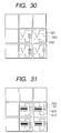
- Figs. 30 and 31 are views explaining the method for allowing each electron beam to have a different current quantity in the case where the matrix of charged particle beams is constituted of an electron source such as a field emission type electron source and an MIM electron source.
- a current value can be controlled by a bias state given thereto.
- a power source 1503 connected between an electron source chip 1501 and a leading electrode 1502 shown in Fig. 30 is varied.
- a power source 1601 connected between electrodes 1602 and 1603 that sandwich an insulation film 1601 is varied.
- the bias state is independently set for every electron source as in this embodiment. Therefore, the matrix of charged particle beams can have any mode among the cases where irradiation charge quantities of all charged particle beams are equal, different or weighted at a certain ratio.
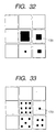
- Figs. 32 and 33 are views explaining the method for allowing each electron beam to have a different current quantity in the case where the matrix of charged particle beams is constituted of an electron source such as the MIM electron source.
- the current value can be controlled by controlling an area of an electron emission portion 1701.
- Fig. 32 shows the case where the current quantity is controlled by varying an electron emission area, and the current quantity is determined by forming the emission area large or small.
- Fig. 33 shows the case where the current quantity is controlled by the integration number of the electron emission portions having a certain size, which has the same effect as the case of Fig. 32.
- the electron emission area is independently set for every electron source as in this embodiment. Therefore, the matrix of charged particle beams can have any mode among the cases where irradiation charge quantities of all charged particle beams are equal, different or weighted at a certain ratio.
- the present invention is characterized in that writing is performed in dimensions smaller than the size of the surface electron source.
- the present invention provides a circuit constitution in which the beam current quantity of the surface electron source is controlled and the dimension accuracy equal to the size of the surface electron source or less is realized.
- the circuit constitution is suitable for an IC circuit combined with the surface electron source.
- writing of a plurality of circuit patterns on the sample can be performed freely and flexibly without using a mask. Even if the mesh allocated on the sample has large dimensions, the gradation number can be set by finely controlling the irradiation charge quantity of the charged particle beams. Accordingly, a high resolving power can be obtained in the control resolving power of the pattern dimensions.
- This system solves the problems of an enormous number of surface electron sources and a transfer rate in a data transfer, which occur in a system of transferring data by arranging the surface electron sources corresponding one by one to the sample pattern.
- the system also can be integrally constituted with the surface electron sources in a circuit suitable for an IC.
- the number of beams constituting the matrix of charged particle beams can be reduced significantly (the number of charged particle beam sources can be reduced), simplification of the matrix beam control circuit, reduction of a packaging size and the like are enabled.
- the number data map for irradiating the charged particle beams and the exposure dose data map in which the proximate effect across a plurality of meshes is considered can be formed in a high speed.
- the system has a constitution in which the number data map and the exposure dose data map are simultaneously controlled, and thus the throughput of the exposure is improved.
Landscapes
- Chemical & Material Sciences (AREA)
- Analytical Chemistry (AREA)
- Electron Beam Exposure (AREA)
- Exposure And Positioning Against Photoresist Photosensitive Materials (AREA)
Abstract
Description
Claims (13)
- A method for charged particle beam exposure using a plurality of charged particle beams to be irradiated on a sample and using exposure data for exposing a predetermined pattern on a sample, the charged particle beams being arranged in a matrix consisting of a row component and a column component and having different current quantities in a column direction, said method comprising the steps of:generating control data by converting said exposure data into data for setting the number of turning on/off of a plurality of said charged particle beams arranged in said matrix in accordance with a line width of the predetermined pattern to control a plurality of said charged particle beams;transferring said control data to a control unit for controlling a plurality of said charged particle beams arranged in said matrix; anddeflecting a plurality of said charged particle beams such that a plurality of said charged particle beams arranged in the column direction of said matrix are irradiated on different positions on the sample by data transferred to said control unit at a same time and are irradiated on a same position on the sample by data transferred to said control system at different times.
- The method for charged particle beam exposure according to claim 1,
wherein a plurality of said charged particle beams are weighted in powers of 2 to have different charge quantities. - A method for charged particle beam exposure using a charged particle beam source, in which a plurality of charged particle beams having different charge quantities are arranged in a matrix consisting of rows and columns, comprising the steps of:separating exposure data for exposing a predetermined pattern on a sample into data of every column for driving said charged particle beam source;converting exposure dose of said column into weighted gradation data;storing said converted data into a storage section;transferring the data from said storage section to a drive section of said charged particle beam source; andirradiating the charged particle beam on a predetermined region on the sample by operating said charged particle beam source in accordance with said transferred data.
- The method for charged particle beam exposure according to claim 3,
wherein said transferring step has a control clock and includes a step of delaying the gradation data weighted in said control clock with a shift register. - The method for charged particle beam exposure according to claim 3,
wherein said irradiating step is added with a deflecting step for deflecting the charged particle beam from said charged particle beam source. - A method for charged particle beam exposure using a plurality of charged particle beams having different current quantities and using exposure data for exposing a predetermined pattern to a sample, comprising the steps of:separating said exposure data into two systems of number data depending on a dimension resolving power and exposure dose data at the time of exposure of a single charged particle beam to control a plurality of said charged particle beams having different current quantities;storing said separated number data and exposure dose data into a storage section;operating said exposure dose data and said number data such that the charged particle beam having exposure dose of said exposure dose data is turned on for the number of said number data; andirradiating a plurality of said charged particle beams on the sample by giving the data generated in said operating step to a plurality of said charged particle beams.
- The method for charged particle beam exposure according to claim 6, further comprising the step of:transferring the separated exposure dose data which is converted into a binary number to a shift register setting a delay amount in accordance with a weight amount, after said storing step.
- A method for charged particle beam exposure using a plurality of charged particle beams having different current quantities and being arranged in a matrix consisting of a row component and a column component, comprising the steps of:dividing a predetermined pattern into meshes on a sample;forming a map separated into number data for every said mesh and exposure dose data in which a pattern density is considered, the map consisting of a row component and a column component;storing the number data and the exposure dose data of said map into a storage section;operating said exposure dose data and said number data such that the charged particle beam having exposure dose of said exposure dose data is turned on for the number of said number data; andirradiating a plurality of said charged particle beams on the sample by giving the data generated in said operating step to a plurality of said charged particle beams.
- An apparatus for charged particle beam exposure having a plurality of charged particle beam sources for irradiating on a sample and exposure data for exposing a predetermined pattern on a sample, a plurality of the charged particle beam sources being arranged in a matrix consisting of a row component and a column component and having different current quantities in a column direction, said apparatus comprising:a conversion section for converting said exposure data into data for setting the number of turning on/off of a plurality of charged particle beams arranged in said matrix in accordance with a line width of the predetermined pattern to control a plurality of said charged particle beams;a storage section for storing the data converted in said conversion section;a shift register for setting a delay amount for the data from said storage section, the data being converted into a binary number, in accordance with a weight amount;a control unit for controlling said charged particle beam source with output from said shift register; anda deflection unit for deflecting a plurality of said charged particle beams such that a plurality of said charged particle beams arranged in the column direction of said matrix are irradiated on different positions on the sample by data transferred to said control unit at a same time and are irradiated on a same position on the sample by data transferred to said control unit at different times.
- An apparatus for charged particle beam exposure having a plurality of charged particle beam sources in a matrix and exposure data for exposing a predetermined pattern on a sample, a plurality of the particle beam sources having different current quantities, comprising:a control system for controlling a plurality of said charged particle beam sources having the different current quantities;a storage section for separating said exposure data into two systems of number data depending on a dimension resolving power and exposure dose data at the time of exposure of a single charged particle beam, and for storing said separated number data and exposure dose data;a first shift register setting a delay amount for the exposure dose data from said storage section in accordance with a weight amount;a second shift register setting a delay amount for the number data from said storage section in accordance with a weight amount of said first shift register; anda deflection unit for deflecting a plurality of said charged particle beams such that a plurality of said charged particle beams arranged in the column direction in said matrix are irradiated on different positions on the sample by data transferred to said control unit at a same time and are irradiated on a same position on the sample by data transferred to said control system at different times.
- The apparatus for charged particle beam exposure according to claim 10,
wherein said first shift register comprises an operation section for operating said exposure dose data and said number data. - The apparatus for charged particle beam exposure according to claim 10,
wherein a plurality of said charged particle beam sources are arranged such that current emission areas of said charged particle beam sources in the matrix state are the same in a row direction and different in a column direction. - The apparatus for charged particle beam exposure according to any one of claim 9 and 10,
wherein said exposure dose data is converted into a binary number, and connection is made between output of the binary number, each digit thereof having a weight at a power of 2, and a plurality of said charged particle beam sources in said matrix state, each having a weight in a ratio of a power of 2, such that the weights of each digit of the output and each said charged particle beam source coincide with each other.
Applications Claiming Priority (2)
| Application Number | Priority Date | Filing Date | Title |
|---|---|---|---|
| JP2000243202A JP3394237B2 (en) | 2000-08-10 | 2000-08-10 | Charged particle beam exposure method and apparatus |
| JP2000243202 | 2000-08-10 |
Publications (3)
| Publication Number | Publication Date |
|---|---|
| EP1180784A2 true EP1180784A2 (en) | 2002-02-20 |
| EP1180784A3 EP1180784A3 (en) | 2006-09-13 |
| EP1180784B1 EP1180784B1 (en) | 2010-04-14 |
Family
ID=18734098
Family Applications (1)
| Application Number | Title | Priority Date | Filing Date |
|---|---|---|---|
| EP01119151A Expired - Lifetime EP1180784B1 (en) | 2000-08-10 | 2001-08-08 | Method and apparatus for charged particle beam exposure |
Country Status (4)
| Country | Link |
|---|---|
| US (1) | US6759666B2 (en) |
| EP (1) | EP1180784B1 (en) |
| JP (1) | JP3394237B2 (en) |
| DE (1) | DE60141796D1 (en) |
Cited By (3)
| Publication number | Priority date | Publication date | Assignee | Title |
|---|---|---|---|---|
| WO2007129135A1 (en) * | 2006-05-05 | 2007-11-15 | Commissariat A L'energie Atomique | Method for transferring a predetermined pattern reducing proximity effects |
| USRE45552E1 (en) | 2006-03-10 | 2015-06-09 | Mapper Lithography Ip B.V. | Lithography system and projection method |
| NL2014309A (en) * | 2014-02-21 | 2015-08-25 | Mapper Lithography Ip Bv | Enhanced stitching by overlap dose and feature reduction. |
Families Citing this family (24)
| Publication number | Priority date | Publication date | Assignee | Title |
|---|---|---|---|---|
| US6610989B1 (en) * | 1999-05-31 | 2003-08-26 | Fujitsu Limited | Proximity effect correction method for charged particle beam exposure |
| WO2002037526A1 (en) * | 2000-11-02 | 2002-05-10 | Ebara Corporation | Electron beam apparatus and method for manufacturing semiconductor device comprising the apparatus |
| JP3686367B2 (en) * | 2001-11-15 | 2005-08-24 | 株式会社ルネサステクノロジ | Pattern forming method and semiconductor device manufacturing method |
| DE10241433B4 (en) * | 2002-09-04 | 2008-04-03 | Fraunhofer-Gesellschaft zur Förderung der angewandten Forschung e.V. | Control circuit for controlling an electron emission device |
| JP4614696B2 (en) * | 2004-06-24 | 2011-01-19 | Hoya株式会社 | Manufacturing method of gray tone mask |
| JP2008071928A (en) * | 2006-09-14 | 2008-03-27 | Nuflare Technology Inc | Method for resizing drawing pattern and method for drawing charged particle beam |
| JP5414281B2 (en) * | 2009-01-05 | 2014-02-12 | 大日本スクリーン製造株式会社 | Exposure apparatus and exposure method |
| JP5586343B2 (en) * | 2010-06-30 | 2014-09-10 | 株式会社ニューフレアテクノロジー | Charged particle beam drawing apparatus and charged particle beam drawing method |
| JP5792513B2 (en) * | 2011-05-20 | 2015-10-14 | 株式会社ニューフレアテクノロジー | Charged particle beam drawing apparatus and charged particle beam drawing method |
| JP6215586B2 (en) | 2012-11-02 | 2017-10-18 | 株式会社ニューフレアテクノロジー | Multi-charged particle beam writing method and multi-charged particle beam writing apparatus |
| JP6076708B2 (en) * | 2012-11-21 | 2017-02-08 | 株式会社ニューフレアテクノロジー | Charged particle beam drawing apparatus and charged particle beam irradiation amount checking method |
| JP6097640B2 (en) * | 2013-06-10 | 2017-03-15 | 株式会社ニューフレアテクノロジー | Multi-charged particle beam writing method and multi-charged particle beam writing apparatus |
| JP6209369B2 (en) * | 2013-06-13 | 2017-10-04 | 株式会社ニューフレアテクノロジー | Multi-charged particle beam writing method and multi-charged particle beam writing apparatus |
| JP6289181B2 (en) * | 2013-06-26 | 2018-03-07 | キヤノン株式会社 | Drawing apparatus and article manufacturing method |
| JP6283180B2 (en) | 2013-08-08 | 2018-02-21 | 株式会社ニューフレアテクノロジー | Charged particle beam drawing apparatus and charged particle beam drawing method |
| EP2869119A1 (en) * | 2013-10-30 | 2015-05-06 | Aselta Nanographics | Free form fracturing method for electronic or optical lithography using resist threshold control |
| JP6230881B2 (en) | 2013-11-12 | 2017-11-15 | 株式会社ニューフレアテクノロジー | Multi charged particle beam blanking apparatus and multi charged particle beam writing method |
| JP6190254B2 (en) | 2013-12-04 | 2017-08-30 | 株式会社ニューフレアテクノロジー | Multi-charged particle beam writing apparatus and multi-charged particle beam writing method |
| JP6337511B2 (en) * | 2014-02-26 | 2018-06-06 | 大日本印刷株式会社 | Patterning method using multi-beam electron beam lithography system |
| JP2016096270A (en) | 2014-11-14 | 2016-05-26 | 株式会社ニューフレアテクノロジー | Blanking system for multi charged particle beam, and multi charged particle beam lithography device |
| US10381196B2 (en) * | 2015-03-23 | 2019-08-13 | Nuflare Technology, Inc. | Charged particle beam writing apparatus and method for calculating irradiation coefficient |
| JP6458173B2 (en) * | 2015-07-16 | 2019-01-23 | エーエスエムエル ネザーランズ ビー.ブイ. | Lithographic apparatus and device manufacturing method |
| JP6881168B2 (en) * | 2016-09-29 | 2021-06-02 | 大日本印刷株式会社 | Method and device for obtaining exposure intensity distribution in multi-beam electron beam lithography system |
| WO2018061960A1 (en) * | 2016-09-29 | 2018-04-05 | 大日本印刷株式会社 | Method and device for obtaining exposure intensity distribution in multibeam electron beam lithography device |
Family Cites Families (11)
| Publication number | Priority date | Publication date | Assignee | Title |
|---|---|---|---|---|
| KR950002578B1 (en) * | 1991-03-13 | 1995-03-23 | 후지쓰 가부시끼가이샤 | Electron Beam Exposure Method |
| JP3246610B2 (en) | 1991-12-26 | 2002-01-15 | 富士通株式会社 | Charged particle beam exposure method and exposure apparatus |
| JP3246611B2 (en) | 1992-01-24 | 2002-01-15 | 富士通株式会社 | Charged particle beam exposure method and exposure apparatus |
| JP3310400B2 (en) | 1993-02-19 | 2002-08-05 | 富士通株式会社 | Electron beam exposure method and exposure apparatus |
| JPH0653129A (en) | 1992-08-03 | 1994-02-25 | Fujitsu Ltd | Electron beam exposure method |
| US5304441A (en) * | 1992-12-31 | 1994-04-19 | International Business Machines Corporation | Method of optimizing exposure of photoresist by patterning as a function of thermal modeling |
| JP3481017B2 (en) | 1995-08-23 | 2003-12-22 | 富士通株式会社 | Charged particle beam exposure apparatus and exposure data processing method of the charged particle beam exposure apparatus |
| US6498349B1 (en) * | 1997-02-05 | 2002-12-24 | Ut-Battelle | Electrostatically focused addressable field emission array chips (AFEA's) for high-speed massively parallel maskless digital E-beam direct write lithography and scanning electron microscopy |
| WO1998048443A1 (en) * | 1997-04-18 | 1998-10-29 | Etec Systems, Inc. | Multi-beam array electron optics |
| JP4077933B2 (en) * | 1998-06-24 | 2008-04-23 | キヤノン株式会社 | Multi-electron beam exposure method and apparatus, and device manufacturing method |
| US6828574B1 (en) * | 2000-08-08 | 2004-12-07 | Applied Materials, Inc. | Modulator driven photocathode electron beam generator |
-
2000
- 2000-08-10 JP JP2000243202A patent/JP3394237B2/en not_active Expired - Fee Related
-
2001
- 2001-08-08 EP EP01119151A patent/EP1180784B1/en not_active Expired - Lifetime
- 2001-08-08 DE DE60141796T patent/DE60141796D1/en not_active Expired - Lifetime
- 2001-08-09 US US09/924,575 patent/US6759666B2/en not_active Expired - Lifetime
Cited By (5)
| Publication number | Priority date | Publication date | Assignee | Title |
|---|---|---|---|---|
| USRE45552E1 (en) | 2006-03-10 | 2015-06-09 | Mapper Lithography Ip B.V. | Lithography system and projection method |
| WO2007129135A1 (en) * | 2006-05-05 | 2007-11-15 | Commissariat A L'energie Atomique | Method for transferring a predetermined pattern reducing proximity effects |
| US7897308B2 (en) | 2006-05-05 | 2011-03-01 | Commissariat A L'energie Atomique | Method for transferring a predetermined pattern reducing proximity effects |
| NL2014309A (en) * | 2014-02-21 | 2015-08-25 | Mapper Lithography Ip Bv | Enhanced stitching by overlap dose and feature reduction. |
| US9460260B2 (en) | 2014-02-21 | 2016-10-04 | Mapper Lithography Ip B.V. | Enhanced stitching by overlap dose and feature reduction |
Also Published As
| Publication number | Publication date |
|---|---|
| US20020027198A1 (en) | 2002-03-07 |
| JP3394237B2 (en) | 2003-04-07 |
| EP1180784A3 (en) | 2006-09-13 |
| JP2002057090A (en) | 2002-02-22 |
| DE60141796D1 (en) | 2010-05-27 |
| EP1180784B1 (en) | 2010-04-14 |
| US6759666B2 (en) | 2004-07-06 |
Similar Documents
| Publication | Publication Date | Title |
|---|---|---|
| EP1180784B1 (en) | Method and apparatus for charged particle beam exposure | |
| TWI553689B (en) | Multiple charged particle beam drawing device and multiple charged particle beam drawing method | |
| US9570267B2 (en) | Multi charged particle beam writing method and multi charged particle beam writing apparatus | |
| US12087543B2 (en) | Multi-charged particle beam writing apparatus, and multi-charged particle beam writing method | |
| US10978273B2 (en) | Multiple charged particle beam writing method and apparatus using beams for straddling regions | |
| US5430304A (en) | Blanking aperture array type charged particle beam exposure | |
| TWI617898B (en) | Multi-charged particle beam drawing method and multi-charged particle beam drawing device | |
| US9691585B2 (en) | Multi charged particle beam writing method, and multi charged particle beam writing apparatus | |
| JP2017220491A (en) | Multi-charged-particle-beam exposure method and multi-charged-particle-beam exposure apparatus | |
| US20150129773A1 (en) | Blanking device for multi charged particle beam, and multi charged particle beam writing method | |
| US10062540B2 (en) | Multi charged particle beam exposure method, and multi charged particle beam blanking apparatus | |
| US9881770B2 (en) | Multi charged particle beam exposing method, and multi charged particle beam exposing apparatus | |
| CN115808853A (en) | Method for drawing multiple charged particle beams, device for drawing multiple charged particle beams, and computer-readable recording medium | |
| TW202510035A (en) | Multi-charged particle beam drawing method and multi-charged particle beam drawing device | |
| JP2025076115A (en) | Multi-charged particle beam writing apparatus and multi-charged particle beam writing method | |
| JP2026044618A (en) | Multi-electron beam lithography apparatus and multi-electron beam lithography method | |
| JP2025118348A (en) | Multi-charged particle beam writing method, multi-charged particle beam writing apparatus, and program |
Legal Events
| Date | Code | Title | Description |
|---|---|---|---|
| PUAI | Public reference made under article 153(3) epc to a published international application that has entered the european phase |
Free format text: ORIGINAL CODE: 0009012 |
|
| AK | Designated contracting states |
Kind code of ref document: A2 Designated state(s): AT BE CH CY DE DK ES FI FR GB GR IE IT LI LU MC NL PT SE TR |
|
| AX | Request for extension of the european patent |
Free format text: AL;LT;LV;MK;RO;SI |
|
| 17P | Request for examination filed |
Effective date: 20060331 |
|
| PUAL | Search report despatched |
Free format text: ORIGINAL CODE: 0009013 |
|
| AK | Designated contracting states |
Kind code of ref document: A3 Designated state(s): AT BE CH CY DE DK ES FI FR GB GR IE IT LI LU MC NL PT SE TR |
|
| AX | Request for extension of the european patent |
Extension state: AL LT LV MK RO SI |
|
| 17Q | First examination report despatched |
Effective date: 20070125 |
|
| AKX | Designation fees paid |
Designated state(s): DE FR GB |
|
| GRAP | Despatch of communication of intention to grant a patent |
Free format text: ORIGINAL CODE: EPIDOSNIGR1 |
|
| GRAS | Grant fee paid |
Free format text: ORIGINAL CODE: EPIDOSNIGR3 |
|
| GRAA | (expected) grant |
Free format text: ORIGINAL CODE: 0009210 |
|
| AK | Designated contracting states |
Kind code of ref document: B1 Designated state(s): DE FR GB |
|
| REG | Reference to a national code |
Ref country code: GB Ref legal event code: FG4D |
|
| REF | Corresponds to: |
Ref document number: 60141796 Country of ref document: DE Date of ref document: 20100527 Kind code of ref document: P |
|
| PLBE | No opposition filed within time limit |
Free format text: ORIGINAL CODE: 0009261 |
|
| STAA | Information on the status of an ep patent application or granted ep patent |
Free format text: STATUS: NO OPPOSITION FILED WITHIN TIME LIMIT |
|
| 26N | No opposition filed |
Effective date: 20110117 |
|
| PGFP | Annual fee paid to national office [announced via postgrant information from national office to epo] |
Ref country code: DE Payment date: 20140806 Year of fee payment: 14 |
|
| PGFP | Annual fee paid to national office [announced via postgrant information from national office to epo] |
Ref country code: FR Payment date: 20140808 Year of fee payment: 14 Ref country code: GB Payment date: 20140806 Year of fee payment: 14 |
|
| REG | Reference to a national code |
Ref country code: DE Ref legal event code: R119 Ref document number: 60141796 Country of ref document: DE |
|
| GBPC | Gb: european patent ceased through non-payment of renewal fee |
Effective date: 20150808 |
|
| REG | Reference to a national code |
Ref country code: FR Ref legal event code: ST Effective date: 20160429 |
|
| PG25 | Lapsed in a contracting state [announced via postgrant information from national office to epo] |
Ref country code: DE Free format text: LAPSE BECAUSE OF NON-PAYMENT OF DUE FEES Effective date: 20160301 Ref country code: GB Free format text: LAPSE BECAUSE OF NON-PAYMENT OF DUE FEES Effective date: 20150808 |
|
| PG25 | Lapsed in a contracting state [announced via postgrant information from national office to epo] |
Ref country code: FR Free format text: LAPSE BECAUSE OF NON-PAYMENT OF DUE FEES Effective date: 20150831 |