EP1180726B1 - Illumination system for microlithography - Google Patents
Illumination system for microlithography Download PDFInfo
- Publication number
- EP1180726B1 EP1180726B1 EP20010117712 EP01117712A EP1180726B1 EP 1180726 B1 EP1180726 B1 EP 1180726B1 EP 20010117712 EP20010117712 EP 20010117712 EP 01117712 A EP01117712 A EP 01117712A EP 1180726 B1 EP1180726 B1 EP 1180726B1
- Authority
- EP
- European Patent Office
- Prior art keywords
- cylinder
- lenses
- plane
- illumination system
- field
- Prior art date
- Legal status (The legal status is an assumption and is not a legal conclusion. Google has not performed a legal analysis and makes no representation as to the accuracy of the status listed.)
- Expired - Lifetime
Links
Images


Classifications
-
- G—PHYSICS
- G03—PHOTOGRAPHY; CINEMATOGRAPHY; ANALOGOUS TECHNIQUES USING WAVES OTHER THAN OPTICAL WAVES; ELECTROGRAPHY; HOLOGRAPHY
- G03F—PHOTOMECHANICAL PRODUCTION OF TEXTURED OR PATTERNED SURFACES, e.g. FOR PRINTING, FOR PROCESSING OF SEMICONDUCTOR DEVICES; MATERIALS THEREFOR; ORIGINALS THEREFOR; APPARATUS SPECIALLY ADAPTED THEREFOR
- G03F7/00—Photomechanical, e.g. photolithographic, production of textured or patterned surfaces, e.g. printing surfaces; Materials therefor, e.g. comprising photoresists; Apparatus specially adapted therefor
- G03F7/70—Microphotolithographic exposure; Apparatus therefor
- G03F7/70058—Mask illumination systems
- G03F7/70075—Homogenization of illumination intensity in the mask plane by using an integrator, e.g. fly's eye lens, facet mirror or glass rod, by using a diffusing optical element or by beam deflection
Definitions
- the present invention relates to a lighting system with a honeycomb condenser for a microlithography projection exposure apparatus, a microlithography projection exposure apparatus comprising a honeycomb condenser illumination system and a method for producing microstructured components using a microlithography projection exposure apparatus comprising a honeycomb condenser illumination system.
- the light of a mercury vapor lamp is picked up by an elliptical collector mirror and directed to an optical integrator, which is designed as a special embodiment of a honeycomb condenser.
- the optical integrator is used for the light mixing and the generation of a plurality of tufts of light which are superimposed by a condenser optics in an image plane and illuminate a rectangular field there.
- the optical integrator consists of two pairs of plates with cylindrical lenses, wherein the cylinder axes of the cylindrical lenses of a pair of parallel, the cylinder axes of the pairs are aligned perpendicular to each other.
- the two plates of a pair are arranged in the mutual focal plane of the cylindrical lenses. Due to different focal lengths of the two pairs, a rectangular field with a side aspect ratio greater than 1: 1 is illuminated in the image plane.
- the US 5,963,305 also describes a honeycomb condenser of two mutually perpendicular pairs of plates with cylindrical lenses. Shown are refractive and diffractive embodiments of the cylindrical lenses.
- a disadvantage of the honeycomb condensers shown in US Pat. No. 4,682,885, US Pat. No. 5,926,257 and US Pat. No. 5,963,305 is the fact that the aperture plane of the illumination system following the honeycomb condenser is illuminated only incompletely if the bundle of rays striking the honeycomb condenser has only a slight divergence.
- a bundle of rays such as is generated by a laser light source, is decomposed by the crossed cylindrical lens plates into a plurality of bundles of rays, which are focused in the diaphragm plane of the illumination system and form a grid of secondary light sources.
- the secondary light sources are only punctiform due to the low divergence of the ray bundle at the entrance of the honeycomb condenser.
- the aperture plane is therefore illuminated only with discrete intensity peaks.
- the number of illuminated cylindrical lenses is of the order of 10 1 . Therefore, in the diaphragm plane only in the order of 10 2 secondary light sources.
- the number of secondary light sources can be increased due to the smaller element width by using diffractive elements with a cylindrical effect, the very high magnification between diffractive elements and the field to be illuminated results in very high demands on the quality of the diffractive elements. especially to the edge sharpness.
- the cylindrical lens plates of the two pairs arranged in the light direction are arranged axially separated from one another. If the honeycomb condenser is illuminated with a bundle of rays of finite divergence, as is generated, for example, by a mercury vapor lamp, then the axial separation of the upstream cylindrical lens plates leads to a elliptical illumination of the aperture plane. Since for use in microlithography, the illumination of the diaphragm plane should be as rotationally symmetrical as possible, the use of additional apertures or filters is required, whereby a loss of light occurs.
- US Pat. No. 5,847,746 discloses an illumination system which uses two crossed cylindrical lens plates of different focal lengths for light mixing.
- the cylindrical lens plates are illuminated with a parallel tuft of light divergence.
- the focal lengths of the two cylindrical lens plates are set so that the secondary light sources are split into meridional and sagittal secondary light sources, which are arranged defocused.
- the intensity peaks in the diaphragm plane are pulled apart into lines of lower maximum intensity.
- a disadvantage of this arrangement the only partial illumination of the diaphragm plane and the fact that the usually desired point symmetry of the aperture illumination is violated by the line-shaped intensity peaks.
- the honeycomb condenser does not consist of individual plates with cylindrical lenses, but of a plate with rod-shaped lens elements, which are arranged in a two-dimensional array.
- the lens elements For a high aspect ratio field to be illuminated, the lens elements must have an equal aspect ratio. Accordingly, the secondary light sources generated by the lens elements in the diaphragm plane are unevenly distributed without the one-dimensional grid.
- the array of lens elements is illuminated from three in-plane directions, thus increasing the number of secondary light sources generated by the array.
- the disadvantage of using a one-dimensional grating is the fact that the illumination of the diaphragm plane consists of discrete intensity peaks and no homogeneous illumination is achieved.
- the optical channels produced by the lens elements have a high aspect ratio, so that a large part of the light channels is illuminated only incompletely in the usual circular illumination of the honeycomb condenser.
- a lighting system for VUV microlithography with a honeycomb condenser as an optical integrator.
- a microlens array with rectangular individual lenses is arranged to increase the divergence.
- the honeycomb condenser consists of two arranged in the mutual focal plane honeycomb panels, which are formed from an array of single lenses or two crossed cylindrical lens plates.
- the optical channels formed by the individual lenses or the crossed cylindrical lenses have a similar aspect ratio as the field to be illuminated.
- the rectangular divergence increase microlenses must have a similar aspect ratio as the optical channels.
- a disadvantage of this arrangement is that in a field with a high aspect ratio, the individual lenses must also have a high aspect ratio. Such individual lenses are expensive to produce. If crossed cylinder lens plates are used for the honeycomb panels, the width of the cylindrical lenses for the two orientations is greatly different if the crossed cylindrical lenses have the same focal length. For the cylinder lens plates of different orientation different manufacturing processes may have to be used. Even with this configuration, a large part of the light channels is illuminated only incompletely in the usual circular illumination of the honeycomb condenser.
- JP11121358 A Another illumination system with a honeycomb condenser comprising two mutually perpendicular pairs of plates of cylindrical lenses is known from JP11121358 A. Shown are refractive embodiments of the cylindrical lenses.
- the object of the present invention is therefore to specify an illumination system with a honeycomb condenser for a microlithography projection exposure apparatus, with which the aperture plane can be illuminated as completely and symmetrically as possible with high efficiency.
- the beams emanating from a light source are picked up by a first objective and form in the exit plane of the first objective a beam which is preferably a parallel divergence beam.
- a honeycomb condenser generates from the radiation beam a multiplicity of radiation bundles, which are superimposed by a condenser optics in an image plane of the illumination system and there preferably illuminate a rectangular field. The longer field side is aligned in the x direction, the shorter field side in the y direction.
- the reticle for the microlithography projection exposure apparatus or a masking device which is imaged onto the reticle with a subsequent objective, is usually arranged.
- the honeycomb condenser has at least a first and a second plate with rod-shaped cylindrical lenses, which are aligned in a row perpendicular to the direction of the cylinder axes of the cylindrical lenses.
- the cylindrical lenses preferably have a cylindrical front surface and a flat rear surface.
- the cylindrical front surface has a convex cross section perpendicular to the cylinder axis and a plane cross section parallel to the cylinder axis.
- the cylinder axes of the cylindrical lenses of the two plates are preferably aligned perpendicular to each other.
- the cylinder axes of the cylindrical lenses of the first plate are aligned in the x direction. Therefore, the cylindrical lenses of the first plate will be referred to as y-field honeycombs.
- the cylinder axes of the cylindrical lenses of the second plate are aligned in the y direction. Therefore, the cylindrical lenses of the second plate are hereinafter referred to as x-field honeycombs.
- the y and x field honeycombs create a grid of secondary light sources in the aperture plane following the honeycomb condenser. If the beam impinging on the honeycomb condenser has a small divergence of the beam angles, then the extension of the secondary light sources is low and the diaphragm plane is unevenly illuminated with discrete intensity peaks.
- the cylindrical lenses of the third plate are the same length in the direction of the cylinder axes as the y-field honeycombs, but have a width less perpendicular to the direction of the cylinder axes than the y-field honeycombs. They are referred to below as y microcylinder lenses.
- the cylinder axes of the y-microcylinder lenses are aligned parallel to the axes of the y-field honeycombs.
- the cylindrical lenses of the fourth plate are the same length in the direction of the cylinder axes as the x-field honeycombs, but have a smaller width than the x-field honeycombs perpendicular to the direction of the cylinder axes. They are referred to below as x-microcylinder lenses.
- the cylinder axes of the x-microcylinder lenses are aligned parallel to the axes of the x-field honeycombs.
- the arranged in front of the field honeycomb microcylinder lenses lead to a Divergenzerhöhung the striking on the field honeycomb beam. This ensures that the expansion of the secondary light sources increases in the diaphragm plane and thus the diaphragm plane is illuminated more uniformly.
- the advantage of using two plates arranged with microcylinder lenses in front of the respective field honeycombs is that the increase in divergence occurs in each case directly in front of the field honeycombs and only in one plane.
- the surface normal of this plane points in the direction of the cylinder axes of the micro-cylinder lenses and the corresponding field honeycombs.
- the microcylinder lenses are formed refractive or diffractive.
- the x and y field honeycombs have similar widths perpendicular to the respective cylinder axes.
- the widths of the x and y-field honeycombs are the same in the context of manufacturing tolerances. This allows the same manufacturing process for x and y field honeycombs apply.
- Another advantage of equidistant x- and y-field honeycombs is that the secondary light sources come to rest in the diaphragm plane on a square grid. In order to illuminate a rectangular field for similar widths for the x and y field honeycombs, the x and y field honeycombs must have different focal lengths.
- the field honeycombs are cylindrical lenses, the specification of a focal length for the Field honeycombs on the surface section, in which the field honeycombs have an optical effect. Since the shorter field side in the image plane of the illumination system points in the y direction, the focal length of the y field honeycombs must be greater than the focal length of the x field cells, preferably greater than 1.5 times, particularly preferably greater than 2 times.
- the angular distribution of the rays impinging on the field honeycombs should be homogeneous at each location of the field honeycombs. Since the microcylinder lenses are discrete elements, this is not possible. However, in order to illuminate the field honeycomb with a possible location-independent angular distribution, it is advantageous if the width of the micro-cylindrical lenses is smaller than the width of the corresponding field honeycomb. Advantageously, the width of the microcylinder lenses is less than half, preferably less than 1/5 of the width of the corresponding field honeycomb.
- the secondary light sources generated by the field honeycombs in the diaphragm plane are not homogeneously illuminated, but have intensity fluctuations due to the screening of the microcylinder lenses.
- the number of intensity peaks within a secondary light source in one direction corresponds to the number of microcylinder lenses per field honeycomb. If the number of x microcylinder lenses per x field honeycomb and the number of y microcylinder lenses per y field honeycomb are the same, then the secondary light sources have the same number of intensity peaks in the x and y directions.
- the extent of the secondary light sources in the diaphragm plane is determined by the maximum angle with respect to the optical axis of the beams hitting the field honeycombs and by the distance of the field honeycombs from the diaphragm plane, which corresponds to almost the focal length of the field honeycomb.
- the maximum angle is determined by the width and focal length of the microcylinder lenses.
- the focal length of the microcylinder lenses refers to the area intersection in which the microcylinder lenses have an optical effect. So that the individual secondary light sources whose distance in the diaphragm plane corresponds to the width of the field honeycomb do not overlap, the maximum angle must be limited to the top.
- the ratio of width and focal length of the micro-cylindrical lenses is chosen smaller than the ratio of width and focal length of the corresponding field honeycomb.
- the aperture plane should be illuminated as homogeneously as possible. Therefore, the maximum angle of the rays impinging on the field honeycomb should have a minimum value with respect to the optical axis. It is advantageous if the extent of the secondary light sources corresponds to at least half the distance of the secondary light sources. This is the case when the ratio of width and focal length of the micro-cylinder lenses is at least half the ratio of width and focal length of the respective field honeycomb.
- the number of interfaces should be kept as low as possible. Especially at wavelengths below 200 nm, it is a goal to keep the number of optical elements as small as possible. It is therefore particularly advantageous to pattern the plate with the y-microcylinder lenses and the plate with the corresponding y-field honeycombs and / or the plate with the x-microcylinder lenses and the plate with the corresponding x-field honeycombs respectively on a front and back surface Unite plate, for example by wringing or on a cemented surface. Likewise, the simultaneous structuring of the front and rear surfaces of a plate is possible. As a result, it is possible to save two interfaces for each integral microcylinder lens field honeycomb plate.
- the diaphragm plane is freely accessible in order to install diaphragm devices or measuring devices in the diaphragm plane for measuring purposes.
- the free working distance should be at least 1.0 mm, preferably at least 1.5 mm, in the light direction in front of the diaphragm plane. After the diaphragm plane, the free working distance should be at least 1 mm, preferably 3 mm.
- the illumination of the diaphragm plane and thus also the pupil illumination can be controlled.
- Conventional diaphragm devices have a circular opening for a so-called conventional pupil illumination or two or four points symmetrically arranged to the diaphragm center openings for a so-called dipole or quadrupole pupil illumination.
- the honeycomb condenser has a plate with a two-dimensional arrangement of toric lenses.
- Each toric lens forms an optical channel together with a y-field honeycomb and an x-field honeycomb.
- the optical channel does not include the entire y- and x-field honeycomb, but only the area of the field honeycomb, which results in a projection in the light direction as an intersection of the two crossed arranged y- and x-field honeycombs with the toric lens.
- the optical channel has in its center a straight axis parallel to the optical axis of the honeycomb condenser, on which the y-field honeycomb, the x-field honeycomb and the toric lens are arranged and which intersects the toric lens in the surface apex.
- the optical channels are rectangular according to the widths of the field honeycomb, square with the same field width.
- the two major axes of the toric lenses are aligned so that one main axis is parallel to the cylinder axes of the y-field honeycombs and the other major axis is parallel to the cylinder axes of the x-field honeycombs.
- the back focal points are those of a y-field honeycomb, an x-field honeycomb and a toric lens formed optical channels in the vicinity of the diaphragm plane.
- cylindrical or toric lenses suggests viewing in two mutually perpendicular planes.
- a plane whose surface normal points in the direction of the cylinder axis of the y-field honeycombs of an optical channel and which includes the axis of the optical channel under consideration is referred to below as the "meridional plane”.
- Optical magnitudes such as focal point and focal length for a considered optical channel are given the attribute "meridional" when determined by rays that run exclusively in the meridional plane.
- a plane whose surface normal points in the direction of the cylinder axis of the x-field honeycombs of an optical channel and which includes the axis of the optical channel under consideration is referred to below as the "sagittal plane”.
- Optical magnitudes such as focus and focal length for a given optical channel are given the attribute "sagittal" when determined by rays that pass exclusively in the sagittal plane.
- the microcylinder lenses are taken into account in the determination of the optical quantities for the optical channels only with their average thickness as flat plates without their cylinder effect.
- the determination of the focal length or focal point of an optical channel therefore includes the y and x microcylinder lenses considered as a plane plate. However, the influence of these equivalent plane plates on the focal lengths and focal points is low.
- the meridional front focal points are located at the location of the y-field honeycombs. Because the rear focal point the condenser optics following the diaphragm plane is located in the image plane of the illumination system, the meridional section results in an optically conjugate arrangement of y field cells and image plane. The y-field honeycombs are therefore mapped into the image plane. At the same time, it is advantageous if the optical effects of the x-field honeycombs and the x-directional section of the toric lenses are designed so that the sagittal front focal points are at the location of the x-field honeycombs.
- the x-field combs are also mapped into the image plane.
- the field to be illuminated in the image plane is limited sharply by these measures. Due to the superposition of the plurality of radiation beams, a very homogeneous illumination of the field is also achieved. Since the toric lenses contribute most of the optical effect for imaging the field honeycombs and are arranged near the diaphragm plane, they are referred to below as pupil honeycombs.
- the honeycomb condenser may have, in particular for a microlithography projection exposure apparatus designed as a scanner, another plate with cylindrical lenses whose cylinder axes are aligned parallel to the cylinder axes of the x-field honeycombs. These cylindrical lenses are referred to below as x-pupil honeycombs.
- the x-pupil honeycombs preferably have a plane and a cylindrical surface.
- the cylindrical surface has a convex cross section perpendicular to the cylinder axis and a plane cross section parallel to the cylinder axis.
- the cylindrical surface is preferably facing the diaphragm plane.
- Each x-pupil honeycomb forms an optical channel together with a y-field honeycomb and an x-field honeycomb.
- the optical channel does not include the entire y-field honeycomb, x-field honeycomb and x-pupil honeycomb, but only the area of the field honeycombs and the x-pupil honeycomb which, in the case of a projection in the direction of light, intersects the two crossed y and x Field honeycomb and the x-Pupillenwabe results.
- the optical channel has in its center a straight axis parallel to the optical axis of the honeycomb condenser on which y-field honeycomb, x-field honeycomb and x-pupil honeycomb are arranged. So that the secondary Light sources come to lie in the diaphragm plane or in the vicinity, it is advantageous if the rear focal points of the optical channels are located there.
- the optical effect of the x-field honeycombs and the x-pupil honeycombs are designed so that the sagittal front focal points are located at the location of the x-field honeycombs.
- the x-pupil honeycombs and the condenser optics following the diaphragm plane then form the x-field honeycombs in the image plane almost edge-sharply in the sagittal section.
- Honeycomb condensers which have only x-pupil honeycombs in addition to the y and x-field honeycombs, can advantageously be used in microlithography projection exposure apparatuses designed as scanners.
- only the short field side of the field to be illuminated, which runs in the scan direction, must be limited in edge sharpness.
- a gentle increase in intensity is even advantageous in the case of pulsed light sources, such as laser light sources, in order to reduce pulse quantization effects.
- These cylindrical lenses are referred to below as y-pupil honeycombs.
- the y-pupil honeycombs preferably have a plane and a cylindrical surface.
- the cylindrical surface has a convex cross section perpendicular to the cylinder axis and a plane parallel to the cylinder axis Cross-section on.
- the cylindrical surface is preferably facing the diaphragm plane.
- Each y-pupil honeycomb forms an optical channel together with an x-pupil honeycomb, an x-honeycomb and a y-honeycomb.
- the optical channel does not include the entire y-pupil honeycomb, x-pupil honeycomb, x-field honeycomb and y-field honeycomb, but only the region of the field honeycombs and the pupil honeycomb which, when projected in the light direction, results as an intersection of the selected field and pupil honeycombs ,
- the optical channel has in its center a straight axis parallel to the optical axis of the honeycomb condenser on which y-field honeycomb, x-field honeycomb, x-pupil honeycomb and y-pupil honeycomb are arranged. In order for the secondary light sources to come to rest in the diaphragm plane or in its vicinity, it is advantageous if the rear focal points of the optical channels are located there.
- the front meridional focal points of the optical channels at the location of the y-field honeycombs and the front sagittal focal points of the optical channels are located at the location of the x-field honeycombs.
- the y-field honeycombs, the x-field honeycombs, the x-pupil honeycombs, and the y-pupil honeycombs have the same width. Then the optical channels are square-shaped and the secondary light sources in the reticle plane lie on a square grid.
- the pupil honeycombs are arranged at a finite distance from the diaphragm plane. This results in non-illuminated areas between the secondary light sources, even if the pupil honeycombs are illuminated to the edge of each optical channel with the aid of the x-microcylinder lenses and the y-microcylinder lenses.
- the unlit areas form unlit strips parallel to the cylinder axes of the x and y field honeycombs.
- the unlit strips in the x-direction are at a distance from the width of the y-field honeycombs, the unlit strips in the y-direction are arranged at a distance from the width of the x-field honeycombs. To illuminate the aperture plane as completely as possible, the widths of the unlit strips are less than 20% of the distance from adjacent unlit strips.
- each quadrant bounded by the x and y axes, or each quadrant bounded by two lines at 45 ° to the x and y axes has the same integral intensity.
- the diaphragm plane is illuminated in mirror symmetry to the x and y axes.
- An illumination system with one of the previously described honeycomb condensers can be used particularly well in a microlithography projection exposure apparatus.
- the reticle In the image plane or in a plane conjugate to the illumination system, the reticle is then arranged, which has the structures to be imaged.
- a masking device In order to vary the size of the illuminated area on the reticle, it is advantageous if in the image plane of the illumination system, a masking device is mounted, which is imaged with a lens on the reticle.
- the reticle is followed by a projection objective which focuses the structures of the reticle on a photosensitive object, For example, a wafer maps.
- Such projection lenses are known for example from US 5,402,267 (DE 4203464 A).
- microlithography projection exposure apparatus With such a microlithography projection exposure apparatus, it is possible to produce microstructured components having structures smaller than 500 nm, preferably smaller than 200 nm.
- Fig. 1 shows a schematic representation of a microlithography projection exposure system from the light source 1 to the wafer 33.
- the upper diagram shows a side view (yz-section), the lower view is a plan view (xy-section).
- a DUV or VUV laser can be used as the light source 1, for example an ArF laser for 193 nm, an F 2 laser for 157 nm, an Ar 2 laser for 126 nm and a NeF laser for 109 nm.
- a beam-shaping optical system 3 a parallel light beam is generated, which impinges on a divergence-increasing optical element 5.
- a grid plate of diffractive or refractive grid elements can be used as a divergence-increasing optical element 5.
- Each raster element generates a bundle of rays whose angular distribution is determined by the extent and focal length of the raster element.
- the grid plate is located in the object plane of a subsequent objective 7 or in its vicinity.
- the ray tufts generated by the grid elements are superimposed and illuminate the diaphragm plane 9 of the objective 7.
- the objective 7 may be designed as a zoom lens in order to vary the extent of the illumination of the diaphragm plane 9.
- the diaphragm plane 9 of the objective 7 is the entrance plane of a honeycomb condenser 11. Near the exit plane of the honeycomb condenser 11 is an aperture plane 13 of the entire illumination system. In the diaphragm plane 13, the illumination of the aperture about Masks 14 or transmission filters are controlled.
- honeycomb condenser 11 is followed by a condenser optic 15, the so-called field lens 15.
- the optical system of honeycomb condenser 11 and field lens 15 is referred to below as the honeycomb condenser field lens module 17.
- the illustrated honeycomb condenser field lens module 17 is shown enlarged in FIG. 2 and is explained in more detail in the description of FIG.
- the honeycomb condenser field lens module 17 illuminates a plane 19 conjugate to the reticle plane, in which a masking device 21 for limiting the field illumination is located.
- This masking device 21 is also referred to as rema (reticle masking).
- the rema 21 is imaged into the reticle plane 25 with the aid of a so-called Rema objective 23.
- Rema lenses 23 are known from US 5,982,558 (DE 195 48 805 A). They have a magnification of between 1: 1 and 1: 5.
- a lens 17 is mounted, which homogenizes the pupil illumination and destroys correlation effects due to the screening of the plates 35, 39, 43, 47, 51, 55.
- the diffusing screen can also be mounted within the honeycomb condenser 11 behind the plates 139 and 151 with the field honeycombs, in the vicinity of a plane conjugate to the reticle plane 25 or in front of the reticle plane 25.
- the diffuser has a low scattering effect, which is designed so that the intensity peaks generated by the microcylinder lenses in the pupil illumination are broadened to the distance of the intensity peaks.
- reticle plane 25 In the reticle plane 25 is the reticle 27, which is imaged with a projection lens 29 in the wafer plane 33. Both reticle 27 and wafer 33 are located on a holding device, not shown. This fixture allows the exchange of reticle 27 and wafer 33. In so-called scanner systems, reticle 27 and wafer 33 are moved in the scan direction in relation to the imaging scale of the projection objective 29. The scan direction is the y direction in the present embodiment.
- the field to be illuminated in the reticle plane 25 is rectangular.
- the rectangle is aligned so that the longer field side points in the x direction.
- the xy aspect ratio of the rectangle has a value between 2: 1 and 12: 1.
- FIG. 2 shows a first exemplary embodiment of a honeycomb condenser field lens module 217 in a schematic illustration.
- the upper diagram shows a side view (y-z-section), the lower diagram shows a top view (x-y-section).
- the elements corresponding to the elements of Figure 1 in Figure 2 have the same reference numerals as in Figure 1 increased by the number 200th
- a plate 235 with y microcylinder lenses 237 follows in the light direction.
- the y microcylinder lenses 237 have a width b 3 in the y direction and a length l 3 , which corresponds to the maximum diameter of the honeycomb condenser 211, in the x direction equivalent.
- the illustrated y-microcylinder lenses 237 act collectively in the meridional section, but can also be designed to be dispersive. Their optical effect in the meridional section is given by the focal length f 3 . In the sagittal section they have no visual effect. In embodiment 1, they are designed as rod-shaped plano-convex cylindrical lenses. They are represented in the xz-section as plane plates, as they have no effect in the sagittal section.
- the plate 235 with y microcylinder lenses 237 follows a plate 239 with y-field honeycombs 241, which have a width b 1 in the y direction and a length l 1 in the x direction, which corresponds to the maximum diameter of the honeycomb condenser 211.
- the y-field honeycombs 241 have a positive refractive power and a focal length of f 1 in the meridional section.
- they are designed as plano-convex cylindrical lenses, the convex surfaces facing the light source. In xz-section, they are shown as a plane plate.
- the plate 239 with the y-field honeycombs 241 is followed by a plate 243 with x-microcylinder lenses 245.
- the x-microcylinder lenses 245 have a width b 4 in the x direction and a length l 4 in the y direction which corresponds to the maximum diameter of the honeycomb condenser 211 corresponds.
- the illustrated x-microcylinder lenses 245 act in Collecting sagittal section, but can also be designed to be dispersive. Their optical effect in the sagittal section is given by the focal length f 4 .
- the plate 243 with the x-microcylinder lenses 245 is followed by a plate 247 with x-field honeycombs 249.
- the x-field honeycombs 249 have a width b 2 in the x-direction and a length l 2 in the y-direction that corresponds to the maximum diameter of the honeycomb condenser 211 corresponds.
- the x-field honeycombs 249 have a positive refractive power and a focal length of f 2 in the sagittal section. In embodiment 1, they are designed as rod-shaped plano-convex cylindrical lenses, wherein the convex surfaces point towards the light source. In the yz section, they are shown as a plane plate.
- a plate 251 with y-pupil honeycombs 253 which have a positive refractive power in the meridional section.
- they are designed as plano-convex cylindrical lenses, wherein the convex surfaces facing away from the light source.
- the x-z section they are shown as a plane plate.
- the width of the y-pupil honeycombs 253 is equal to the width of the y-field honeycombs 241.
- a plate 255 with x-pupil honeycombs 257 which have a positive refractive power in the sagittal section.
- they are designed as plano-convex lenses, the convex surfaces facing away from the light source.
- they are shown as a plane plate.
- the width of the x-pupil honeycomb 257 is equal to the width of the x-field honeycomb 249th
- the plate 255 with the x-pupil honeycombs 257 and the plate 251 with the y-pupil honeycombs 253 may also be interchanged in their order.
- a plane 213 acting as the diaphragm plane for the entire illumination system follows. Between the diaphragm plane 213 and the field plane 219, a field lens 215 is arranged.
- honeycomb condenser field lens module 217 made up of cylindrical lens arrays and the field lens 215 is explained in more detail below.
- the entrance surface 209 is illuminated with nearly parallel light.
- the incident parallel beam generally has a divergence of ⁇ 25 mrad.
- the intensity of the illumination and the local angular distribution are almost identical within the illuminated area for each field point.
- the image of the y-field honeycombs 241 on the field to be illuminated in the field plane 219 is shown in the y-z-section.
- the light rays considered below run in the meridional plane. Rays incident parallel to the central y-field honeycomb are focussed in the diaphragm plane 213 so that each y-field honeycomb 241 in the diaphragm plane 213 generates a secondary light source.
- the rear focal point for the yz intersection of the y channel 241, x field honeycomb 249, y pupil 253 and x pupil 257 formed optical channel is thus in the diaphragm plane 213, wherein the x-field honeycomb 249 and the x- Pupillenwabe 257 act in this section only as plane surfaces.
- the focused in the diaphragm plane 213 rays diverge after the diaphragm plane 213 and leave in the embodiment 1, the field lens 215 as parallel rays, since the diaphragm plane 213 in the front focal plane of the field lens 215 is arranged.
- the field plane 219 is thus illuminated telecentrically. If the illumination of the field plane 219 should not be telecentric, ie the exit pupil of the illumination system is finite, the design of the field lens 215 must be used to set the centroid beam angles.
- the y-field honeycombs 241 would be illuminated exclusively with low divergence parallel light.
- the aperture plane 213 would be illuminated only with discrete intensity peaks in accordance with the arrangement of the y and x field combs.
- the beam angles would come from discrete directions.
- the y-microcylinder lenses 237 in Embodiment 1 are now designed so that the y-field honeycombs 241 are not illuminated with a bundle of rays parallel to the optical axis, but from different directions in the y-z plane.
- the maximum divergence angles are determined in Embodiment 1 so that the y-pupil honeycombs 253 are completely illuminated.
- the focal length of the y-pupil honeycomb 253 is designed such that the rays 263a, 259a and 261a, or 263b, 259b and 261b emanating from an object point on the y-field honeycomb run parallel to one another in the diaphragm plane.
- the y-section optical channel formed by the y-field honeycomb 241, the x-field honeycomb 249, the y-pupil honeycomb 253 and the x-pupil honeycomb 257 is thus located at the location of the y-field honeycombs 241.
- the in the diaphragm plane 213 are parallel to each other extending rays are focused by the field lens in the field plane.
- the focus formed by the beams 263b, 259b and 261b is at the upper edge of the field, the focus at the lower edge of the field formed by the beams 263a, 259a and 261a.
- the y-pupil honeycombs 253 together with the field lens 215 thus produce an image of the y-field honeycombs 253 in the field plane 219 in the y-z-section.
- the diaphragm plane 213 can not be completely illuminated. Light rays parallel between the y-field honeycomb 241 and the y-pupil honeycomb 253 are focused on the y-pupil honeycomb 253 in the direction of the axis 269 of each optical channel.
- the illuminated area for each optical channel in the diaphragm plane 213 therefore does not have the width b 1 but a width reduced by the value ⁇ y .
- In the aperture plane 213 is therefore non-illuminated strip form in the x-y direction of the width ⁇ at a distance of b. 1
- the illuminated area for each optical channel in the diaphragm plane 213 is not homogeneously illuminated, but due to the rasterization of the y microcylinder lenses 237 has intensity fluctuations.
- the x-z section shows the image of the x-field honeycombs 249 on the field to be illuminated in the field plane 219.
- the illustration is analogous to the embodiments for imaging the y-field honeycombs 241.
- the rear sagittal focal point of the optical channel formed from y-field honeycomb 241, x-field honeycomb 249, y-pupil honeycomb 253 and x-pupil honeycomb 257 is again located in the diaphragm plane 213 in which the y-field honeycomb 241 and the y-pupil honeycomb 253 act only as plane surfaces in this section.
- the x-microcylinder lenses 245 are used to increase the illumination of the x-pupil honeycombs 257 by illuminating the x-field combs 249 not from a ray bundle parallel to the optical axis but from different directions in the x-z plane.
- the maximum divergence angles are determined in Embodiment 1 so that the x-pupil honeycombs 257 are completely illuminated. This is the case when a beam of maximum divergence striking the edge of an x-field honeycomb runs parallel between the x-field honeycomb and the x-pupil honeycomb and strikes the edge of the x-pupil honeycomb.
- the anterior sagittal focal point of the y-field honeycomb 241, x-field honeycomb 249, y-pupil honeycomb 253 and x-pupil honeycomb 257 formed in the xz-section channel is located at the location of the x-field honeycomb 249.
- the parallel in the diaphragm plane 213 rays focused by the field lens 215 in the field plane 219.
- the x-pupil honeycombs 257 together with the field lens 215 thus produce an image of the x-field cells 249 in the field plane 215 in the x-z section.
- the diaphragm plane 213 can not be completely illuminated. Light rays parallel between the x-field honeycomb 249 and the x-pupil honeycomb 257 are focused on the x-pupil honeycomb 249 in the direction of the axis of each optical channel 269. The illuminated area for each optical channel in the diaphragm plane 213 therefore does not have the width b2 but a width reduced by the value ⁇ x . In the diaphragm plane 213, therefore, unlit strips in the y direction of width ⁇ x are formed at a distance of b 2 .
- the unlit strips in the x and y directions thus provide a grid of unlit strips. If the width b 1 of the y-honeycombs and the width b 2 of the x-honeycombs are the same size, then the grid is square.
- the surface numbers represent the order of the surfaces in the direction of light.
- Surface 1 corresponds to the plane front surface of the plate 235 with the y microcylinder lenses 237.
- Surface 13 corresponds to the diaphragm plane 213.
- the widths b are the widths of the cylindrical lenses perpendicular to the respective cylinder axes.
- the focal lengths f refer to the individual components.
- the length of the microcylinder lenses, the field honeycomb and the pupil honeycomb is 120 mm. In this case, 400 microcylinder lenses, or 30 field honeycombs or 30 pupil honeycombs are arranged on a plate.
- the diameter of the parallel beam bundle striking the honeycomb condenser field module is 100 mm.
- the divergence of the rays within the beam tuft at the entrance surface of the honeycomb condenser is a maximum of ⁇ 25 mrad.
- the field lens 215 follows.
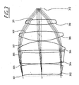
- Reference symbol in FIG. 3 R asphere D [mm] Glass [Mm] 301 ⁇ 3,758 302 666.750 A 34.984 CaF 2 303 -349.228 0,150 304 1146.535 34.985 CaF 2 305 562.165 8.088 306 -1,522.323 30.125 CaF 2 307 -130.620 0.207 308 155.847 31.092 CaF 2 309 -348.755 21.245 310 278.542 16.679 CaF 2 311 -508.154 34.220 312 ⁇
- the surface numbers represent the order of the surfaces in the direction of light.
- Area 301 corresponds to the Aperture plane 213.
- Surface 312 corresponds to the field plane 219.
- the lens section of the field lens 215 is shown in FIG.
- the maxiamle diameter of the illuminated field in the aperture plane is 100mm.
- FIG. 4 shows the illumination of the diaphragm plane 213 for a honeycomb condenser 211 according to Table 1, in which y-field honeycombs 241 and x-field honeycombs 249 are illuminated with an equal width of 4.0 mm.
- the extension of the illumination of the field honeycombs is set by means of the zoom axicon lens 7. Due to the same width of the x and y field honeycombs, a square grid with secondary light sources 402 results.
- the secondary light sources 402 are also square according to the design of the microcylinder lenses. Through the use of a diffuser, which is arranged in the light direction after the plates with field honeycomb, the secondary light sources 402 are illuminated almost homogeneously.
- the discrete illumination of the diaphragm plane 213 due to the micro-cylinder lenses is no longer visible.
- the width ⁇ x of the unlit strips 404 in the y direction and the width ⁇ y of the unlit strips 406 in the x direction between the secondary light sources 402 is the same size and is 0.4 mm in each case.
- the ratio of the strip width to the distance of the unlit strips is thus 10%.
- the circular boundary 408 of the illumination takes place through the circular diaphragm 214 arranged in the diaphragm plane 213.
- the perpendicularly illustrated straight lines 410 and 412 delimit four quadrants which each have the same integral intensity.
- the quadrants bounded by the dashed lines 414 and 416 also have the same integral intensity. In this type of illumination, the integral intensity is the same for two sectors in the diaphragm plane, which can be converted into one another by mirroring on the x and / or y axis.
- FIG. 5 shows a second exemplary embodiment of a honeycomb condenser field lens module 517 in a schematic representation.
- the upper diagram shows a side view (y-z-section), the lower diagram shows a top view (x-y-section).
- the elements corresponding to the elements of Figure 2 in Figure 5 have the same reference numerals as in Figure 2 increased by the number 300. For a description of these elements, reference is made to the description of Figure 2.
- the microcylinder lenses and the field honeycombs are integrated on a plate. This can save a total of four interfaces and reduce the associated transmission losses.
- the plates 235 and 243 with the microcylinder lenses as well as the plates 239 and 247 with the field honeycombs in Figure 2 each have a flat surface. By joining these flat surfaces, the interfaces fall away.
- the structuring of the front surface with the microcylinder lenses and the rear surface with the field honeycombs can also be realized.
- the resulting microcylindrical lens array honeycomb plates 571 and 573 are to be arranged so that the microcylinder lenses 537 and 545 are arranged in the light direction in front of the respective field honeycomb 571 and 549.
- both the y-field honeycombs 541 and the x-field honeycombs 549 are integrated with the respective microcylinder lenses 537 and 545 on one plate each.
- An alternative is also to construct only the y-field honeycombs or only the x-field honeycombs with the microcylinder lenses in one piece.
- two further diaphragm devices 542 and 550 are arranged in addition to the diaphragm device 514.
- the diaphragm devices 542 and 550 it is possible to cover the field honeycomb so that only fully illuminated optical channels are used. Therefore, the areas of the x-field honeycomb 549 and y-field honeycomb 541, which are imaged in the image plane 519 of the illumination system, illuminated in its entire width, whereby the uniformity of the field illumination is improved.
- the aperture device 514 limits the illumination of the diaphragm plane according to the predetermined illumination mode.
- Fig. 6 shows a third embodiment of a honeycomb condenser field lens module 617 in a schematic representation.
- the upper diagram shows a side view (y-z-section), the lower diagram shows a top view (x-y-section).
- the elements corresponding to the elements of Figure 2 in Figure 6 have the same reference numerals as in Figure 2 increased by the number 400. For a description of these elements, reference is made to the description of Figure 2.
- the third embodiment has a plate 675 with toric pupil honeycomb 677 instead of the plate 251 having the y-pupil honeycombs 253 and the plate 255 having the x-pupil honeycombs 257.
- the toric pupilla honeycombs 677 have a collecting effect in both the x and y sections.
- the focal length in the x-section is adapted to the focal length of the x-field honeycombs 649, the focal length in the y-section to the focal length of the y-field honeycombs 641.
- the adjustment of the x- and y-focal length of the toric pupillary honeycomb 677 is carried out such that both the rear meridional focal point and the rear sagittal focal point of y-Feldwabe 641, x-Feldwabe 649 and toric Pupillenwabe 677 channel formed in the diaphragm plane 613, the anterior meridional focal point of this channel at the location of the y-field honeycombs 641, the anterior sagittal focal point of this channel is located at the location of the x-field honeycombs 649.
- the height of the toric pupil honeycomb 677 in the yz section is equal to the width b 1 of the y-field honeycombs 641
- the width of the toric pupil honeycombs 677 in the xz-section is equal to the width b 2 of the x-field honeycombs 649.
- two shutter devices 642 and 540 are arranged which perform the same function as the shutter devices 542 and 550 in the second embodiment.
- FIG. 7 shows a fourth exemplary embodiment of a honeycomb condenser field lens module 717 in a schematic representation.
- the upper diagram shows a side view (yz-section), the lower diagram shows a top view (xy-section).
- the elements corresponding to the elements of Figure 2 in Figure 7 have the same reference numerals as in Figure 2 increased by the number 500. For a description of these elements, reference is made to the description of Figure 2.
- the y-pupil honeycomb 653 and the x-pupil honeycomb 657 are integrated on a plate 679. This can save a total of two interfaces and reduce the associated transmission losses.
- the plate 251 with the y-pupil honeycombs 253 as well as the plate 255 with the x-pupil honeycombs 257 in FIG. 2 each have a planar surface. By joining these flat surfaces, the interfaces fall away.
- the structuring of the front surface of the plate 679 with the y-pupil honeycomb 653 and the rear surface with the x-pupil honeycomb 657 can be realized.
- Fig. 8 shows a fifth embodiment of a honeycomb condenser field lens module 817 in a schematic representation.
- the upper diagram shows a side view (yz-section), the lower diagram shows a top view (xy-section).
- the elements corresponding to the elements of Figure 2 in Figure 8 have the same reference numerals as in Figure 2 increased by the number 600. For a description of these elements, reference is made to the description of Figure 2.
- the structure of the fifth embodiment corresponds to the structure of the first embodiment of FIG. 2 except for the missing plate 251 with y-Pupillenwaben 253. Without the y-Pupillenwaben 253, the illumination is widened in the field plane, since the y-field honeycomb 841 no sharp edges be imaged.
- the image of the on-axis central y-field honeycomb 841 in the y-z section is considered. Therefore, the axis of the optical channel formed of the y-type honeycomb 841, the x-type honeycomb 849, and the x-type honeycomb 857 coincides with the optical axis OA of the honeycomb condenser 811. Since the aperture plane 813 is located in the rear focal point of the optical channel, the beam pairs 859a-b, 861a-b and 863a-b are focused in the aperture plane. The foci for the beam tufts bounded by the beam pairs 861a-b and 863a-b are in each case located at the edge of the optical channel in the diaphragm plane.
- the heavy beams of the beam tufts bounded by the beam pairs 861a-b and 863a-b do not run parallel to the axis of the optical channel in the diaphragm plane 813, as was the case with y-pupil honeycombs 253 in Example 1, but from the axis 869 of the optical beam Channel away. While the angular difference of the beam pairs 859a-b, 861a-b and 863a-b in the aperture plane 813 is the same, the direction of the beam of the radiation bundles delimited by the beam pairs 861a-b and 863a-b is dependent on the location in the diaphragm plane 813.
- the beams 863a and 861b having the maximum beam angles with respect to the optical axis in the diaphragm 813 extend in the fifth embodiment through the upper or lower edge of the illuminated area of the individual optical channels in the diaphragm 813.
- the beams 861b and 863a coincide Propagation by the field lens 815 to the top and bottom of the illuminated field in the field plane 819.
- the top object point in the field plane 819 is illuminated by rays coming from the respective upper edge of the individual optical channels.
- the heavy beam of this bundle of rays corresponds to beam 861b and converges on the optical axis OA.
- the lowest object point in the field plane 819 is illuminated by rays which come from the respective lower edge of the individual optical channels.
- the heavy beam of this bundle of rays corresponds to beam 863a and converges on the optical axis OA.
- the pupil illumination in the field plane 819 is therefore no longer telecentric.
- the heavy-beam angle which indicates the center of gravity of the pupil illumination, shifts according to the extent of the y-field honeycombs 841, or of the optical channels.
- rays 859a, 861a and 863a or 859b, 861b and 863b emanating from an object point on the y-field honeycombs these are no longer focused in the field plane 819.
- the y-field honeycombs 841 are no longer mapped into the field level 819.
- the intensity distribution of the rectangular field is therefore no longer stepped in a section along the y-axis, but has at the edge a transition region in which the intensity decreases linearly.
- the fifth exemplary embodiment in FIG. 8 shows the extreme case in which the intensity distribution of the rectangular field is triangular in a section along the y-axis.
- the intensity increases linearly from zero on both sides of the optical axis from zero to a maximum lying on the optical axis OA.
- the width ⁇ y of the illumination is exactly twice as great as with the use of y-pupil honeycombs 253. This is the case when the beam pairs 861a-b and 863a-b strike the y-field honeycomb at the maximum possible angle of incidence, then that they are focused in the diaphragm plane on the edge of the respective optical channel. If the beam pairs are not focused on the edge of the respective optical channel, but are located between the axis and the edge of the optical channel, the intensity increases in the field plane in a section along the y-axis linear to a plateau, in which the intensity is constant.
- An intensity distribution resulting from the fifth embodiment is sufficient for a scanner lighting system.
- the x-field honeycombs and x-pupil honeycombs generate a constant intensity profile in the x-direction.
- the y direction which in this case is the scan direction, there is a location-dependent profile.
- the scan energy is important, which results as a line integral in the scan direction over the intensity distribution and is nearly the same size for each object point in the field plane 819 due to the constant intensity profile in the x direction.
- FIG. 9 shows a sixth exemplary embodiment of a honeycomb condenser field lens module 917 in a schematic representation.
- the upper diagram shows a side view (y-z-section), the lower diagram shows a top view (x-y-section).
- the elements corresponding to the elements of Figure 2 in Figure 9 have the same reference numerals as in Figure 2 increased by the number 700. For a description of these elements, reference is made to the description of Figure 2.
- the structure of the sixth embodiment is similar to the structure of the fifth embodiment, except that the rear meridional focus of the optical channel formed of y-type honeycomb 941, x-type honeycomb 949 and x-type honeycomb 957 is no longer in the diaphragm 913 plane.
- the optical effect and the arrangement of the y-field honeycombs 941 are determined such that the maximum beam angle beams 961a and 963b with respect to the optical axis in the diaphragm plane intersect the diaphragm plane 913 on the axis 969 of the respective optical channel. This is the case when the distance of the diaphragm plane 913 to the rear meridional focal point of the optical channel is equal to half the meridional focal length.
- the beams 961a and 963b represent the heavy beams of the bundles of rays striking the uppermost and lowermost edges, so that the field plane is illuminated telecentrically.
- the other points in the field plane 919 are also illuminated telecentrically.
- the angular distribution in the aperture plane 913 is location dependent within an optical channel, the intensity distribution to the field edge decreases in the y direction.
- each optical channel is completely illuminated in the diaphragm plane 913, then a y-section in the field plane 919 results in a triangular intensity profile, the width ⁇ y of the illumination being twice as large as when using y-pupil honeycombs 253. If the illumination is not complete, this increases the intensity curve linearly from the field edge to a plateau, within which the intensity profile is constant.
- the surface numbers represent the order of the surfaces in the direction of light.
- Surface 1 corresponds to the plane front surface of the plate 935 with the y microcylinder lenses 937.
- Surface 10 corresponds to the diaphragm plane 913.
- the widths b are the widths of the cylindrical lenses perpendicular to the respective cylinder axes.
- the focal lengths f refer to the individual components.
- the length of the microcylinder lenses, the field honeycomb and the pupil honeycomb is 120 mm. In this case, 400 microcylinder lenses, or 30 field honeycombs or 30 pupil honeycombs are arranged on a plate.
- the diameter of the parallel beam bundle striking the honeycomb condenser field module is 100 mm.
- the divergence of the rays within the beam tuft at the entrance surface of the honeycomb condenser is a maximum of ⁇ 25 mrad.
- the presented embodiments can be used in particular for lighting systems which have a high aspect ratio of the field to be illuminated and operating wavelengths in the VUV, such as 193 nm, 157 nm or 126 nm. At these wavelengths, the absorption in the material is considerable, so that as a mixing element a honeycomb condenser is preferable to a totally reflecting glass rod in terms of transmission losses.
- a honeycomb condenser By splitting the honeycomb panels into arrays with cylinder lenses arranged perpendicular to one another, it is also possible to illuminate fields with a high aspect ratio in the case of components which are easy to produce. It was shown for the first time how the aperture plane can be almost completely illuminated by the use of microcylinder lenses in this type of honeycomb condensers.
Landscapes
- Physics & Mathematics (AREA)
- General Physics & Mathematics (AREA)
- Exposure And Positioning Against Photoresist Photosensitive Materials (AREA)
- Exposure Of Semiconductors, Excluding Electron Or Ion Beam Exposure (AREA)
- Microscoopes, Condenser (AREA)
- Lenses (AREA)
Description
Die vorliegende Erfindung betrifft ein Beleuchtungssystem mit einem Wabenkondensor für eine Mikrolithographie-Projektionsbelichtungsanlage, eine Mikrolithographie-Projektionsbelichtungsanlage umfassend ein Beleuchtungssystem mit einem Wabenkondensor und ein Verfahren zur Herstellung von mikrostrukturierten Bauteilen mit einer Mikrolithographie-Projektionsbelichtungsanlage umfassend ein Beleuchtungssystem mit einem Wabenkondensor.The present invention relates to a lighting system with a honeycomb condenser for a microlithography projection exposure apparatus, a microlithography projection exposure apparatus comprising a honeycomb condenser illumination system and a method for producing microstructured components using a microlithography projection exposure apparatus comprising a honeycomb condenser illumination system.
Aus der US 4,682,885 ist ein gattungsgemäßes Beleuchtungssystem bekannt. Das Licht einer Quecksilberdampf-Lampe wird von einem elliptischen Kollektorspiegel aufgenommen und auf einen optischen Integrator gerichtet, der als spezielle Ausführungsform eines Wabenkondensors ausgebildet ist. Der optische Integrator dient der Lichtmischung und der Erzeugung einer Vielzahl von Lichtbüscheln, die durch eine Kondensoroptik in einer Bildebene überlagert werden und dort ein rechteckförmiges Feld beleuchten. Der optische Integrator besteht dabei aus zwei Paaren von Platten mit Zylinderlinsen, wobei die Zylinderachsen der Zylinderlinsen eines Paares parallel, die Zylinderachsen der Paare zueinander senkrecht ausgerichtet sind. Die beiden Platten eines Paares sind in der gegenseitigen Brennebene der Zylinderlinsen angeordnet. Durch unterschiedlich große Brennweiten der beiden Paare wird in der Bildebene ein rechteckförmiges Feld mit einem Seiten-Aspektverhältnis größer 1:1 beleuchtet.From US 4,682,885 a generic lighting system is known. The light of a mercury vapor lamp is picked up by an elliptical collector mirror and directed to an optical integrator, which is designed as a special embodiment of a honeycomb condenser. The optical integrator is used for the light mixing and the generation of a plurality of tufts of light which are superimposed by a condenser optics in an image plane and illuminate a rectangular field there. The optical integrator consists of two pairs of plates with cylindrical lenses, wherein the cylinder axes of the cylindrical lenses of a pair of parallel, the cylinder axes of the pairs are aligned perpendicular to each other. The two plates of a pair are arranged in the mutual focal plane of the cylindrical lenses. Due to different focal lengths of the two pairs, a rectangular field with a side aspect ratio greater than 1: 1 is illuminated in the image plane.
Aus US 5,926,257 ist ein Beleuchtungssystem mit einem Wabenkondensor bekannt, der einen ähnlichen Aufbau zu dem aus der US 4,682,885 bekannten Wabenkondensor aufweist. Die Zylinderlinsen sind dabei als diffraktive Elemente mit zylindrischer Wirkung ausgebildet.From US 5,926,257 a lighting system with a honeycomb condenser is known, which has a similar structure to that known from US 4,682,885 honeycomb condenser. The cylindrical lenses are designed as diffractive elements with a cylindrical effect.
Die US 5,963,305 beschreibt ebenfalls einen Wabenkondensor aus zwei senkrecht zueinander angeordneten Paaren von Platten mit Zylinderlinsen. Gezeigt werden refraktive und diffraktive Ausführungsformen der Zylinderlinsen.The US 5,963,305 also describes a honeycomb condenser of two mutually perpendicular pairs of plates with cylindrical lenses. Shown are refractive and diffractive embodiments of the cylindrical lenses.
Nachteilig an den in US 4,682,885, US 5,926,257 und US 5,963,305 gezeigten Wabenkondensoren ist die Tatsache, daß die auf den Wabenkondensor folgende Blendenebene des Beleuchtungssystems nur unvollständig ausgeleuchtet wird, wenn das auf den Wabenkondensor treffende Strahlenbüschel nur eine geringe Divergenz aufweist. Ein derartiges Strahlenbüschel, wie es beispielsweise von einer Laserlichtquelle erzeugt wird, wird durch die gekreuzten Zylinderlinsenplatten in eine Vielzahl von Strahlenbüscheln zerlegt, die in die Blendenebene des Beleuchtungssystems fokussiert werden und dort ein Gitter von sekundären Lichtquellen bilden. Die sekundären Lichtquellen sind aufgrund der geringen Divergenz des Strahlenbüschels am Eintritt des Wabenkondensors nur punktförmig. Die Blendenebene ist deshalb nur mit diskreten Intensitätspeaks ausgeleuchtet. Bei den Wabenkondensoren mit refraktiven Zylinderlinsen ist die Anzahl der ausgeleuchteten Zylinderlinsen in der Größenordnung von 101. Deshalb befinden sich in der Blendenebene nur in der Größenordnung 102 sekundäre Lichtquellen. Durch den Einsatz von diffraktiven Elementen mit zylindrischer Wirkung kann zwar die Anzahl der sekundären Lichtquellen auf Grund der geringeren Elementbreite erhöht werden, doch ergeben sich dann durch den sehr großen Abbildungsmaßstab zwischen diffraktiven Elementen und dem auszuleuchtenden Feld sehr hohe Anforderungen an die Qualität der diffraktiven Elemente, insbesondere an die Randschärfe.A disadvantage of the honeycomb condensers shown in US Pat. No. 4,682,885, US Pat. No. 5,926,257 and US Pat. No. 5,963,305 is the fact that the aperture plane of the illumination system following the honeycomb condenser is illuminated only incompletely if the bundle of rays striking the honeycomb condenser has only a slight divergence. Such a bundle of rays, such as is generated by a laser light source, is decomposed by the crossed cylindrical lens plates into a plurality of bundles of rays, which are focused in the diaphragm plane of the illumination system and form a grid of secondary light sources. The secondary light sources are only punctiform due to the low divergence of the ray bundle at the entrance of the honeycomb condenser. The aperture plane is therefore illuminated only with discrete intensity peaks. In the case of the honeycomb condensers with refractive cylindrical lenses, the number of illuminated cylindrical lenses is of the order of 10 1 . Therefore, in the diaphragm plane only in the order of 10 2 secondary light sources. Although the number of secondary light sources can be increased due to the smaller element width by using diffractive elements with a cylindrical effect, the very high magnification between diffractive elements and the field to be illuminated results in very high demands on the quality of the diffractive elements. especially to the edge sharpness.
Da die beiden Paare von Zylinderlinsenplatten in US 4,682,885, US 5,926,257 und US 5,963,305 unterschiedliche Brennweiten aufweisen und die in Lichtrichtung jeweils nachgeordnete Zylinderlinsenplatte eines Paares in der Nähe der Blendenebene angeordnet ist, sind die in Lichtrichtung jeweils vorgeordneten Zylinderlinsenplatten der beiden Paare axial getrennt angeordnet. Wird der Wabenkondensor mit einem Strahlenbüschel endlicher Divergenz beleuchtet, wie es beispielsweise von einer Quecksilberdampf-Lampe erzeugt wird, so führt die axiale Trennung der vorgeordneten Zylinderlinsenplatten zu einer elliptischen Ausleuchtung der Blendenebene. Da für den Einsatz in der Mikrolithographie die Ausleuchtung der Blendenebene möglichst rotationssymmetrisch sein sollte, ist der Einsatz von zusätzlichen Blenden oder Filtern erforderlich, wodurch ein Lichtverlust auftritt.Since the two pairs of cylindrical lens plates in US Pat. No. 4,682,885, US Pat. No. 5,926,257 and US Pat. No. 5,963,305 have different focal lengths and the cylindrical lens plate of a pair in the light direction is arranged in the vicinity of the diaphragm plane, the cylindrical lens plates of the two pairs arranged in the light direction are arranged axially separated from one another. If the honeycomb condenser is illuminated with a bundle of rays of finite divergence, as is generated, for example, by a mercury vapor lamp, then the axial separation of the upstream cylindrical lens plates leads to a elliptical illumination of the aperture plane. Since for use in microlithography, the illumination of the diaphragm plane should be as rotationally symmetrical as possible, the use of additional apertures or filters is required, whereby a loss of light occurs.
Aus US 5,847,746 ist ein Beleuchtungssystem bekannt, das zur Lichtmischung zwei gekreuzte Zylinderlinsenplatten unterschiedlicher Brennweite einsetzt. Die Zylinderlinsenplatten werden dabei mit einem parallelen Lichtbüschel geringer Divergenz beleuchtet. Um zu vermeiden, daß die Blendenebene eines nachfolgenden Projektionsobjektives mit Intensitätspeaks punktuell ausgeleuchtet wird, sind die Brennweiten der beiden Zylinderlinsenplatten so eingestellt, daß die sekundären Lichtquellen in meridionale und sagittale sekundäre Lichtquellen aufgespalten werden, die defokussiert angeordnet sind. Dadurch werden die Intensitätspeaks in der Blendenebene zu Strichen geringerer Maximalintensität auseinandergezogen. Nachteilig an dieser Anordnung ist die nur partielle Ausleuchtung der Blendenebene und die Tatsache, daß die in der Regel gewünschte Punktsymmetrie der Blendenausleuchtung durch die strichförmigen Intensitätspeaks verletzt wird.US Pat. No. 5,847,746 discloses an illumination system which uses two crossed cylindrical lens plates of different focal lengths for light mixing. The cylindrical lens plates are illuminated with a parallel tuft of light divergence. In order to avoid that the aperture plane of a subsequent projection lens with intensity peaks is selectively illuminated, the focal lengths of the two cylindrical lens plates are set so that the secondary light sources are split into meridional and sagittal secondary light sources, which are arranged defocused. As a result, the intensity peaks in the diaphragm plane are pulled apart into lines of lower maximum intensity. A disadvantage of this arrangement, the only partial illumination of the diaphragm plane and the fact that the usually desired point symmetry of the aperture illumination is violated by the line-shaped intensity peaks.
Aus US 5,815,248 ist der Einsatz eines eindimensionalen Gitters vor einem Wabenkondensor bekannt. Der Wabenkondensor besteht nicht aus einzelnen Platten mit Zylinderlinsen, sondern aus einer Platte mit stabförmigen Linsenelementen, die in einem zweidimensionalen Array angeordnet sind. Bei einem zu beleuchtenden Feld mit hohem Seiten-Aspektverhältnis müssen die Linsenelemente ein gleich großes Seiten-Aspektverhältnis aufweisen. Dementsprechend sind die von den Linsenelementen in der Blendenebene erzeugten sekundären Lichtquellen ohne das eindimensionale Gitter ungleichmäßig verteilt. Mit Hilfe des eindimensionalen Gitters wird das Array mit Linsenelementen aus drei in einer Ebene liegenden Richtungen beleuchtet, so daß die Zahl der von dem Array erzeugten sekundären Lichtquellen erhöht wird. Dadurch kann eine gleichmäßigere Verteilung der sekundären Lichtquellen in der auf den Wabenkondensor folgenden Blendenebene erzielt werden. Nachteilig an der Verwendung eines eindimensionalen Gitters ist die Tatsache, daß die Ausleuchtung der Blendenebene aus diskreten Intensitätspeaks besteht und keine homogene Ausleuchtung erzielt wird. Zudem weisen die von den Linsenelementen erzeugten optischen Kanäle ein hohes Seiten-Aspektverhältnis auf, so daß ein Großteil der Lichtkanäle bei der üblichen kreisförmigen Beleuchtung des Wabenkondensors nur unvollständig beleuchtet wird.From US 5,815,248 the use of a one-dimensional grid in front of a honeycomb condenser is known. The honeycomb condenser does not consist of individual plates with cylindrical lenses, but of a plate with rod-shaped lens elements, which are arranged in a two-dimensional array. For a high aspect ratio field to be illuminated, the lens elements must have an equal aspect ratio. Accordingly, the secondary light sources generated by the lens elements in the diaphragm plane are unevenly distributed without the one-dimensional grid. By means of the one-dimensional grid, the array of lens elements is illuminated from three in-plane directions, thus increasing the number of secondary light sources generated by the array. As a result, a more even distribution of the secondary light sources in the diaphragm plane following the honeycomb condenser can be achieved. The disadvantage of using a one-dimensional grating is the fact that the illumination of the diaphragm plane consists of discrete intensity peaks and no homogeneous illumination is achieved. In addition, the optical channels produced by the lens elements have a high aspect ratio, so that a large part of the light channels is illuminated only incompletely in the usual circular illumination of the honeycomb condenser.
Aus der DE 198 55 106 A1 der Anmelderin ist ein Beleuchtungssystem für die VUV-Mikrolithographie mit einem Wabenkondensor als optischem Integrator bekannt. Vor dem Wabenkondensor ist zur Divergenzerhöhung ein Mikrolinsenarray mit rechteckförmigen Einzellinsen angeordnet. Der Wabenkondensor besteht dabei aus zwei in der gegenseitigen Brennebene angeordneten Wabenplatten, die aus einem Array von Einzellinsen oder aus zwei gekreuzten Zylinderlinsenplatten gebildet werden. Die von den Einzellinsen, beziehungsweise den gekreuzten Zylinderlinsen, gebildeten optischen Kanäle weisen dabei ein ähnliches Seiten-Aspektverhältnis wie das auszuleuchtende Feld auf. Um die Blendenebene gleichmäßig beleuchten zu können, müssen die rechteckförmigen Mikrolinsen zur Divergenzerhöhung eine ähnliches Seiten-Aspektverhältnis wie die optischen Kanäle aufweisen. Nachteilig an dieser Anordnung ist, daß bei einem Feld mit einem hohen Seiten-Aspektverhältnis die Einzellinsen ebenfalls ein hohes Seiten-Aspektverhältnis aufweisen müssen. Derartige Einzellinsen sind aufwendig herzustellen. Verwendet man für die Wabenplatten gekreuzte Zylinderlinsenplatten, so ist die Breite der Zylinderlinsen für die beiden Ausrichtungen stark unterschiedlich, wenn die gekreuzten Zylinderlinsen gleiche Brennweite aufweisen. Für die Zylinderlinsenplatten unterschiedlicher Ausrichtung müssen unter Umständen verschiedene Herstellverfahren angewandt werden. Auch bei dieser Konfiguration wird ein Großteil der Lichtkanäle bei der üblichen kreisrunden Beleuchtung des Wabenkondensors nur unvollständig beleuchtet.DE 198 55 106 A1 of the applicant discloses a lighting system for VUV microlithography with a honeycomb condenser as an optical integrator. Before the honeycomb condenser, a microlens array with rectangular individual lenses is arranged to increase the divergence. The honeycomb condenser consists of two arranged in the mutual focal plane honeycomb panels, which are formed from an array of single lenses or two crossed cylindrical lens plates. The optical channels formed by the individual lenses or the crossed cylindrical lenses have a similar aspect ratio as the field to be illuminated. In order to be able to illuminate the aperture plane uniformly, the rectangular divergence increase microlenses must have a similar aspect ratio as the optical channels. A disadvantage of this arrangement is that in a field with a high aspect ratio, the individual lenses must also have a high aspect ratio. Such individual lenses are expensive to produce. If crossed cylinder lens plates are used for the honeycomb panels, the width of the cylindrical lenses for the two orientations is greatly different if the crossed cylindrical lenses have the same focal length. For the cylinder lens plates of different orientation different manufacturing processes may have to be used. Even with this configuration, a large part of the light channels is illuminated only incompletely in the usual circular illumination of the honeycomb condenser.
Ein weiteres Beleuchtungssystem mit einem Wabenkondensor aus zwei senkrecht zueinander angeordneten Paaren von Platten von Zylinderlinsen ist aus JP11121358 A bekannt. Gezeigt werden refraktive Ausführungsformen der Zylinderlinsen.Another illumination system with a honeycomb condenser comprising two mutually perpendicular pairs of plates of cylindrical lenses is known from JP11121358 A. Shown are refractive embodiments of the cylindrical lenses.
Aufgabe der vorliegenden Erfindung ist es deshalb, ein Beleuchtungssystem mit einem Wabenkondensor für eine Mikrolithographie-Projektionsbelichtungsanlage anzugeben, mit dem bei hoher Effizienz die Blendenebene möglichst vollständig und symmetrisch ausleuchtbar ist.The object of the present invention is therefore to specify an illumination system with a honeycomb condenser for a microlithography projection exposure apparatus, with which the aperture plane can be illuminated as completely and symmetrically as possible with high efficiency.
Diese Aufgabe wird durch ein Beleuchtungssystem mit den Merkmalen des Anspruchs 1 und Anspruchs 27 gelöst. Vorteilhafte Ausgestaltungen der Erfindung ergeben sich aus den Merkmalen der abhängigen Ansprüche.This object is achieved by a lighting system with the features of
In dem Beleuchtungssystem werden die von einer Lichtquelle ausgehenden Strahlen von einem ersten Objektiv aufgenommen und formen in der Austrittsebene des ersten Objektives ein Strahlenbündel, das vorzugsweise ein paralleles Strahlenbündel geringer Divergenz ist. Ein Wabenkondensor erzeugt aus dem Strahlenbündel eine Vielzahl von Strahlenbündeln, die durch eine Kondensoroptik in einer Bildebene des Beleuchtungssystems überlagert werden und dort vorzugsweise ein rechteckförmiges Feld ausleuchten. Die längere Feldseite ist in x-Richtung, die kürzere Feldseite in y-Richtung ausgerichtet. In der Bildebene des Beleuchtungssystems ist üblicherweise das Retikel für die Mikrolithographie-Projektionsbelichtungsanlage oder eine Maskiervorrichtung, die mit einem nachfolgenden Objektiv auf das Retikel abgebildet wird, angeordnet. Der Wabenkondensor weist mindestens eine erste und eine zweite Platte mit stabförmigen Zylinderlinsen auf, die senkrecht zur Richtung der Zylinderachsen der Zylinderlinsen aneinandergereiht sind. Die Zylinderlinsen haben vorzugsweise eine zylindrische Vorderfläche und eine plane Rückfläche. Die zylindrische Vorderfläche weist senkrecht zur Zylinderachse eine konvexen Querschnitt und parallel zur Zylinderachse einen planen Querschnitt auf. Die Zylinderachsen der Zylinderlinsen der beiden Platten sind vorzugsweise senkrecht zueinander ausgerichtet. Die Zylinderachsen der Zylinderlinsen der ersten Platte sind in x-Richtung ausgerichtet. Deshalb werden die Zylinderlinsen der ersten Platte im folgenden als y-Feldwaben bezeichnet. Die Zylinderachsen der Zylinderlinsen der zweiten Platte sind in y-Richtung ausgerichtet. Deshalb werden die Zylinderlinsen der zweiten Platte im folgenden als x-Feldwaben bezeichnet. Die y- und x-Feldwaben erzeugen in der auf den Wabenkondensor folgenden Blendenebene ein Gitter von sekundären Lichtquellen. Weist das auf den Wabenkondensor treffende Strahlenbündel eine geringe Divergenz der Strahlwinkel auf, so ist die Ausdehnung der sekundären Lichtquellen gering, und die Blendenebene ist ungleichmäßig mit diskreten Intensitätspeaks beleuchtet. Um eine gleichmäßige Ausleuchtung der Blendenebene zu erreichen, ist vorteilhafterweise in Lichtrichtung vor der Platte mit y-Feldwaben eine dritte Platte mit stabförmigen Zylinderlinsen und in Lichtrichtung vor der Platte mit x-Feldwaben eine vierte Platte mit stabförmigen Zylinderlinsen angeordnet. Die Zylinderlinsen der dritten Platte sind in Richtung der Zylinderachsen gleich lang wie die y-Feldwaben, weisen aber senkrecht zur Richtung der Zylinderachsen eine geringere Breite als die y-Feldwaben auf. Sie werden im folgenden als y-Mikrozylinderlinsen bezeichnet. Die Zylinderachsen der y-Mikrozylinderlinsen sind dabei parallel zu den Achsen der y-Feldwaben ausgerichtet. Die Zylinderlinsen der vierten Platte sind in Richtung der Zylinderachsen gleich lang wie die x-Feldwaben, weisen aber senkrecht zur Richtung der Zylinderachsen eine geringere Breite als die x-Feldwaben auf. Sie werden im folgenden als x-Mikrozylinderlinsen bezeichnet. Die Zylinderachsen der x-Mikrozylinderlinsen sind dabei parallel zu den Achsen der x-Feldwaben ausgerichtet. Die vor den Feldwaben angeordneten Mikrozylinderlinsen führen zu einer Divergenzerhöhung des auf die Feldwaben treffenden Strahlenbündels. Dadurch wird erreicht, daß die Ausdehnung der sekundären Lichtquellen in der Blendenebene erhöht und damit die Blendenebene gleichmäßiger ausgeleuchtet wird. Der Vorteil des Einsatzes von zwei vor den jeweiligen Feldwaben angeordneten Platten mit Mikrozylinderlinsen besteht darin, daß die Divergenzerhöhung jeweils unmittelbar vor den Feldwaben und nur in einer Ebene erfolgt. Die Flächennormale dieser Ebene zeigt dabei in Richtung der Zylinderachsen der Mikrozylinderlinsen und der entsprechenden Feldwaben. Die Mikrozylinderlinsen sind dabei refraktiv oder diffraktiv ausgebildet.In the illumination system, the beams emanating from a light source are picked up by a first objective and form in the exit plane of the first objective a beam which is preferably a parallel divergence beam. A honeycomb condenser generates from the radiation beam a multiplicity of radiation bundles, which are superimposed by a condenser optics in an image plane of the illumination system and there preferably illuminate a rectangular field. The longer field side is aligned in the x direction, the shorter field side in the y direction. In the image plane of the illumination system, the reticle for the microlithography projection exposure apparatus or a masking device, which is imaged onto the reticle with a subsequent objective, is usually arranged. The honeycomb condenser has at least a first and a second plate with rod-shaped cylindrical lenses, which are aligned in a row perpendicular to the direction of the cylinder axes of the cylindrical lenses. The cylindrical lenses preferably have a cylindrical front surface and a flat rear surface. The cylindrical front surface has a convex cross section perpendicular to the cylinder axis and a plane cross section parallel to the cylinder axis. The cylinder axes of the cylindrical lenses of the two plates are preferably aligned perpendicular to each other. The cylinder axes of the cylindrical lenses of the first plate are aligned in the x direction. Therefore, the cylindrical lenses of the first plate will be referred to as y-field honeycombs. The cylinder axes of the cylindrical lenses of the second plate are aligned in the y direction. Therefore, the cylindrical lenses of the second plate are hereinafter referred to as x-field honeycombs. The y and x field honeycombs create a grid of secondary light sources in the aperture plane following the honeycomb condenser. If the beam impinging on the honeycomb condenser has a small divergence of the beam angles, then the extension of the secondary light sources is low and the diaphragm plane is unevenly illuminated with discrete intensity peaks. To uniformly illuminate the aperture plane reach, is advantageously arranged in the light direction in front of the plate with y-field honeycombs a third plate with rod-shaped cylindrical lenses and in the light direction in front of the plate with x-field honeycombs a fourth plate with rod-shaped cylindrical lenses. The cylindrical lenses of the third plate are the same length in the direction of the cylinder axes as the y-field honeycombs, but have a width less perpendicular to the direction of the cylinder axes than the y-field honeycombs. They are referred to below as y microcylinder lenses. The cylinder axes of the y-microcylinder lenses are aligned parallel to the axes of the y-field honeycombs. The cylindrical lenses of the fourth plate are the same length in the direction of the cylinder axes as the x-field honeycombs, but have a smaller width than the x-field honeycombs perpendicular to the direction of the cylinder axes. They are referred to below as x-microcylinder lenses. The cylinder axes of the x-microcylinder lenses are aligned parallel to the axes of the x-field honeycombs. The arranged in front of the field honeycomb microcylinder lenses lead to a Divergenzerhöhung the striking on the field honeycomb beam. This ensures that the expansion of the secondary light sources increases in the diaphragm plane and thus the diaphragm plane is illuminated more uniformly. The advantage of using two plates arranged with microcylinder lenses in front of the respective field honeycombs is that the increase in divergence occurs in each case directly in front of the field honeycombs and only in one plane. The surface normal of this plane points in the direction of the cylinder axes of the micro-cylinder lenses and the corresponding field honeycombs. The microcylinder lenses are formed refractive or diffractive.
Es ist vorteilhaft, wenn die x- und y-Feldwaben ähnliche Breiten senkrecht zu den jeweiligen Zylinderachsen aufweisen. Vorzugsweise sind die Breiten der x- und y-Feldwaben im Rahmen der Fertigungstoleranzen gleich groß. Dadurch läßt sich das gleiche Fertigungsverfahren für x- und y-Feldwaben anwenden. Ein weiterer Vorteil von gleich breiten x- und y-Feldwaben besteht darin, daß die sekundären Lichtquellen in der Blendenebene auf einem quadratischen Gitter zum Liegen kommen. Um bei ähnlichen Breiten für die x- und y-Feldwaben ein rechteckförmiges Feld auszuleuchten, müssen die x- und y-Feldwaben unterschiedliche Brennweiten aufweisen. Da es sich bei den Feldwaben um Zylinderlinsen handelt, bezieht sich die Angabe einer Brennweite für die Feldwaben auf den Flächenschnitt, in dem die Feldwaben eine optische Wirkung aufweisen. Da die kürzere Feldseite in der Bildebene des Beleuchtungssystems in y-Richtung zeigt, muß die Brennweite der y-Feldwaben größer als die Brennweite der x-Feldwaben sein, vorzugsweise größer als das 1.5-fache, besonders bevorzugt größer als das 2-fache.It is advantageous if the x and y field honeycombs have similar widths perpendicular to the respective cylinder axes. Preferably, the widths of the x and y-field honeycombs are the same in the context of manufacturing tolerances. This allows the same manufacturing process for x and y field honeycombs apply. Another advantage of equidistant x- and y-field honeycombs is that the secondary light sources come to rest in the diaphragm plane on a square grid. In order to illuminate a rectangular field for similar widths for the x and y field honeycombs, the x and y field honeycombs must have different focal lengths. Since the field honeycombs are cylindrical lenses, the specification of a focal length for the Field honeycombs on the surface section, in which the field honeycombs have an optical effect. Since the shorter field side in the image plane of the illumination system points in the y direction, the focal length of the y field honeycombs must be greater than the focal length of the x field cells, preferably greater than 1.5 times, particularly preferably greater than 2 times.
Vorzugsweise sollte die Winkelverteilung der auf die Feldwaben treffenden Strahlen an jedem Ort der Feldwaben homogen sein. Da die Mikrozylinderlinsen diskrete Elemente sind, ist dies nicht möglich. Um jedoch die Feldwaben mit einer möglichst ortsunabhängigen Winkelverteilung zu beleuchten, ist es von Vorteil, wenn die Breite der Mikrozylinderlinsen kleiner als die Breite der entsprechenden Feldwaben ist. Vorteilhafterweise beträgt die Breite der Mikrozylinderlinsen weniger als die Hälfte, bevorzugt weniger als 1/5 der Breite der entsprechenden Feldwaben.Preferably, the angular distribution of the rays impinging on the field honeycombs should be homogeneous at each location of the field honeycombs. Since the microcylinder lenses are discrete elements, this is not possible. However, in order to illuminate the field honeycomb with a possible location-independent angular distribution, it is advantageous if the width of the micro-cylindrical lenses is smaller than the width of the corresponding field honeycomb. Advantageously, the width of the microcylinder lenses is less than half, preferably less than 1/5 of the width of the corresponding field honeycomb.
Die von den Feldwaben in der Blendenebene erzeugten sekundären Lichtquellen sind nicht homogen ausgeleuchtet, sondern weisen auf Grund der Rasterung der Mikrozylinderlinsen Intensitätsschwankungen auf. Die Zahl der Intensitätspeaks innerhalb einer sekundären Lichtquelle in einer Richtung entspricht dabei der Zahl der Mikrozylinderlinsen pro Feldwabe. Ist die Zahl der x-Mikrozylinderlinsen pro x-Feldwabe und die Zahl der y-Mikrozylinderlinsen pro y-Feldwabe gleich groß, so weisen die sekundären Lichtquellen in x- und y-Richtung gleich viele Intensitätspeaks auf.The secondary light sources generated by the field honeycombs in the diaphragm plane are not homogeneously illuminated, but have intensity fluctuations due to the screening of the microcylinder lenses. The number of intensity peaks within a secondary light source in one direction corresponds to the number of microcylinder lenses per field honeycomb. If the number of x microcylinder lenses per x field honeycomb and the number of y microcylinder lenses per y field honeycomb are the same, then the secondary light sources have the same number of intensity peaks in the x and y directions.
Die Ausdehnung der sekundären Lichtquellen in der Blendenebene ist durch den maximalen Winkel bezüglich der optischen Achse der auf die Feldwaben treffenden Strahlen und durch den Abstand der Feldwaben von der Blendenebene bestimmt, der nahezu der Brennweite der Feldwaben entspricht. Der maximale Winkel wiederum ist durch Breite und Brennweite der Mikrozylinderlinsen festgelegt. Die Brennweite der Mikrozylinderlinsen bezieht sich auf den Flächenschnitt, in dem die Mikrozylinderlinsen eine optische Wirkung aufweisen. Damit sich die einzelnen sekundären Lichtquellen, deren Abstand in der Blendenebene der Breite der Feldwaben entspricht, nicht überschneiden, muß der maximale Winkel nach oben begrenzt werden. Vorteilhafterweise wird deshalb das Verhältnis von Breite und Brennweite der Mikrozylinderlinsen kleiner als das Verhältnis von Breite und Brennweite der entsprechenden Feldwaben gewählt.The extent of the secondary light sources in the diaphragm plane is determined by the maximum angle with respect to the optical axis of the beams hitting the field honeycombs and by the distance of the field honeycombs from the diaphragm plane, which corresponds to almost the focal length of the field honeycomb. The maximum angle, in turn, is determined by the width and focal length of the microcylinder lenses. The focal length of the microcylinder lenses refers to the area intersection in which the microcylinder lenses have an optical effect. So that the individual secondary light sources whose distance in the diaphragm plane corresponds to the width of the field honeycomb do not overlap, the maximum angle must be limited to the top. Advantageously, therefore, the ratio of width and focal length of the micro-cylindrical lenses is chosen smaller than the ratio of width and focal length of the corresponding field honeycomb.
Andererseits soll die Blendenebene möglichst homogen ausgeleuchtet sein. Deshalb sollte der maximale Winkel der auf die Feldwabe treffenden Strahlen bezüglich der optischen Achse eine Mindestwert aufweisen. Es ist vorteilhaft, wenn die Ausdehnung der sekundären Lichtquellen mindestens dem halben Abstand der sekundären Lichtquellen entspricht. Dies ist dann der Fall, wenn das Verhältnis von Breite und Brennweite der Mikrozylinderlinsen mindestens die Hälfte des Verhältnisses von Breite und Brennweite der entsprechenden Feldwaben beträgt.On the other hand, the aperture plane should be illuminated as homogeneously as possible. Therefore, the maximum angle of the rays impinging on the field honeycomb should have a minimum value with respect to the optical axis. It is advantageous if the extent of the secondary light sources corresponds to at least half the distance of the secondary light sources. This is the case when the ratio of width and focal length of the micro-cylinder lenses is at least half the ratio of width and focal length of the respective field honeycomb.
Da an jeder Grenzfläche zwischen Materialien unterschiedlicher Brechzahl Reflexionsverluste auftreten, sollte die Zahl der Grenzflächen so gering wie möglich gehalten werden. Gerade bei Wellenlängen unter 200 nm ist es ein Ziel, die Zahl der optischen Elemente so gering wie möglich zu halten. Es ist deshalb besonders vorteilhaft, die Platte mit den y-Mikrozylinderlinsen und die Platte mit den entsprechenden y-Feldwaben und/oder die Platte mit den x-Mikrozylinderlinsen und die Platte mit den entsprechenden x-Feldwaben jeweils zu einer auf Vorder- und Rückfläche strukturierten Platte zu vereinigen, beispielsweise durch Ansprengen oder über eine Kittfläche. Ebenso ist die gleichzeitige Strukturierung von Vorder- und Rückfläche einer Platte möglich. Dadurch lassen sich für jede einteilig aufgebaute Mikrozylinderlinsen-Feldwaben-Platte zwei Grenzflächen einsparen.Since reflection losses occur at each interface between materials of different refractive index, the number of interfaces should be kept as low as possible. Especially at wavelengths below 200 nm, it is a goal to keep the number of optical elements as small as possible. It is therefore particularly advantageous to pattern the plate with the y-microcylinder lenses and the plate with the corresponding y-field honeycombs and / or the plate with the x-microcylinder lenses and the plate with the corresponding x-field honeycombs respectively on a front and back surface Unite plate, for example by wringing or on a cemented surface. Likewise, the simultaneous structuring of the front and rear surfaces of a plate is possible. As a result, it is possible to save two interfaces for each integral microcylinder lens field honeycomb plate.
Es ist vorteilhaft, wenn die Blendenebene frei zugänglich ist, um in der Blendenebene Blendeneinrichtungen oder Kontrolleinrichtungen für Meßzwecke zu installieren. Der freie Arbeitsabstand sollte in Lichtrichtung vor der Blendenebene mindestens 1.0 mm, bevorzugt mindestens 1.5 mm betragen. Nach der Blendenebene sollte der freie Arbeitsabstand mindestens 1 mm, bevorzugt 3 mm betragen.It is advantageous if the diaphragm plane is freely accessible in order to install diaphragm devices or measuring devices in the diaphragm plane for measuring purposes. The free working distance should be at least 1.0 mm, preferably at least 1.5 mm, in the light direction in front of the diaphragm plane. After the diaphragm plane, the free working distance should be at least 1 mm, preferably 3 mm.
Mit den Blendeneinrichtungen in der Blendenebene ist die Ausleuchtung der Blendenebene und damit auch die Pupillenausleuchtung steuerbar. Übliche Blendeneinrichtungen haben eine kreisrunde Öffnung für eine sogenannte konventionelle Pupillenausleuchtung oder zwei beziehungsweise vier punktsymmetrisch zur Blendenmitte angeordnete Öffnungen für eine sogenannte Dipol- beziehungsweise Quadrupol-Pupillenausleuchtung.With the diaphragm devices in the diaphragm plane, the illumination of the diaphragm plane and thus also the pupil illumination can be controlled. Conventional diaphragm devices have a circular opening for a so-called conventional pupil illumination or two or four points symmetrically arranged to the diaphragm center openings for a so-called dipole or quadrupole pupil illumination.
Mit weiteren Blendeneinrichtungen unmittelbar vor oder hinter den Feldwaben sind einzelne Feldwaben ganz oder teilweise ausblendbar. Dadurch ist es möglich, daß nur die Bereiche der Feldwaben an der Ausleuchtung der Blendenebene teilhaben, die auf ihrer ganzen Breite beleuchtet sind. Dies führt zu einer gesteigerten Uniformität der Ausleuchtung der Bildebene des Beleuchtungssystems.With further diaphragm devices immediately in front of or behind the field honeycombs, individual field honeycombs can be completely or partially faded out. This makes it possible that only the areas of the field honeycombs participate in the illumination of the diaphragm plane, which are illuminated over its entire width. This leads to an increased uniformity of the illumination of the image plane of the lighting system.
Um die x-Feldwaben und die y-Feldwaben bei ausgedehnten sekundären Lichtquellen möglichst randscharf in die Bildebene des Beleuchtungssystems abbilden zu können, ist es vorteilhaft, wenn der Wabenkondensor eine Platte mit einer zweidimensionalen Anordnung von torischen Linsen aufweist. Jede torische Linse bildet zusammen mit einer y-Feldwabe und einer x-Feldwabe einen optischen Kanal. Der optische Kanal umfaßt dabei nicht die gesamte y- und x-Feldwabe, sondern nur den Bereich der Feldwaben, der sich bei einer Projektion in Lichtrichtung als Schnittmenge der beiden gekreuzt angeordneten y- und x-Feldwaben mit der torischen Linse ergibt. Der optische Kanal weist in seiner Mitte eine zur optischen Achse des Wabenkondensors parallele gerade Achse auf, auf der y-Feldwabe, x-Feldwabe und torische Linse angeordnet sind und die torische Linse im Flächenscheitel schneidet. Die optischen Kanäle sind entsprechend der Breiten der Feldwaben rechteckig, bei gleicher Feldwabenbreite quadratisch begrenzt. Die beiden Hauptachsen der torischen Linsen sind so ausgerichtet, daß die eine Hauptachse parallel zu den Zylinderachsen der y-Feldwaben und die andere Hauptachse parallel zu den Zylinderachsen der x-Feldwaben verläuft.In order to be able to image the x-field honeycombs and the y-field honeycombs as sharply as possible into the image plane of the illumination system with extended secondary light sources, it is advantageous if the honeycomb condenser has a plate with a two-dimensional arrangement of toric lenses. Each toric lens forms an optical channel together with a y-field honeycomb and an x-field honeycomb. The optical channel does not include the entire y- and x-field honeycomb, but only the area of the field honeycomb, which results in a projection in the light direction as an intersection of the two crossed arranged y- and x-field honeycombs with the toric lens. The optical channel has in its center a straight axis parallel to the optical axis of the honeycomb condenser, on which the y-field honeycomb, the x-field honeycomb and the toric lens are arranged and which intersects the toric lens in the surface apex. The optical channels are rectangular according to the widths of the field honeycomb, square with the same field width. The two major axes of the toric lenses are aligned so that one main axis is parallel to the cylinder axes of the y-field honeycombs and the other major axis is parallel to the cylinder axes of the x-field honeycombs.
Es ist vorteilhaft, die optischen Wirkungen der y-Feldwaben, x-Feldwaben und torischen Linsen derart auszulegen, daß die hinteren Brennpunkte der aus einer y-Feldwabe, einer x-Feldwabe und einer torischen Linse gebildeten optischen Kanäle in der Nähe der Blendenebene liegen. Dadurch wird ein auf den Wabenkondensor treffendes paralleles Strahlenbündel zunächst in eine Vielzahl von Strahlenbündeln zerlegt und diese in die Blendenebene oder in deren Nähe fokussiert, wodurch dort die sekundären Lichtquellen erzeugt werden.It is advantageous to design the optical effects of the y-field honeycombs, x-field honeycombs and toric lenses such that the back focal points are those of a y-field honeycomb, an x-field honeycomb and a toric lens formed optical channels in the vicinity of the diaphragm plane. As a result, a parallel radiation beam impinging on the honeycomb condenser is first decomposed into a multiplicity of radiation bundles and these are focused in the diaphragm plane or in its vicinity, whereby the secondary light sources are generated there.
Die Verwendung von Zylinderlinsen beziehungsweise von torischen Linsen legt die Betrachtung in zwei senkrecht zueinander stehenden Ebenen nahe. Eine Ebene, deren Flächennormale in Richtung der Zylinderachse der y-Feldwaben eines optischen Kanals zeigt und welche die Achse des betrachteten optischen Kanals beinhaltet, wird im folgenden als "Meridionalebene" bezeichnet. Optische Größen wie Brennpunkt und Brennweite für einen betrachteten optischen Kanal erhalten das Attribut "meridional", wenn sie durch Strahlen bestimmt werden, die ausschließlich in der Meridionalebene verlaufen. Eine Ebene, deren Flächennormale in Richtung der Zylinderachse der x-Feldwaben eines optischen Kanals zeigt und welche die Achse des betrachteten optischen Kanals beinhaltet, wird im folgenden als "Sagittalebene" bezeichnet. Optische Größen wie Brennpunkt und Brennweite für einen betrachteten optischen Kanal erhalten das Attribut "sagittal", wenn sie durch Strahlen bestimmt werden, die ausschließlich in der Sagittalebene verlaufen.The use of cylindrical or toric lenses suggests viewing in two mutually perpendicular planes. A plane whose surface normal points in the direction of the cylinder axis of the y-field honeycombs of an optical channel and which includes the axis of the optical channel under consideration is referred to below as the "meridional plane". Optical magnitudes such as focal point and focal length for a considered optical channel are given the attribute "meridional" when determined by rays that run exclusively in the meridional plane. A plane whose surface normal points in the direction of the cylinder axis of the x-field honeycombs of an optical channel and which includes the axis of the optical channel under consideration is referred to below as the "sagittal plane". Optical magnitudes such as focus and focal length for a given optical channel are given the attribute "sagittal" when determined by rays that pass exclusively in the sagittal plane.
Die Mikrozylinderlinsen werden bei der Bestimmung der optischen Größen für die optischen Kanäle nur mit ihrer mittleren Dicke als Planplatten ohne ihre Zylinderwirkung berücksichtigt. Die Bestimmung der Brennweite oder des Brennpunktes eines optischen Kanals schließt deshalb die als Planplatte berücksichtigten y- und x-Mikrozylinderlinsen mit ein. Der Einfluß dieser äquivalenten Planplatten auf die Brennweiten und Brennpunkte ist jedoch gering.The microcylinder lenses are taken into account in the determination of the optical quantities for the optical channels only with their average thickness as flat plates without their cylinder effect. The determination of the focal length or focal point of an optical channel therefore includes the y and x microcylinder lenses considered as a plane plate. However, the influence of these equivalent plane plates on the focal lengths and focal points is low.
Es ist vorteilhaft, die optischen Wirkungen der y-Feldwaben und des in y-Richtung weisenden Schnittes der torischen Linsen derart auszulegen, daß sich die meridionalen vorderen Brennpunkte am Ort der y-Feldwaben befinden. Da sich der hintere Brennpunkt der auf die Blendenebene folgenden Kondensoroptik in der Bildebene des Beleuchtungssystems befindet, ergibt sich im Meridionalschnitt eine optisch konjugierte Anordnung von y-Feldwaben und Bildebene. Die y-Feldwaben werden deshalb in die Bildebene abgebildet. Gleichzeitig ist es vorteilhaft, wenn die optischen Wirkungen der x-Feldwaben und des in x-Richtung weisenden Schnittes der torischen Linsen derart ausgelegt sind, daß sich die sagittalen vorderen Brennpunkte am Ort der x-Feldwaben befinden. Somit werden die x-Feldwaben ebenfalls in die Bildebene abgebildet. Das auszuleuchtende Feld in der Bildebene ist durch diese Maßnahmen randscharf begrenzt. Durch die Überlagerung der Vielzahl von Strahlenbündeln wird zudem eine sehr homogene Ausleuchtung des Feldes erreicht. Da die torischen Linsen den größten Teil der optischen Wirkung zur Abbildung der Feldwaben beitragen und in der Nähe der Blendenebene angeordnet sind, werden sie im folgenden als Pupillenwaben bezeichnet.It is advantageous to interpret the optical effects of the y-field honeycombs and the y-directional section of the toric lenses so that the meridional front focal points are located at the location of the y-field honeycombs. Because the rear focal point the condenser optics following the diaphragm plane is located in the image plane of the illumination system, the meridional section results in an optically conjugate arrangement of y field cells and image plane. The y-field honeycombs are therefore mapped into the image plane. At the same time, it is advantageous if the optical effects of the x-field honeycombs and the x-directional section of the toric lenses are designed so that the sagittal front focal points are at the location of the x-field honeycombs. Thus, the x-field combs are also mapped into the image plane. The field to be illuminated in the image plane is limited sharply by these measures. Due to the superposition of the plurality of radiation beams, a very homogeneous illumination of the field is also achieved. Since the toric lenses contribute most of the optical effect for imaging the field honeycombs and are arranged near the diaphragm plane, they are referred to below as pupil honeycombs.
Anstelle der Platte mit einer zweidimensionalen Anordnung von torischen Linsen kann insbesondere für eine als Scanner ausgelegte Mikrolithographie-Projektionsbelichtungsanlage der Wabenkondensor eine weitere Platte mit Zylinderlinsen aufweisen, deren Zylinderachsen parallel zu den Zylinderachsen der x-Feldwaben ausgerichtet sind. Diese Zylinderlinsen werden im folgenden als x-Pupillenwaben bezeichnet. Die x-Pupillenwaben haben vorzugsweise eine plane und eine zylindrische Fläche. Die zylindrische Fläche weist senkrecht zur Zylinderachse einen konvexen Querschnitt und parallel zur Zylinderachse einen planen Querschnitt auf. Die zylindrische Fläche ist dabei vorzugsweise der Blendenebene zugewandt. Jede x-Pupillenwabe bildet zusammen mit einer y-Feldwabe und einer x-Feldwabe einen optischen Kanal. Der optische Kanal umfaßt dabei nicht die gesamte y-Feldwabe, x-Feldwabe und x-Pupillenwabe, sondern nur den Bereich der Feldwaben und der x-Pupillenwabe, der sich bei einer Projektion in Lichtrichtung als Schnittmenge der beiden gekreuzt angeordneten y- und x-Feldwaben und der x-Pupillenwabe ergibt. Der optische Kanal weist in seiner Mitte eine zur optischen Achse des Wabenkondensors parallel verlaufende gerade Achse auf, auf der y-Feldwabe, x-Feldwabe und x-Pupillenwabe angeordnet sind. Damit die sekundären Lichtquellen in der Blendenebene oder in deren Nähe zum Liegen kommen, ist es vorteilhaft, wenn sich die hinteren Brennpunkte der optischen Kanäle dort befinden.Instead of the plate having a two-dimensional arrangement of toric lenses, the honeycomb condenser may have, in particular for a microlithography projection exposure apparatus designed as a scanner, another plate with cylindrical lenses whose cylinder axes are aligned parallel to the cylinder axes of the x-field honeycombs. These cylindrical lenses are referred to below as x-pupil honeycombs. The x-pupil honeycombs preferably have a plane and a cylindrical surface. The cylindrical surface has a convex cross section perpendicular to the cylinder axis and a plane cross section parallel to the cylinder axis. The cylindrical surface is preferably facing the diaphragm plane. Each x-pupil honeycomb forms an optical channel together with a y-field honeycomb and an x-field honeycomb. In this case, the optical channel does not include the entire y-field honeycomb, x-field honeycomb and x-pupil honeycomb, but only the area of the field honeycombs and the x-pupil honeycomb which, in the case of a projection in the direction of light, intersects the two crossed y and x Field honeycomb and the x-Pupillenwabe results. The optical channel has in its center a straight axis parallel to the optical axis of the honeycomb condenser on which y-field honeycomb, x-field honeycomb and x-pupil honeycomb are arranged. So that the secondary Light sources come to lie in the diaphragm plane or in the vicinity, it is advantageous if the rear focal points of the optical channels are located there.
Es ist weiterhin vorteilhaft, wenn die optische Wirkung der x-Feldwaben und der x-Pupillenwaben so ausgelegt sind, daß sich die sagittalen vorderen Brennpunkte am Ort der x-Feldwaben befinden. Die x-Pupillenwaben und die auf die Blendenebene folgende Kondensoroptik bilden dann im Sagittalschnitt die x-Feldwaben in die Bildebene nahezu randscharf ab.It is also advantageous if the optical effect of the x-field honeycombs and the x-pupil honeycombs are designed so that the sagittal front focal points are located at the location of the x-field honeycombs. The x-pupil honeycombs and the condenser optics following the diaphragm plane then form the x-field honeycombs in the image plane almost edge-sharply in the sagittal section.
Damit die Schwerstrahlen der Strahlenbüschel in der Bildebene des Beleuchtungssystems nahezu parallel zur optischen Achse verlaufen, ist es vorteilhaft, die optische Wirkung der y-Feldwaben derart auszulegen, daß der Abstand zwischen der Blendenebene und den hinteren meridionalen Brennpunkten nahezu gleich der halben meridionalen Brennweite ist.In order that the beams of the ray bundles in the image plane of the illumination system run almost parallel to the optical axis, it is advantageous to interpret the optical effect of the y-field honeycombs such that the distance between the diaphragm plane and the rear meridional focal points is almost equal to half the meridional focal length.
Wabenkondensoren, die neben den y- und x-Feldwaben nur x-Pupillenwaben aufweisen, lassen sich vorteilhaft in als Scanner ausgelegten Mikrolithographie-Projektionsbelichtungsanlagen einsetzen. Bei diesen Systemen muß nur die kurze Feldseite des auszuleuchtenden Feldes, die in Scan-Richtung verläuft, randscharf begrenzt sein. In Scan-Richtung, also der y-Richtung ist ein sanfter Anstieg der Intensität bei gepulsten Lichtquellen, wie Laser-Lichtquellen sogar vorteilhaft, um Puls-Quantisierungseffekte zu reduzieren.Honeycomb condensers, which have only x-pupil honeycombs in addition to the y and x-field honeycombs, can advantageously be used in microlithography projection exposure apparatuses designed as scanners. In these systems, only the short field side of the field to be illuminated, which runs in the scan direction, must be limited in edge sharpness. In the scan direction, ie the y-direction, a gentle increase in intensity is even advantageous in the case of pulsed light sources, such as laser light sources, in order to reduce pulse quantization effects.
Für eine randscharfe Begrenzung des ausgeleuchteten Feldes auch in y-Richtung ist es vorteilhaft, wenn der Wabenkondensor neben der Platte mit den x-Pupillenwaben eine weitere Platte mit Zylinderlinsen aufweist, deren Zylinderachsen parallel zu den Zylinderachsen der y-Feldwaben ausgerichtet sind. Diese Zylinderlinsen werden im folgenden als y-Pupillenwaben bezeichnet. Die y-Pupillenwaben haben vorzugsweise eine plane und eine zylindrische Fläche. Die zylindrische Fläche weist senkrecht zur Zylinderachse eine konvexen Querschnitt und parallel zur Zylinderachse einen planen Querschnitt auf. Die zylindrische Fläche ist dabei vorzugsweise der Blendenebene zugewandt.For a sharp boundary of the illuminated field in the y-direction, it is advantageous if the honeycomb condenser next to the plate with the x-Pupillenwaben another plate with cylindrical lenses whose cylinder axes are aligned parallel to the cylinder axes of the y-field honeycombs. These cylindrical lenses are referred to below as y-pupil honeycombs. The y-pupil honeycombs preferably have a plane and a cylindrical surface. The cylindrical surface has a convex cross section perpendicular to the cylinder axis and a plane parallel to the cylinder axis Cross-section on. The cylindrical surface is preferably facing the diaphragm plane.
Jede y-Pupillenwabe bildet zusammen mit einer x-Pupillenwabe, einer x-Feldwabe und einer y-Feldwabe einen optischen Kanal. Der optische Kanal umfaßt dabei nicht die gesamte y-Pupillenwabe, x-Pupillenwabe, x-Feldwabe und y-Feldwabe, sondern nur den Bereich der Feldwaben und der Pupillenwaben, der sich bei einer Projektion in Lichtrichtung als Schnittmenge der ausgewählten Feld- und Pupillenwaben ergibt. Der optische Kanal weist in seiner Mitte eine parallel zur optischen Achse des Wabenkondensors verlaufende gerade Achse auf, auf der y-Feldwabe, x-Feldwabe, x-Pupillenwabe und y-Pupillenwabe angeordnet sind. Damit die sekundären Lichtquellen in der Blendenebene oder in deren Nähe zum Liegen kommen, ist es vorteilhaft, wenn sich die hinteren Brennpunkte der optischen Kanäle dort befinden.Each y-pupil honeycomb forms an optical channel together with an x-pupil honeycomb, an x-honeycomb and a y-honeycomb. In this case, the optical channel does not include the entire y-pupil honeycomb, x-pupil honeycomb, x-field honeycomb and y-field honeycomb, but only the region of the field honeycombs and the pupil honeycomb which, when projected in the light direction, results as an intersection of the selected field and pupil honeycombs , The optical channel has in its center a straight axis parallel to the optical axis of the honeycomb condenser on which y-field honeycomb, x-field honeycomb, x-pupil honeycomb and y-pupil honeycomb are arranged. In order for the secondary light sources to come to rest in the diaphragm plane or in its vicinity, it is advantageous if the rear focal points of the optical channels are located there.
Zur randscharfen Begrenzung des ausgeleuchteten Feldes in der Bildebene des Beleuchtungssystems ist es vorteilhaft, wenn sich die vorderen meridionalen Brennpunkte der optischen Kanäle am Ort der y-Feldwaben und die vorderen sagittalen Brennpunkte der optischen Kanäle am Ort der x-Feldwaben befinden.For the sharp boundary of the illuminated field in the image plane of the illumination system, it is advantageous if the front meridional focal points of the optical channels at the location of the y-field honeycombs and the front sagittal focal points of the optical channels are located at the location of the x-field honeycombs.
Ähnlich wie bei dem Wabenkondensor mit den aus torischen Linsen gebildeten Pupillenwaben ist es vorteilhaft, wenn die y-Feldwaben, die x-Feldwaben, die x-Pupillenwaben und die y-Pupillenwaben die gleiche Breite aufweisen. Dann sind die optischen Kanäle quadratisch begrenzt und die sekundären Lichtquellen in der Retikelebene liegen auf einem quadratischen Gitter.Similar to the honeycomb condenser with the pupil honeycombs formed of toric lenses, it is preferable that the y-field honeycombs, the x-field honeycombs, the x-pupil honeycombs, and the y-pupil honeycombs have the same width. Then the optical channels are square-shaped and the secondary light sources in the reticle plane lie on a square grid.
Damit die Blendenebene zugänglich ist, sind die Pupillenwaben in einem endlichen Abstand zur Blendenebene angeordnet. Dies führt zu unbeleuchteten Bereichen zwischen den sekundären Lichtquellen, selbst wenn mit Hilfe der x-Mikrozylinderlinsen und der y-Mikrozylinderlinsen die Pupillenwaben bis zum Rand jedes optischen Kanals ausgeleuchtet sind. Die unbeleuchteten Bereiche bilden unbeleuchtete Streifen parallel zu den Zylinderachsen der x- und y-Feldwaben. Die unbeleuchteten Streifen in x-Richtung sind im Abstand der Breite der y-Feldwaben, die unbeleuchteten Streifen in y-Richtung sind im Abstand der Breite der x-Feldwaben angeordnet. Um die Blendenebene möglichst vollständig auszuleuchten, sind die Breiten der unbeleuchteten Streifen kleiner als 20% des Abstandes von benachbarten unbeleuchteten Streifen.So that the diaphragm plane is accessible, the pupil honeycombs are arranged at a finite distance from the diaphragm plane. This results in non-illuminated areas between the secondary light sources, even if the pupil honeycombs are illuminated to the edge of each optical channel with the aid of the x-microcylinder lenses and the y-microcylinder lenses. The unlit areas form unlit strips parallel to the cylinder axes of the x and y field honeycombs. The unlit strips in the x-direction are at a distance from the width of the y-field honeycombs, the unlit strips in the y-direction are arranged at a distance from the width of the x-field honeycombs. To illuminate the aperture plane as completely as possible, the widths of the unlit strips are less than 20% of the distance from adjacent unlit strips.
Es ist weiterhin vorteilhaft, die Breite dieser unbeleuchteten Streifen gleich groß zu wählen, unabhängig davon, ob sie in Richtung der Zylinderachsen der y-Feldwaben oder der x-Feldwaben zeigen. Neben einer zur Blendenmitte punktsymmetrischen Ausleuchtung der Blendenebene erreicht man damit, daß zwei Sektoren, die durch Spiegelung an der x- und/oder y-Achse ineinander übergeführt werden können, mit der gleichen integralen Intensität beleuchtet werden. So weist jeder durch die x- und y-Achse begrenzte Quadrant oder jeder Quadrant, der durch zwei unter 45° zur x- und y-Achse liegenden Geraden begrenzt wird, die gleiche integrale Intensität auf. Die Blendenebene wird in diesem Fall spiegelsymmetrisch zur x- und y-Achse beleuchtet. Durch die derart ausgeleuchtete Blendenebene werden senkrecht aufeinander stehende Strukturen des nachfolgenden Retikels mit gleicher Qualität auf den Wafer abgebildet.It is also advantageous to choose the width of these unlit strips the same size, regardless of whether they point in the direction of the cylinder axes of the y-field honeycomb or the x-field honeycombs. In addition to a mid-point symmetrical illumination of the diaphragm plane is achieved so that two sectors that can be converted by mirroring on the x and / or y-axis into each other, are illuminated with the same integral intensity. Thus, each quadrant bounded by the x and y axes, or each quadrant bounded by two lines at 45 ° to the x and y axes, has the same integral intensity. In this case, the diaphragm plane is illuminated in mirror symmetry to the x and y axes. By thus illuminated aperture plane perpendicular structures of the following reticle with the same quality are imaged on the wafer.
Um die Reflektionsverluste an Grenzflächen zu reduzieren, ist es vorteilhaft, die x-Pupillenwaben und die y-Pupillenwaben zu vereinigen oder als beidseitig strukturierte Platte aufzubauen.In order to reduce the reflection losses at interfaces, it is advantageous to combine the x-pupil honeycombs and the y-pupil honeycombs or to build them up as a plate structured on both sides.
Ein Beleuchtungssystem mit einem der zuvor beschriebenen Wabenkondensoren läßt sich besonders gut in einer Mikrolithographie-Projektionsbelichtungsanlage einsetzen. In der Bildebene oder in einer dazu konjugierten Ebene des Beleuchtungssystems wird dann das Retikel angeordnet, das die abzubildenden Strukturen aufweist. Um die Größe des ausgeleuchteten Bereiches auf dem Retikel zu variieren, ist es vorteilhaft, wenn in der Bildebene des Beleuchtungssystems eine Maskierungseinrichtung angebracht ist, die mit einem Objektiv auf das Retikel abgebildet wird. Auf das Retikel folgt ein Projektionsobjektiv, das die Strukturen des Retikels auf ein lichtempfindliches Objekt, beispielsweise einen Wafer, abbildet. Derartige Projektionsobjektive sind beispielsweise aus US 5,402,267 (DE 4203464 A) bekannt.An illumination system with one of the previously described honeycomb condensers can be used particularly well in a microlithography projection exposure apparatus. In the image plane or in a plane conjugate to the illumination system, the reticle is then arranged, which has the structures to be imaged. In order to vary the size of the illuminated area on the reticle, it is advantageous if in the image plane of the illumination system, a masking device is mounted, which is imaged with a lens on the reticle. The reticle is followed by a projection objective which focuses the structures of the reticle on a photosensitive object, For example, a wafer maps. Such projection lenses are known for example from US 5,402,267 (DE 4203464 A).
Mit einer derartig ausgestalteten Mikrolithographie-Projektionsbelichtungsanlage lassen sich mikrostrukturierte Bauteile mit Strukturen kleiner 500nm, bevorzugt kleiner 200nm herstellen.With such a microlithography projection exposure apparatus, it is possible to produce microstructured components having structures smaller than 500 nm, preferably smaller than 200 nm.
Nachfolgend werden Einzelheiten der Erfindung anhand der in den Figuren dargestellten Ausführungsbeispiele näher erläutert. Im einzelnen zeigen:
- Figur 1:
- eine schematische Darstellung eines Beleuchtungssystems mit einem ersten Ausführungsbeispiel für ein Wabenkondensor-Feldlinse-Modul;
- Figur 2:
- eine schematische Darstellung eines ersten Ausführungsbeispiels für ein Wabenkondensor-Feldlinse-Modul;
- Figur 3:
- einen Linsenschnitt für eine asphärische Feldlinse;
- Figur 4:
- die Ausleuchtung der Blendenebene des Beleuchtungssystems mit einem Wabenkondensor-Feldlinse-Modul gemäß dem ersten Ausführungsbeispiel;
- Figur 5:
- eine schematische Darstellung eines zweiten Ausführungsbeispiels für ein Wabenkondensor-Feldlinse-Modul;
- Figur 6:
- eine schematische Darstellung eines dritten Ausführungsbeispiels für ein Wabenkondensor-Feldlinse-Modul;
- Figur 7:
- eine schematische Darstellung eines vierten Ausführungsbeispiels für ein Wabenkondensor-Feldlinse-Modul;
- Figur 8:
- eine schematische Darstellung eines fünften Ausführungsbeispiels für ein Wabenkondensor-Feldlinse-Modul; und
- Figur 9:
- eine schematische Darstellung eines sechsten Ausführungsbeispiels für ein Wabenkondensor-Feldlinse-Modul;
- FIG. 1:
- a schematic representation of a lighting system with a first embodiment of a honeycomb condenser field lens module;
- FIG. 2:
- a schematic representation of a first embodiment of a honeycomb condenser field lens module;
- FIG. 3:
- a lens section for an aspherical field lens;
- FIG. 4:
- the illumination of the diaphragm plane of the illumination system with a honeycomb condenser field lens module according to the first embodiment;
- FIG. 5:
- a schematic representation of a second embodiment of a honeycomb condenser field lens module;
- FIG. 6:
- a schematic representation of a third embodiment of a honeycomb condenser field lens module;
- FIG. 7:
- a schematic representation of a fourth embodiment of a honeycomb condenser field lens module;
- FIG. 8:
- a schematic representation of a fifth embodiment of a honeycomb condenser field lens module; and
- FIG. 9:
- a schematic representation of a sixth embodiment of a honeycomb condenser field lens module;
Fig. 1 zeigt in schematischer Darstellung eine Mikrolithographie-Projektionsbelichtungsanlage von der Lichtquelle 1 bis zum Wafer 33. Die obere Darstellung zeigt eine Seitenansicht (y-z-Schnitt), die untere Darstellung eine Draufsicht (x-y-Schnitt). Als Lichtquelle 1 kann unter anderem ein DUV- oder VUV-Laser eingesetzt werden, beispielsweise ein ArF-Laser für 193nm, ein F2-Laser für 157nm, ein Ar2-Laser Für 126nm und ein NeF-Laser für 109nm. Durch eine Strahlformungsoptik 3 wird ein paralleles Lichtbündel erzeugt, das auf ein Divergenz erhöhendes optisches Element 5 trifft. Als Divergenz erhöhendes optisches Element 5 kann beispielsweise eine Rasterplatte aus diffraktiven oder refraktiven Rasterelementen eingesetzt werden. Jedes Rasterelement erzeugt ein Strahlenbüschel, dessen Winkelverteilung durch Ausdehnung und Brennweite des Rasterelementes bestimmt ist. Die Rasterplatte befindet sich in der Objektebene eines nachfolgenden Objektives 7 oder in deren Nähe. In der Blendenebene 9 des Objektives 7 werden die von den Rasterelementen erzeugten Strahlenbüschel überlagert und leuchten die Blendenebene 9 des Objektivs 7 aus. Das Objektiv 7 kann als Zoom-Objektiv auslegt sein, um die Ausdehnung der Ausleuchtung der Blendenebene 9 zu variieren. Durch den Einsatz von zwei entlang der optischen Achse verschiebbaren Axikonlinsen unmittelbar vor der Blendenebene 9 kann auch eine annulare Ausleuchtung mit variabler Ringbreite erzielt werden. Ein derartiges Zoom-Axikon-Objektiv ist aus DE 44 41 947 A bekannt. Durch Tausch des Apertur erzeugenden Elementes 5 kann ebenfalls die Ausleuchtung variiert werden. Spezielle Apertur erzeugende Elemente 5 lassen auch die sogenannte Quadrupol-Beleuchtung mit vier separierten Bereichen zu. Die Blendenebene 9 des Objektivs 7 ist die Eintrittsebene eines Wabenkondensors 11. In der Nähe der Austrittsebene des Wabenkondensors 11 befindet sich eine Blendenebene 13 des gesamten Beleuchtungssystems. In der Blendenebene 13 kann die Ausleuchtung der Blende über Masken 14 oder Transmissionsfilter gesteuert werden. Auf den Wabenkondensor 11 folgt eine Kondensoroptik 15, die sogenannte Feldlinse 15. Das optische System aus Wabenkondensor 11 und Feldlinse 15 wird im folgenden als Wabenkondensor-Feldlinse-Modul 17 bezeichnet. Das dargestellte Wabenkondensor-Feldlinse-Modul 17 ist in Fig. 2 vergrößert dargestellt und wird bei der Beschreibung von Fig. 2 näher erläutert. Das Wabenkondensor-Feldlinse-Modul 17 leuchtet eine zur Retikelebene konjugierte Ebene 19 aus, in der sich eine Maskierungsvorrichtung 21 zur Begrenzung der Feldausleuchtung befindet. Diese Maskierungsvorrichtung 21 wird auch als Rema (reticle masking) bezeichnet. Das Rema 21 wird mit Hilfe eines sogenannten Rema-Objektives 23 in die Retikelebene 25 abgebildet. Remaobjektive 23 sind aus US 5,982,558 (DE 195 48 805 A) bekannt. Sie haben dabei einen Abbildungsmaßstab zwischen 1:1 und 1:5. Vor der Ebene mit dem Rema ist eine Streuscheibe 17 angebracht, welche die Pupillenausleuchtung homogenisiert und Korrelationseffekte aufgrund der Rasterung der Platten 35, 39, 43, 47, 51, 55 zerstört. Die Streuscheibe kann aber auch innerhalb des Wabenkondensors 11 nach den Platten 139 und 151 mit den Feldwaben, in der Nähe einer zur Retikelebene 25 konjugierten Ebene oder vor der Retikelebene 25 angebracht werden. Die Streuscheibe hat dabei eine geringe Streuwirkung, die so ausgelegt ist, daß die von den Mikrozylinderlinsen erzeugten Intensitätspeaks in der Pupillenausleuchtung bis auf den Abstand der Intensitätspeaks verbreitert werden. In der Retikelebene 25 befindet sich das Retikel 27, das mit einem Projektionsobjektiv 29 in die Waferebene 33 abgebildet wird. Sowohl Retikel 27 wie auch Wafer 33 befinden sich auf einer nicht dargestellten Haltevorrichtung. Diese Haltevorrichtung läßt den Austausch von Retikel 27 und Wafer 33 zu. In sogenannten Scanner-Systemen werden Retikel 27 und Wafer 33 im Verhältnis des Abbildungsmaßstabes des Projektionsobjektives 29 in Scan-Richtung bewegt. Die Scan-Richtung ist in der vorliegenden Ausführungsform die y-Richtung.Fig. 1 shows a schematic representation of a microlithography projection exposure system from the
Das auszuleuchtende Feld in der Retikelebene 25 ist rechteckig begrenzt. Das Rechteck ist dabei so ausgerichtet, daß die längere Feldseite in x-Richtung weist. Das x-y-Aspektverhältnis des Rechteckes weist eine Wert zwischen 2:1 und 12:1 auf.The field to be illuminated in the
Fig. 2 zeigt ein erstes Ausführungsbeispiel für ein Wabenkondensor-Feldlinse-Modul 217 in schematischer Darstellung. Die obere Darstellung zeigt eine Seitenansicht (y-z-Schnitt), die untere Darstellung eine Draufsicht (x-y-Schnitt). Die den Elementen von Figur 1 entsprechenden Elemente in Figur 2 haben die gleichen Bezugszeichen wie in Figur 1 vermehrt um die Zahl 200.2 shows a first exemplary embodiment of a honeycomb condenser
Nach der Eintrittsfläche 209 des Wabenkondensors 211 folgt in Lichtrichtung eine Platte 235 mit y-Mikrozylinderlinsen 237. Die y-Mikrozylinderlinsen 237 haben in y-Richtung eine Breite b3 und in x-Richtung eine Länge l3, die dem maximalen Durchmesser des Wabenkondensors 211 entspricht. Die dargestellten y-Mikrozylinderlinsen 237 wirken im Meridionalschnitt sammelnd, können aber auch zerstreuend ausgelegt sein. Ihre optische Wirkung im Meridionalschnitt ist durch die Brennweite f3 gegeben. Im Sagittalschnitt weisen sie keine optische Wirkung auf. In Ausführungsbeispiel 1 sind sie als stabförmige plan-konvex-Zylinderlinsen ausgeführt. Sie sind im x-z-Schnitt als Planplatten dargestellt, da sie im Sagittalschnitt keine Wirkung haben.After the
Nach der Platte 235 mit y-Mikrozylinderlinsen 237 folgt eine Platte 239 mit y-Feldwaben 241, die in y-Richtung eine Breite b1 und in x-Richtung eine Länge l1, die dem maximalen Durchmesser des Wabenkondensors 211 entspricht, haben. Die y-Feldwaben 241 haben im Meridionalschnitt eine positive Brechkraft und eine Brennweite von f1. In Ausführungsbeispiel 1 sind sie als plan-konvex-Zylinderlinsen ausgeführt, wobei die konvexen Flächen Richtung Lichtquelle zeigen. Im x-z-Schnitt sind sie als Planplatte dargestellt.After the
Nach der Platte 239 mit den y-Feldwaben 241 folgt eine Platte 243 mit x-Mikrozylinderlinsen 245. Die x-Mikrozylinderlinsen 245 haben in x-Richtung eine Breite b4 und in y-Richtung eine Länge l4, die dem maximalen Durchmesser des Wabenkondensors 211 entspricht. Die dargestellten x-Mikrozylinderlinsen 245 wirken im Sagittalschnitt sammelnd, können aber auch zerstreuend ausgelegt sein. Ihre optische Wirkung im Sagittalschnitt ist durch die Brennweite f4 gegeben.The
Nach der Platte 243 mit den x-Mikrozylinderlinsen 245 folgt eine Platte 247 mit x-Feldwaben 249. Die x-Feldwaben 249 haben in x-Richtung eine Breite b2 und in y-Richtung eine Länge l2, die dem maximalen Durchmesser des Wabenkondensors 211 entspricht. Die x-Feldwaben 249 haben im Sagittalschnitt eine positive Brechkraft und eine Brennweite von f2. In Ausführungsbeispiel 1 sind sie als stabförmige plan-konvex-Zylinderlinsen ausgeführt, wobei die konvexen Flächen Richtung Lichtquelle zeigen. Im y-z-Schnitt sind sie als Planplatte dargestellt.The
Nach der Platte 247 mit den x-Feldwaben 249 folgt eine Platte 251 mit y-Pupillenwaben 253, die im Meridionalschnitt eine positive Brechkraft haben. In Ausführungsbeispiel 1 sind sie als plan-konvex-Zylinderlinsen ausgeführt, wobei die konvexen Flächen von der Lichtquelle abgewandt sind. Im x-z-Schnitt sind sie als Planplatte dargestellt. Die Breite der y-Pupillenwaben 253 ist dabei gleich der Breite der y-Feldwaben 241.After the
Nach der Platte 251 mit den y-Pupillenwaben 253 folgt eine Platte 255 mit x-Pupillenwaben 257, die im Sagittalschnitt eine positive Brechkraft haben. In Ausführungsbeispiel 1 sind sie als plan-konvex-Linsen ausgeführt, wobei die konvexen Flächen von der Lichtquelle abgewandt sind. Im y-z-Schnitt sind sie als Planplatte dargestellt. Die Breite der x-Pupillenwaben 257 ist dabei gleich der Breite der x-Feldwaben 249.After the
Die Platte 255 mit den x-Pupillenwaben 257 und die Platte 251 mit den y-Pupillenwaben 253 können in ihrer Reihenfolge auch vertauscht angeordnet sein.The
Nach den Platten mit den Pupillenwaben folgt eine für das gesamte Beleuchtungssystem als Blendenebene wirkende Ebene 213. Zwischen Blendenebene 213 und Feldebene 219 ist eine Feldlinse 215 angeordnet.After the plates with the pupil honeycombs, a
Die Funktionsweise des aus Zylinderlinsen-Arrays und der Feldlinse 215 aufgebauten Wabenkondensors-Feldlinse-Moduls 217 wird im folgenden näher erläutert.The mode of operation of the honeycomb condenser
Die Eintrittsfläche 209 wird mit nahezu parallelem Licht beleuchtet. Bei typischen Laserlichtquellen weist das einfallende parallele Strahlenbüschel im allgemeinen eine Divergenz vonim Bereich ± 25 mrad auf. Die Intensität der Ausleuchtung und die lokale Winkelverteilung sind dabei innerhalb des ausgeleuchteten Bereiches für jeden Feldpunkt nahezu gleich.The
In Fig. 2 ist im y-z-Schnitt die Abbildung der y-Feldwaben 241 auf das auszuleuchtende Feld in der Feldebene 219 dargestellt. Die im folgenden betrachteten Lichtstrahlen verlaufen in der Meridionalebene. Parallel auf die zentrale y-Feldwabe treffende Strahlen werden in die Blendenebene 213 fokussiert, so daß jede y-Feldwabe 241 in der Blendenebene 213 eine sekundäre Lichtquelle erzeugt. Der hintere Brennpunkt für den y-z-Schnitt des aus y-Feldwabe 241, x-Feldwabe 249, y-Pupillenwabe 253 und x-Pupillenwabe 257 gebildeten optischen Kanals befindet sich folglich in der Blendenebene 213, wobei die x-Feldwabe 249 und die x-Pupillenwabe 257 in diesem Schnitt nur als Planflächen wirken. Die in die Blendenebene 213 fokussierten Strahlen divergieren nach der Blendenebene 213 und verlassen in Ausführungsbeispiel 1 die Feldlinse 215 als parallele Strahlen, da die Blendenebene 213 in der vorderen Brennebene der Feldlinse 215 angeordnet ist. Die Feldebene 219 wird somit telezentrisch beleuchtet. Falls die Beleuchtung der Feldebene 219 nicht telezentrisch sein soll, also die Austrittspupille des Beleuchtungssystems im Endlichen liegt, müssen über das Design der Feldlinse 215 die Schwerstrahlwinkel eingestellt werden.2, the image of the y-field honeycombs 241 on the field to be illuminated in the
In der Blendenebene 213 parallel verlaufende Strahlen werden in die Feldebene 219 fokussiert, da sich die hintere Brennebene der Feldlinse 215 in der Feldebene 219 befindet. Die Breite des ausgeleuchteten Feldes in der Feldebene 219 beträgt Δy und ist durch den maximalen Divergenzwinkel der Strahlen in der Blendenebene 213 bestimmt.In the
Ohne die y-Mikrozylinderlinsen 237 würden die y-Feldwaben 241 ausschließlich mit parallelem Licht geringer Divergenz beleuchtet. In diesem Fall wäre die Blendenebene 213 entsprechend der Anordnung der y- und x-Feldwaben nur mit diskreten Intensitätspeaks beleuchtet. In der nach der Feldlinse 215 folgenden Feldebene 219 würden die Strahlwinkel aus diskreten Richtungen kommen. Die y-Mikrozylinderlinsen 237 in Ausführungsbeispiel 1 sind nun so ausgelegt, daß die y-Feldwaben 241 nicht mit einem zur optischen Achse parallelen Strahlenbüschel, sondern in der y-z-Ebene aus verschiedenen Richtungen beleuchtet werden. Die maximalen Divergenzwinkel sind in Ausführungsbeispiel 1 so bestimmt, daß die y-Pupillenwaben 253 vollständig ausgeleuchtet werden. Dies ist dann der Fall, wenn ein Strahl maximaler Divergenz, der an den Rand einer y-Feldwabe 241 trifft, zwischen y-Feldwabe 241 und y-Pupillenwabe 253 parallel verläuft und auf den Rand der y-Pupillenwabe 253 trifft. Neben den parallel zur optischen Achse auf die y-Feldwabe 241 treffenden Strahlen 259a-b sind zwei weitere Strahlpaare 261a-b und 263a-b eingezeichnet, die mit maximaler Divergenz auf den Rand der y-Feldwabe 241 treffen, wobei Strahl 263a und 261b parallel zur optischen Achse zwischen y-Feldwabe 241 und y-Pupillenwabe 253 verlaufen. Die Brennweite der y-Pupillenwabe 253 ist so ausgelegt, daß die von einem Objektpunkt auf der y-Feldwabe ausgehenden Strahlen 263a, 259a und 261a, beziehungsweise 263b, 259b und 261b in der Blendenebene parallel zueinander verlaufen. Der vordere meridionale Brennpunkt des aus y-Feldwabe 241, x-Feldwabe 249, y-Pupillenwabe 253 und x-Pupillenwabe 257 gebildeten optischen Kanals im y-z-Schnitt befindet sich folglich am Ort der y-Feldwaben 241. Die in der Blendenebene 213 parallel zueinander verlaufenden Strahlen werden durch die Feldlinse in die Feldebene fokussiert. Der von den Strahlen 263b, 259b und 261b gebildete Fokus liegt am oberen Feldrand, der von den Strahlen 263a, 259a und 261a gebildete Fokus am unteren Feldrand. Die y-Pupillenwaben 253 zusammen mit der Feldlinse 215 erzeugen im y-z-Schnitt somit ein Bild der y-Feldwaben 253 in der Feldebene 219.Without the
Die Ausleuchtung jedes optischen Kanals in der Blendenebene 213 in y-Richtung und damit auch der Blendenebene 213 ist durch die Divergenz der auf die y-Feldwaben 241 treffenden Strahlen bestimmt. Die maximale Strahldivergenz wiederum ergibt sich aus der Brennweite f3 und der Breite b3 der y-Mikrozylinderlinsen 237. Die Ausleuchtung des optischen Kanals hängt mit den Parametern der y-Mikrozylinderlinsen 237 und der y-Feldwaben 253 näherungsweise folgendermaßen zusammen: 
- f3: Brennweite der y-
Mikrozylinderlinsen 237 - b3: Breite der y-
Mikrozylinderlinsen 237 - f1 : Brennweite der y-
Feldwaben 241 - b1: Breite der y-
Feldwaben 241 - ηy: Füllgrad:
- ηy = 1.0 nahezu vollständige Ausleuchtung des optischen Kanals in y-Richtung (siehe Ausführungsbeispiel 1)
- ηy = 0.5 halbe Ausleuchtung des optischen Kanals
- f 3 : focal length of the
y microcylinder lenses 237 - b 3 : width of the
y microcylinder lenses 237 - f 1 : focal length of the y-
field honeycombs 241 - b 1 : width of the y-
field honeycombs 241 - η y : degree of filling:
- η y = 1.0 almost complete illumination of the optical channel in the y-direction (see embodiment 1)
- η y = 0.5 half illumination of the optical channel
Auf Grund des endlichen Abstandes der y-Pupillenwaben 253 von der Blendenebene 213 kann die Blendenebene 213 nicht vollständig ausgeleuchtet werden. Lichtstrahlen die zwischen y-Feldwabe 241 und y-Pupillenwabe 253 parallel verlaufen, werden an der y-Pupillenwabe 253 in Richtung der Achse 269 jedes optischen Kanals fokussiert. Die beleuchtete Fläche für jeden optischen Kanal in der Blendenebene 213 hat deshalb nicht die Breite b1, sondern eine um den Wert δy verringerte Breite. In der Blendenebene 213 bilden sich deshalb unbeleuchtete Streifen in x-Richtung der Breite δy in einem Abstand von b1.Due to the finite distance of the y-
Die beleuchtete Fläche für jeden optischen Kanal in der Blendenebene 213 ist nicht homogen ausgeleuchtet, sondern weist auf Grund der Rasterung der y-Mikrozylinderlinsen 237 Intensitätsschwankungen auf. Je geringer die Breite der y-Mikrozylinderlinsen 237 im Vergleich zur Breite der y-Feldwaben 241 ist, desto homogener wird die beleuchtete Fläche für jeden Wabenkanal ausgeleuchtet.The illuminated area for each optical channel in the
In Fig. 2 unten ist im x-z-Schnitt die Abbildung der x-Feldwaben 249 auf das auszuleuchtende Feld in der Feldebene 219 dargestellt. Die Abbildung erfolgt analog zu den Ausführungen zur Abbildung der y-Feldwaben 241. Der hintere sagittale Brennpunkt des aus y-Feldwabe 241, x-Feldwabe 249, y-Pupillenwabe 253 und x-Pupillenwabe 257 gebildeten optischen Kanals befindet sich wiederum in der Blendenebene 213, wobei die y-Feldwabe 241 und die y-Pupillenwabe 253 in diesem Schnitt nur als Planflächen wirken.In FIG. 2, below, the x-z section shows the image of the
Die x-Mikrozylinderlinsen 245 werden eingesetzt, um die Ausleuchtung der x-Pupillenwaben 257 zu erhöhen, indem die x-Feldwaben 249 nicht mit einem zur optischen Achse parallelen Strahlenbüschel, sondern in der x-z-Ebene aus verschiedenen Richtungen beleuchtet werden. Die maximalen Divergenzwinkel sind in Ausführungsbeispiel 1 so bestimmt, daß die x-Pupillenwaben 257 vollständig ausgeleuchtet werden. Dies ist dann der Fall, wenn ein Strahl maximaler Divergenz, der an den Rand einer x-Feldwabe trifft, zwischen x-Feldwabe und x-Pupillenwabe parallel verläuft und auf den Rand der x-Pupillenwabe trifft. Der vordere sagittale Brennpunkt des aus y-Feldwabe 241, x-Feldwabe 249, y-Pupillenwabe 253 und x-Pupillenwabe 257 gebildeten Kanals im x-z-Schnitt befindet sich am Ort der x-Feldwaben 249. Die in der Blendenebene 213 parallel verlaufenden Strahlen werden durch die Feldlinse 215 in die Feldebene 219 fokussiert. Die x-Pupillenwaben 257 zusammen mit der Feldlinse 215 erzeugen im x-z-Schnitt somit ein Bild der x-Feldwaben 249 in der Feldebene 215.The
Die Ausleuchtung jedes optischen Kanals in der Blendenebene 213 in x-Richtung hängt mit den Parametern der x-Mikrozylinderlinsen 245 und der x-Feldwaben 249 näherungsweise folgendermaßen zusammen: 
- f4:
Brennweite der x-Mikrozylinderlinsen 245 - b4:
Breite der x-Mikrozylinderlinsen 245 - f2:
Brennweite der x-Feldwaben 249 - b2:
Breite der x-Feldwaben 249 - ηx: Füllgrad:
- ηx = 1.0 nahezu vollständige Ausleuchtung des optischen Kanals in der Blendenebene in x-Richtung (siehe Ausführungsbeispiel 1)
- ηx = 0.5 halbe Ausleuchtung des optischen Kanals
- f 4 : focal length of the
x-microcylinder lenses 245 - b 4 : width of the
x microcylinder lenses 245 - f 2 : focal length of the
x-field honeycombs 249 - b 2 : width of the
x-field honeycombs 249 - η x : degree of filling:
- η x = 1.0 almost complete illumination of the optical channel in the diaphragm plane in the x-direction (see embodiment 1)
- η x = 0.5 half illumination of the optical channel
Auf Grund des endlichen Abstandes der x-Pupillenwaben 257 von der Blendenebene 213 kann die Blendenebene 213 nicht vollständig ausgeleuchtet werden. Lichtstrahlen, die zwischen x-Feldwabe 249 und x-Pupillenwabe 257 parallel verlaufen, werden an der x-Pupillenwabe 249 in Richtung der Achse jedes optischen Kanals 269 fokussiert. Die beleuchtete Fläche für jeden optischen Kanal in der Blendenebene 213 hat deshalb nicht die Breite b2, sondern eine um den Wert δx verringerte Breite. In der Blendenebene 213 bilden sich deshalb unbeleuchtete Streifen in y-Richtung der Breite δx in einem Abstand von b2.Due to the finite distance of the
Die unbeleuchteten Streifen in x- und y-Richtung ergeben damit ein Gitter von unbeleuchteten Streifen. Wenn die Breite b1 der y-Waben und die Breite b2 der x-Waben gleich groß sind, so ist das Gitter quadratisch. Durch entsprechende Wahl der Radien und Dicken der Feld- und Pupillenwaben und den Abständen zwischen den einzelnen Komponenten kann erreicht werden, daß die unbeleuchteten Streifen in x- und y-Richtung die gleiche Breite δx = δy aufweisen. Dadurch erreicht man eine punktsymmetrische Ausleuchtung der Blendenebene.The unlit strips in the x and y directions thus provide a grid of unlit strips. If the width b 1 of the y-honeycombs and the width b 2 of the x-honeycombs are the same size, then the grid is square. By appropriate choice of the radii and thicknesses of the field and pupil honeycomb and the distances between the individual components can be achieved that the unlit strips in the x and y directions have the same width δ x = δ y . This achieves a point-symmetrical illumination of the diaphragm plane.
Im folgenden werden für das erste Ausführungsbeispiel konkrete Fertigungsdaten für das Wabenkondensor-Feldlinse-Modul 217 angegeben.
In Tabelle 1 sind die optischen Daten für den Wabenkondensor gemäß dem ersten Ausführungsbeispiel für eine Arbeitswellenlänge von λ = 157.6 nm angegeben. Die Flächennummern geben die Reihenfolge der Flächen in Lichtrichtung wieder. Fläche 1 entspricht der planen Vorderfläche der Platte 235 mit den y-Mikrozylinderlinsen 237. Fläche 13 entspricht der Blendenebene 213. Die Breiten b sind dabei die Breiten der Zylinderlinsen senkrecht zu den jeweiligen Zylinderachsen. Die Brennweiten f beziehen sich auf die einzelnen Komponenten. Die Länge der Mikrozylinderlinsen, der Feldwaben und der Pupillenwaben beträgt 120 mm. Dabei sind auf einer Platte 400 Mikrozylinderlinsen, beziehungsweise 30 Feldwaben oder 30 Pupillenwaben angeordnet. Der Durchmesser des auf das Wabenkondensor-Feldlinse-Moduls treffenden parallelen Strahlbüschels beträgt 100 mm.
Die Divergenz der Strahlen innerhalb des Strahlbüschels an der Eintrittsfläche des Wabenkondensors beträgt maximal ± 25 mrad.In Table 1, the optical data for the honeycomb condenser according to the first embodiment are given for an operating wavelength of λ = 157.6 nm. The surface numbers represent the order of the surfaces in the direction of light.
The divergence of the rays within the beam tuft at the entrance surface of the honeycomb condenser is a maximum of ± 25 mrad.
Für den Füllgrad ηy jedes optischen Kanals in y-Richtung erhält man 
Für den Füllgrad ηx jedes optischen Kanals in x-Richtung erhält man 
Für die Breite δx der unbeleuchteten Streifen in y-Richtung erhält man δx ≈ 0.4mmFor the width δ x of the unlit strips in the y direction, one obtains δ x ≈ 0.4 mm
Für die Breite δy der unbeleuchteten Streifen in x-Richtung erhält man δy ≈ 0.4mmFor the width δ y of the unlit strips in the x direction, one obtains δ y ≈ 0.4 mm
Nach der Blendenebene 213 folgt die Feldlinse 215.
Ex = 0,00559517
C1 = -2,62E-07
C2 = -3,16E-11Ex = 0.00559517
C1 = -2,62E-07
C2 = -3,16E-11

In Tabelle 2 sind die optischen Daten für die auf den Wabenkondensor 211 folgende Feldlinse 215 für eine Arbeitswellenlänge von λ = 157.6 nm angegeben, wie sie auch in
den anderen Ausführungsbeispielen zum Einsatz kommen kann. Die Flächennummern geben die Reihenfolge der Flächen in Lichtrichtung wieder. Fläche 301 entspricht der Blendenebene 213. Fläche 312 entspricht der Feldebene 219. Der Linsenschnitt der Feldlinse 215 ist in Fig. 3 dargestellt.Table 2 shows the optical data for the
The other embodiments can be used. The surface numbers represent the order of the surfaces in the direction of light.
Der maxiamle Durchmesser des ausgeleuchteten Feldes in der Blendenebene beträgt 100mm.
Das auszuleuchtende Rechteckfeld in der Bildebene hat die Abmessungen Δx = 26.0 mm und Δy = 8.0 mm, das Seitenaspektverhältnis beträgt also 3.25:1.
Die Apertur in der Feldebene beträgt NA = 0.66.The maxiamle diameter of the illuminated field in the aperture plane is 100mm.
The rectangular field to be illuminated in the image plane has the dimensions Δx = 26.0 mm and Δy = 8.0 mm, the side aspect ratio is therefore 3.25: 1.
The aperture at the field level is NA = 0.66.
Fig. 4 zeigt die Ausleuchtung der Blendenebene 213 für einen Wabenkondensor 211 gemäß Tabelle 1, bei dem y-Feldwaben 241 und x-Feldwaben 249 mit einer gleichen Breite von 4.0 mm beleuchtet werden. Die Ausdehnung der Ausleuchtung der Feldwaben ist mit Hilfe des Zoom-Axikon-Objektives 7 eingestellt. Aufgrund der gleichen Breite der x- und y-Feldwaben ergibt sich ein quadratisches Gitter mit sekundären Lichtquellen 402. Die sekundären Lichtquellen 402 sind entsprechend der Auslegung der Mikrozylinderlinsen ebenfalls quadratisch. Durch den Einsatz einer Streuscheibe, die in Lichtrichtung nach den Platten mit Feldwaben angeordnet ist, sind die sekundären Lichtquellen 402 nahezu homogen ausgeleuchtet. Die diskrete Ausleuchtung der Blendenebene 213 aufgrund der Mikrozylinderlinsen ist nicht mehr zu sehen. Die Breite δx der unbeleuchteten Streifen 404 in y-Richtung und die Breite δy der unbeleuchteten Streifen 406 in x-Richtung zwischen den sekundären Lichtquellen 402 ist gleich groß und beträgt jeweils 0.4 mm. Das Verhältnis der Streifenbreite zum Abstand der unbeleuchteten Streifen beträgt also 10%. Die kreisrunde Begrenzung 408 der Ausleuchtung erfolgt durch die in der Blendenebene 213 angeordnete kreisrunde Blende 214. Die senkrecht aufeinander stehenden durchgezogen dargestellten Geraden 410 und 412 begrenzen vier Quadranten, die jeweils die gleiche integrale Intensität aufweisen. Auch die von den gestrichelt eingezeichneten Geraden 414 und 416 begrenzten Quadranten haben jeweils die gleiche integrale Intensität. Bei dieser Art von Ausleuchtung ist für zwei Sektoren in der Blendenebene, die sich durch eine Spiegelung an der x- und/oder an der y-Achse ineinander überführen lassen, die integrale Intensität gleich groß.FIG. 4 shows the illumination of the
Fig. 5 zeigt ein zweites Ausführungsbeispiel für ein Wabenkondensor-Feldlinse-Modul 517 in schematischer Darstellung. Die obere Darstellung zeigt eine Seitenansicht (y-z-Schnitt), die untere Darstellung eine Draufsicht (x-y-Schnitt). Die den Elementen von Figur 2 entsprechenden Elemente in Figur 5 haben die gleichen Bezugszeichen wie in Figur 2 vermehrt um die Zahl 300. Für eine Beschreibung dieser Elemente wird auf die Beschreibung zu Figur 2 verwiesen.5 shows a second exemplary embodiment of a honeycomb condenser
Im zweiten Ausführungsbeispiel sind die Mikrozylinderlinsen und die Feldwaben auf einer Platte integriert. Dadurch lassen sich insgesamt vier Grenzflächen einsparen und die damit verbundenen Transmissionsverluste reduzieren. Die Platten 235 und 243 mit den Mikrozylinderlinsen wie auch die Platten 239 und 247 mit den Feldwaben in Figur 2 weisen jeweils eine plane Fläche auf. Durch Aneinanderfügen dieser planen Flächen fallen die Grenzflächen weg. Neben dem Verbinden der beiden Platten über eine Kittfläche oder durch Ansprengen ist auch die Strukturierung der Vorderfläche mit den Mikrozylinderlinsen und der Rückfläche mit den Feldwaben realisierbar. Die dadurch entstehenden Mikrozylinderlinsen-Feldwaben-Platten 571 und 573 sind so anzuordnen, daß die Mikrozylinderlinsen 537 und 545 in Lichtrichtung vor den entsprechenden Feldwaben 571 und 549 angeordnet sind. Im zweiten Ausführungsbeispiel sind sowohl die y-Feldwaben 541 als auch die x-Feldwaben 549 mit den entsprechenden Mikrozylinderlinsen 537 und 545 auf jeweils einer Platte integriert. Eine Alternative ist auch, nur die y-Feldwaben oder nur die x-Feldwaben mit den Mikrozylinderlinsen einstückig aufzubauen.In the second embodiment, the microcylinder lenses and the field honeycombs are integrated on a plate. This can save a total of four interfaces and reduce the associated transmission losses. The
Nach den Mikrozylinderlinsen-Feldwaben-Platten 571 und 573 sind neben der Blendeneinrichtung 514 zwei weitere Blendeneinrichtungen 542 und 550 angeordnet. Durch das Zusammenwirken der Blendeneinrichtungen 542 und 550 ist es möglich die Feldwaben so abzudecken, daß nur vollständig ausgeleuchtete optische Kanäle zum Einsatz kommen. Deshalb sind die Bereiche der x- Feldwaben 549 und y-Feldwaben 541, die in die Bildebene 519 des Beleuchtungssystems abgebildet werden, in ihrer ganzen Breite ausgeleuchtet, wodurch die Uniformität der Feldausleuchtung verbessert wird. Während mit den Blendeneinrichtungen 542 und 550 die optischen Kanäle ausgewählt werden, wird mit der Blendeneinrichtung 514 die Ausleuchtung der Blendenebene entsprechend dem vorgegebenen Beleuchtungsmodus begrenzt.After the microcylinder lens
Fig. 6 zeigt ein drittes Ausführungsbeispiel für ein Wabenkondensor-Feldlinse-Modul 617 in schematischer Darstellung. Die obere Darstellung zeigt eine Seitenansicht (y-z-Schnitt), die untere Darstellung eine Draufsicht (x-y-Schnitt). Die den Elementen von Figur 2 entsprechenden Elemente in Figur 6 haben die gleichen Bezugszeichen wie in Figur 2 vermehrt um die Zahl 400. Für eine Beschreibung dieser Elemente wird auf die Beschreibung zu Figur 2 verwiesen.Fig. 6 shows a third embodiment of a honeycomb condenser
Das dritte Ausführungsbeispiel weist an Stelle der Platte 251 mit den y-Pupillenwaben 253 und der Platte 255 mit den x-Pupillenwaben 257 eine Platte 675 mit torischen Pupillenwaben 677 auf. Die torischen Pupillenwaben 677 haben sowohl im x- wie auch im y-Schnitt eine sammelnde Wirkung. Die Brennweite im x-Schnitt ist an die Brennweite der x-Feldwaben 649, die Brennweite im y-Schnitt an die Brennweite der y-Feldwaben 641 angepaßt. Die Anpassung der x- und y-Brennweite der torischen Pupillenwaben 677 erfolgt dabei derart, daß sich sowohl der hintere meridionale Brennpunkt als auch der hintere sagittale Brennpunkt des aus y-Feldwabe 641, x-Feldwabe 649 und torischer Pupillenwabe 677 gebildeten Kanals in der Blendenebene 613, der vordere meridionale Brennpunkt dieses Kanals am Ort der y-Feldwaben 641, der vordere sagittale Brennpunkt dieses Kanals am Ort der x-Feldwaben 649 befindet.The third embodiment has a
In Ausführungsbeispiel 3 ist die Höhe der torischen Pupillenwabe 677 im y-z-Schnitt gleich der Breite b1 der y-Feldwaben 641, die Breite der torischen Pupillenwaben 677 im x-z-Schnitt gleich der Breite b2 der x-Feldwaben 649.In
Vor den Platten 639 und 647 mit Feldwaben sind zwei Blendeneinrichtungen 642 und 540 angeordnet, welche die gleiche Funktion erfüllen wie die Blendeneinrichtungen 542 und 550 im zweiten Ausführungsbeispiel.In front of the
Fig. 7 zeigt ein viertes Ausführungsbeispiel für ein Wabenkondensor-Feldlinse-Modul 717 in schematischer Darstellung. Die obere Darstellung zeigt eine Seitenansicht (y-z-Schnitt), die untere Darstellung eine Draufsicht (x-y-Schnitt). Die den Elementen von Figur 2 entsprechenden Elemente in Figur 7 haben die gleichen Bezugszeichen wie in Figur 2 vermehrt um die Zahl 500. Für eine Beschreibung dieser Elemente wird auf die Beschreibung zu Figur 2 verwiesen.
Im vierten Ausführungsbeispiel sind die y-Pupillenwaben 653 und die x-Pupillenwaben 657 auf einer Platte 679 integriert. Dadurch lassen sich insgesamt zwei Grenzflächen einsparen und die damit verbundenen Transmissionsverluste reduzieren. Die Platte 251 mit den y-Pupillenwaben 253 wie auch die Platte 255 mit den x-Pupillenwaben 257 in Figur 2 weisen jeweils eine plane Fläche auf. Durch Aneinanderfügen dieser planen Flächen fallen die Grenzflächen weg. Neben dem Verbinden der beiden Platten über eine Kittfläche oder durch Ansprengen zu einer Platte 679 ist auch die Strukturierung der Vorderfläche der Platte 679 mit den y-Pupillenwaben 653 und der Rückfläche mit den x-Pupillenwaben 657 realisierbar.7 shows a fourth exemplary embodiment of a honeycomb condenser
In the fourth embodiment, the y-pupil honeycomb 653 and the x-pupil honeycomb 657 are integrated on a plate 679. This can save a total of two interfaces and reduce the associated transmission losses. The
Fig. 8 zeigt ein fünftes Ausführungsbeispiel für ein Wabenkondensor-Feldlinse-Modul 817 in schematischer Darstellung. Die obere Darstellung zeigt eine Seitenansicht (y-z-Schnitt), die untere Darstellung eine Draufsicht (x-y-Schnitt). Die den Elementen von Figur 2 entsprechenden Elemente in Figur 8 haben die gleichen Bezugszeichen wie in Figur 2 vermehrt um die Zahl 600. Für eine Beschreibung dieser Elemente wird auf die Beschreibung zu Figur 2 verwiesen.Fig. 8 shows a fifth embodiment of a honeycomb condenser
Der Aufbau des fünften Ausführungsbeispiels entspricht dem Aufbau des ersten Ausführungsbeispiels der Fig. 2 bis auf die fehlende Platte 251 mit y-Pupillenwaben 253. Ohne die y-Pupillenwaben 253 wird die Ausleuchtung in der Feldebene verbreitert, da die y-Feldwaben 841 nicht mehr randscharf abgebildet werden.The structure of the fifth embodiment corresponds to the structure of the first embodiment of FIG. 2 except for the
Im folgenden wird die Abbildung der auf der optischen Achse liegenden zentralen y-Feldwabe 841 im y-z-Schnitt betrachtet. Die Achse des aus y-Feldwabe 841, x-Feldwabe 849 und x-Pupillenwabe 857 gebildeten optischen Kanals fällt deshalb mit der optischen Achse OA des Wabenkondensors 811 zusammen. Da sich die Blendenebene 813 im hinteren Brennpunkt des optischen Kanals befindet, werden die Strahlpaare 859a-b, 861a-b und 863a-b in die Blendenebene fokussiert. Die Foki für die von den Strahlpaaren 861a-b und 863a-b begrenzten Strahlbüschel befindet sich dabei jeweils am Rand des optischen Kanals in der Blendenebene. Die Schwerstrahlen der von den Strahlpaaren 861a-b und 863a-b begrenzten Strahlbüschel verlaufen dabei in der Blendenebene 813 nicht parallel zur Achse des optischen Kanals, wie das in Ausführungsbeispiel 1 mit y-Pupillenwaben 253 der Fall war, sondern von der Achse 869 des optischen Kanals weg. Während die Winkeldifferenz der Strahlpaare 859a-b, 861a-b und 863a-b in der Blendenebene 813 gleich groß ist, ist die Schwerstrahlrichtung der von den Strahlpaaren 861a-b und 863a-b begrenzten Strahlenbüschel vom Ort in der Blendenebene 813 abhängig. Daher treten am Rand der optischen Kanäle in der Blendenebene 813 höhere Schwerstrahlwinkel bezüglich der Achsen 869 der optischen Kanäle auf wie auf den Achsen 869 der optischen Kanäle. Diese höheren Strahlwinkel führen nach der Feldlinse 815 in der Feldebene 819 im Vergleich zu einem Aufbau mit y-Pupillenwaben 253 zu einer Verbreiterung der Ausleuchtung. Die Ausdehnung Δy der Ausleuchtung ist dabei durch die maximal in der Blendenebene 813 auftretenden Strahlwinkel bezüglich der optischen Achse OA bestimmt.In the following, the image of the on-axis central y-
Die Strahlen 863a und 861b mit den maximalen Strahlwinkeln bezüglich der optischen Achse in der Blendenebene 813 verlaufen im fünften Ausführungsbeispiel durch den oberen, beziehungsweise unteren Rand des ausgeleuchteten Bereichs der einzelnen optischen Kanäle in der Blendenebene 813. Die Strahlen 861b und 863a treffen nach Propagation durch die Feldlinse 815 auf den oberen und unteren Rand des ausgeleuchteten Feldes in der Feldebene 819. Der oberste Objektpunkt in der Feldebene 819 wird von Strahlen beleuchtet, die vom jeweiligen oberen Rand der einzelnen optischen Kanäle kommen. Der Schwerstrahl dieses Strahlenbüschels entspricht dabei Strahl 861b und läuft konvergent auf die optische Achse OA zu.. Der unterste Objektpunkt in der Feldebene 819 wird von Strahlen beleuchtet, die vom jeweiligen unteren Rand der einzelnen optischen Kanäle kommen. Der Schwerstrahl dieses Strahlenbüschels entspricht dabei Strahl 863a und läuft konvergent auf die optische Achse OA zu. Die Pupillenausleuchtung in der Feldebene 819 ist deshalb nicht mehr telezentrisch. Zum Feldrand hin verschiebt sich der Schwerstrahlwinkel, der den Schwerpunkt der Pupillenausleuchtung angibt, entsprechend der Ausdehnung der y-Feldwaben 841, beziehungsweise der optischen Kanäle.The
Betrachtet man die von einem Objektpunkt auf den y-Feldwaben ausgehenden Strahlen 859a, 861a und 863a oder 859b, 861b und 863b, so werden diese nicht mehr in die Feldebene 819 fokussiert. Die y-Feldwaben 841 werden nicht mehr in die Feldebene 819 abgebildet. Die Intensitätsverteilung des Rechteckfeldes ist deshalb in einem Schnitt entlang der y-Achse nicht mehr stufenförmig, sondern weist am Rand einen Übergangsbereich auf, in dem die Intensität linear abfällt.Considering the
Das fünfte Ausführungsbeispiel in Fig. 8 zeigt den Extremfall, bei dem die Intensitätsverteilung des Rechteckfeldes in einem Schnitt entlang der y-Achse dreickförmig ist. Die Intensität steigt von beiden Seiten der optischen Achse linear von Null bis zu einem Maximum an, das auf der optischen Achse OA liegt. Die Breite Δy der Ausleuchtung ist dabei genau doppelt so groß wie mit dem Einsatz von y-Pupillenwaben 253. Dies ist dann der Fall, wenn die Strahlpaare 861a-b und 863a-b unter dem maximal möglichen Auftreffwinkel auf die y-Feldwabe treffen, so daß sie in der Blendenebene auf den Rand des jeweiligen optischen Kanals fokussiert werden. Werden die Strahlpaare nicht auf den Rand des jeweiligen optischen Kanals fokussiert, sondern befinden sich zwischen der Achse und dem Rand des optischen Kanals, so steigt die Intensität in der Feldebene in einem Schnitt entlang der y-Achse linear auf ein Plateau an, in dem die Intensität konstant ist.The fifth exemplary embodiment in FIG. 8 shows the extreme case in which the intensity distribution of the rectangular field is triangular in a section along the y-axis. The intensity increases linearly from zero on both sides of the optical axis from zero to a maximum lying on the optical axis OA. The width Δy of the illumination is exactly twice as great as with the use of y-
Eine Intensitätsverteilung, wie sie sich für das fünfte Ausführungsbeispiel ergibt, ist für ein Scanner-Beleuchtungssystem ausreichend. Die x-Feldwaben und x-Pupillenwaben erzeugen in x-Richtung einen konstanten Intensitätsverlauf. In y-Richtung, die in diesem Fall die Scan-Richtung ist, ergibt sich ein ortsabhängiger Verlauf. Bei Scanner-Systemen ist nur die Scan-Energie von Bedeutung, die sich als Linienintegral in Scan-Richtung über die Intensitätsverteilung ergibt und aufgrund des konstanten Intensitätsverlaufs in x-Richtung für jeden Objektpunkt in der Feldebene 819 nahezu gleich groß ist.An intensity distribution resulting from the fifth embodiment is sufficient for a scanner lighting system. The x-field honeycombs and x-pupil honeycombs generate a constant intensity profile in the x-direction. In the y direction, which in this case is the scan direction, there is a location-dependent profile. For scanner systems, only the scan energy is important, which results as a line integral in the scan direction over the intensity distribution and is nearly the same size for each object point in the
Fig. 9 zeigt ein sechstes Ausführungsbeispiel für ein Wabenkondensor-Feldlinse-Modul 917 in schematischer Darstellung. Die obere Darstellung zeigt eine Seitenansicht (y-z-Schnitt), die untere Darstellung eine Draufsicht (x-y-Schnitt). Die den Elementen von Figur 2 entsprechenden Elemente in Figur 9 haben die gleichen Bezugszeichen wie in Figur 2 vermehrt um die Zahl 700. Für eine Beschreibung dieser Elemente wird auf die Beschreibung zu Figur 2 verwiesen.9 shows a sixth exemplary embodiment of a honeycomb condenser
Der Aufbau des sechsten Ausführungsbeispiels entspricht dem Aufbau des fünften Ausführungsbeispiels, mit dem Unterschied, daß sich der hintere meridionale Brennpunkt des aus y-Feldwabe 941, x-Feldwabe 949 und x-Pupillenwabe 957 gebildeten optischen Kanals nicht mehr in der Blendenebene 913 befindet. Die optische Wirkung und die Anordnung der y-Feldwaben 941 sind so bestimmt, daß die Strahlen 961a und 963b mit maximalem Strahlwinkel bezüglich der optischen Achse in der Blendenebene die Blendenebene 913 auf der Achse 969 des jeweiligen optischen Kanals schneiden. Dies ist dann der Fall, wenn der Abstand der Blendenebene 913 zum hinteren meridionalen Brennpunkt des optischen Kanals gleich der halben meridionalen Brennweite ist. Propagiert man die Strahlen 961a und 963b durch die Feldlinse 915 in die Feldebene 919, so treffen sie auf den oberen und unteren Rand des ausgeleuchteten Feldes und verlaufen parallel zur optischen Achse OA. Die Strahlen 961a und 963b stellen dabei gleichzeitig die Schwerstrahlen der auf den obersten und untersten Rand treffenden Strahlenbüschel dar, so daß die Feldebene telezentrisch beleuchtet wird. Auch die anderen Punkte in der Feldebene 919 werden telezentrisch beleuchtet. Da jedoch die Winkelverteilung in der Blendenebene 913 innerhalb eines optischen Kanals ortsabhängig ist, nimmt die Intensitätsverteilung zum Feldrand in y-Richtung hin ab. Wird in der Blendenebene 913 jeder optische Kanal vollständig ausgeleuchtet, so ergibt sich im y-Schnitt in der Feldebene 919 ein dreicksförmiger Intensitätsverlauf, wobei die Breite Δy der Ausleuchtung doppelt so groß ist wie beim Einsatz von y-Pupillenwaben 253. Bei nicht vollständiger Ausleuchtung steigt der Intensitätsverlauf linear vom Feldrand bis zu einem Plateau an, innerhalb dessen der Intensitätsverlauf konstant ist.
In Tabelle 3 sind die optischen Daten für den Wabenkondensor gemäß dem sechsten Ausführungsbeispiel für eine Arbeitswellenlänge von λ = 157.6 nm angegeben. Die Flächennummern geben die Reihenfolge der Flächen in Lichtrichtung wieder. Fläche 1 entspricht der planen Vorderfläche der Platte 935 mit den y-Mikrozylinderlinsen 937. Fläche 10 entspricht der Blendenebene 913.Die Breiten b sind dabei die Breiten der Zylinderlinsen senkrecht zu den jeweiligen Zylinderachsen. Die Brennweiten f beziehen sich auf die einzelnen Komponenten. Die Länge der Mikrozylinderlinsen, der Feldwaben und der Pupillenwaben beträgt 120 mm. Dabei sind auf einer Platte 400 Mikrozylinderlinsen, beziehungsweise 30 Feldwaben oder 30 Pupillenwaben angeordnet. Der Durchmesser des auf das Wabenkondensor-Feldlinse-Moduls treffenden parallelen Strahlbüschels beträgt 100 mm.
Die Divergenz der Strahlen innerhalb des Strahlbüschels an der Eintrittsfläche des Wabenkondensors beträgt maximal ± 25 mrad.In Table 3, the optical data for the honeycomb condenser according to the sixth embodiment are given for an operating wavelength of λ = 157.6 nm. The surface numbers represent the order of the surfaces in the direction of light.
The divergence of the rays within the beam tuft at the entrance surface of the honeycomb condenser is a maximum of ± 25 mrad.
Für den Füllgrad ηx jedes optischen Kanals in x-Richtung erhält man 
Die vorgestellten Ausführungsbeispiele lassen sich insbesondere für Beleuchtungssysteme anwenden, die ein hohes Seiten-Aspektverhältnis des auszuleuchtenden Feldes und Arbeitswellenlängen im VUV, wie beispielsweise 193nm, 157nm oder 126nm aufweisen. Bei diesen Wellenlängen ist die Absorption im Material beträchtlich, so daß als Mischelement ein Wabenkondensor einem totalreflektierendem Glasstab bezüglich der Transmissionsverluste vorzuziehen ist. Durch die Aufspaltung der Wabenplatten in Arrays mit senkrecht zueinander angeordneten Zylinderlinsen lassen sich auch Felder mit hohem Aspektverhältnis bei einfach herzustellenden Komponenten ausleuchten. Dabei wurde zum ersten Mal gezeigt, wie durch den Einsatz von Mikrozylinderlinsen bei dieser Art von Wabenkondensoren die Blendenebene nahezu vollständig ausgeleuchtet werden kann.The presented embodiments can be used in particular for lighting systems which have a high aspect ratio of the field to be illuminated and operating wavelengths in the VUV, such as 193 nm, 157 nm or 126 nm. At these wavelengths, the absorption in the material is considerable, so that as a mixing element a honeycomb condenser is preferable to a totally reflecting glass rod in terms of transmission losses. By splitting the honeycomb panels into arrays with cylinder lenses arranged perpendicular to one another, it is also possible to illuminate fields with a high aspect ratio in the case of components which are easy to produce. It was shown for the first time how the aperture plane can be almost completely illuminated by the use of microcylinder lenses in this type of honeycomb condensers.
Claims (35)
- Illumination system of a microlithography projection exposure apparatus, having- a light source (1),- a first objective (3, 5, 7),- a honeycomb condenser (11; 211; 511; 611; 711; 811; 911) which is illuminated by the first objective (3, 5, 7), generates a multiplicity of ray bundles and• comprises a first one-dimensional array (39; 239; 639; 739; 839; 939) of first cylinder lenses (241; 641; 741; 841; 941) with first cylinder axes and• a second one-dimensional array (47; 247; 647; 747; 847; 947) of second cylinder lenses (249; 649; 749; 849; 949) with second cylinder axes, the second cylinder axes being aligned perpendicularly to the first cylinder axes,- a diaphragm plane (13; 213; 513; 613; 713; 813; 913) immediately after the honeycomb condenser (11; 211; 511; 611; 711; 811; 911),- condenser optics (15; 215; 515; 615; 715; 815; 915) which superimpose the ray bundles generated by the honeycomb condenser (11; 211; 511; 611; 711; 811; 911) in an image plane (19; 219; 519; 619; 719; 819; 919), in order to illuminate a field,characterized in that
a divergence-increasing third one-dimensional array (35; 235; 535; 635; 735; 835; 935) of third cylinder lenses (237; 537; 637; 737; 837; 937) with third cylinder axes is arranged before the first array (39; 239; 539; 639; 739; 839; 939),
the third cylinder lenses being aligned parallel to the first cylinder axes,
and in that a divergence-increasing fourth one-dimensional array (43; 243; 543; 643; 743; 843; 943) of fourth cylinder lenses (245; 545; 645; 745; 845; 945) with fourth cylinder axes is arranged before the second array (47; 247; 547; 647; 747; 847; 947),
the fourth lenses being aligned parallel to the second cylinder axes. - Illumination system according to Claim 1, wherein the first cylinder lenses (241; 541; 641; 741; 841; 941) have first focal lengths and the second cylinder lenses (249; 549; 649; 749; 849; 949) have second focal lengths, and wherein the first focal lengths are greater than the second focal lengths, preferably more than one and a half times the second focal lengths.
- Illumination system according to Claim 1 or 2, wherein the first cylinder lenses (241; 541; 641; 741; 841; 941) have first widths and the second cylinder lenses (249; 549; 649; 749; 849; 949) have second widths, and wherein the first widths are equal to the second widths.
- Illumination system according to one of Claims 1 to 3, wherein the third cylinder lenses (237; 537; 637; 737; 837; 937) have third widths and the fourth cylinder lenses (245; 545; 645; 745; 845; 945) have fourth widths, and wherein the first widths are at least twice, preferably at least five times the third widths, and where in the second widths are at least twice, preferably at least five times the fourth widths.
- Illumination system according to one of Claims 1 to 4, wherein the third widths are equal to the fourth widths.
- Illumination system according to one of Claims 1 to 5, wherein the third cylinder lenses (237; 537; 637; 737; 837; 937) have third focal lengths and the fourth cylinder lenses (245; 545; 645; 745; 845; 945) have fourth focal lengths, and wherein the width-focal length ratio of the third cylinder lenses (237; 537; 637; 737; 837; 937) is less than that of the first cylinder lenses (241; 641; 741; 841; 941), and/or wherein the width-focal length ratio of the fourth cylinder lenses (245; 545; 645; 745; 845; 945) is less than that of the second cylinder lenses (249; 649; 749; 849; 949).
- Illumination system according to Claim 6, wherein the width-focal length ratio of the third cylinder lenses (237; 537; 637; 737; 837; 937) is at least half that of the first cylinder lenses (241; 641; 741; 841; 941), and/or wherein the width-focal length ratio of the fourth cylinder lenses (245; 545; 645; 745; 845; 945) is at least half that of the second cylinder lenses (249; 649; 749; 849; 949).
- Illumination system according to one of Claims 1 to 7, wherein the third cylinder lenses (537) are arranged on a front surface and the first cylinder lenses (541) are arranged on a rear surface of a monobloc plate (571) and/or the fourth cylinder lenses (545) are arranged on a front surface and the second cylinder lenses (549) are arranged on a rear surface of a monobloc plate (573).
- Illumination system according to one of Claims 1 to 8, wherein the diaphragm plane (13; 213; 513; 613; 713; 813; 913) is accessible.
- Illumination system according to Claim 9, wherein a first diaphragm device (14; 214; 514; 614; 714; 814; 914) is arranged in the diaphragm plane (13; 213; 513; 613; 713; 813; 913) to control an illumination of the diaphragm plane (13; 213; 513; 613; 713; 813; 913).
- Illumination system according to one of Claims 1 to 10, wherein a second diaphragm device (542; 642) is arranged before or after the first array (571; 639) and/or a third diaphragm device (550; 650) is arranged before or after the second array (551; 647) to control an illumination of the diaphragm plane (513; 613).
- Illumination system according to one of Claims 1 to 11, wherein a honeycomb condenser (611) in the vicinity of the diaphragm plane (613) comprises a two-dimensional array (675) of toric lenses (677) which have two mutually perpendicular principal axes, one principal axis being aligned parallel to the first cylinder axes and the other principal axis being aligned parallel to the second cylinder axes.
- Illumination system according to Claim 12, wherein a toric lens (677) together with a first cylinder lens (641) and a second cylinder lens (649) forms an optical channel with a common straight axis (669) and the optical channel has a rear focal point which lies in the diaphragm plane (613) or in its vicinity.
- Illumination system according to Claim 13, wherein the optical channel in a section with a plane whose normal points in the direction of the first cylinder axes and which contains the axis (669) of the optical channel has a meridianal front focal point which lies at the position of the first cylinder lens (641), and wherein the optical channel in a section with a plane whose normal points in the direction of the second cylinder axes and which contains the axis (669) of the optical channel has a sagittal front focal point which lies at the position of the second cylinder lens (649).
- Illumination system according to one of Claims 1 to 11, wherein the honeycomb condenser (11; 211; 511; 811; 911) comprises a fifth one-dimensional array (155; 255; 555; 855; 955) of fifth cylinder lenses (257; 557; 857; 957) with fifth cylinder axes in the vicinity of the diaphragm plane (13; 213; 513; 813; 913), the fifth cylinder axes being aligned parallel to the second cylinder axes.
- Illumination system according to Claim 15, wherein a fifth cylinder lens (257; 557; 857; 957) together with a first cylinder lens (241; 541; 841; 941) and a second cylinder lens (249; 549; 849; 949) forms an optical channel with a common axis (269; 569; 869; 969), and wherein the optical channel in a section with a plane whose normal points in the direction of the second cylinder axes and contains the axis (269; 569; 869; 969) of the optical channel has a sagittal rear focal point which lies in the diaphragm plane (213; 513; 813; 913) or in its vicinity.
- Illumination system according to Claim 16, wherein the optical channel in a section with a plane whose normal points in the direction of the second cylinder axes (249; 549; 849; 949) and which contains the axis (269; 569; 869; 969) of the optical channel has a sagittal front focal point which lies at the position of the second cylinder lens (249; 549; 849; 949) or in its vicinity.
- Illumination system according to Claim 16 or 17, wherein the optical channel in a section with a plane whose normal points in the direction of the first cylinder axes and contains the axis (269; 569; 869) of the channel has a meridianal rear focal point which lies in the diaphragm plane (213; 513; 813) or in its vicinity.
- Illumination system according to Claim 16 or 17, wherein the optical channel in a section with a plane whose normal points in the direction of the first cylinder axes (941) and contains the axis (969) of the channel has a meridianal rear focal point and a meridianal focal length, and wherein the distance between the diaphragm plane (913) and the meridianal rear focal point is approximately equal to half the meridianal focal length.
- Illumination system according to Claim 15, wherein the honeycomb condenser (11; 211; 511) comprises a sixth one-dimensional array (251; 551) of sixth cylinder lenses (253; 553) in the vicinity of the diaphragm plane (13; 213; 513), the sixth cylinder axes being aligned parallel to the first cylinder axes.
- Illumination system according to Claim 20, wherein a sixth cylinder lens (253; 553) together with a fifth cylinder lens (257; 557), a second cylinder lens (249; 549) and a first cylinder lens (241; 541) forms an optical channel with a common straight axis (269; 569), and wherein the optical channel has a rear focal point which lies in the diaphragm plane (213; 513) or in its vicinity.
- Illumination system according to Claim 21, wherein the optical channel in a section with a plane whose normal points in the direction of the first cylinder axes and which contains the axis (269, 569) of the optical channel has a meridianal front focal point which lies at the position of the first cylinder lens (241; 541), and wherein the optical channel in a section with a plane whose normal points in the direction of the second cylinder axes and which contains the axis (269, 569) of the optical channel has a sagittal front focal point which lies at the position of the second cylinder lens (249; 549).
- Illumination system according to one of Claims 20 to 22, wherein the first cylinder lenses (241; 541) the second cylinder lenses (249; 549), the fifth cylinder lenses (257; 557) and the sixth cylinder lenses (253; 553) have the same width.
- Illumination system according to Claim 23, wherein a honeycomb condenser (211) together with the third array (235) and the fourth array (243) illuminates the diaphragm plane (213), wherein the illumination (400) of the diaphragm plane comprises unilluminated first strips (406) in the direction of the first cylinder axes with the spacing of the first width, and wherein the width of the first strips (406) is at most 20% of the first width, and wherein the illumination of the diaphragm plane comprises unilluminated second strips (404) in the direction of the second cylinder axes with the spacing of the second width, and wherein the width of the second strips (404) is at most 20% of the second width.
- Illumination system according to Claim 24, wherein the width of the first strips (406) is equal to the width of the second strips (404).
- Illumination system according to one of Claims 20 to 25, wherein the fifth cylinder lenses (2,57; 557) are arranged on a front surface and the sixth cylinder lenses (253; 553) are arranged on a rear surface of a monobloc plate (779).
- Illumination system of a microlithography projection exposure apparatus, having- a light source (1),- a first objective (3, 5, 7),- a honeycomb condenser (11; 811; 911) which is illuminated by the first objective (3, 5, 7), generates a multiplicity of ray bundles and• comprises a first one-dimensional array (839; 939) of first cylinder lenses (841; 941) with first cylinder axes and• a second one-dimensional array (847; 947) of• a second one-dimensional array (847; 947) of second cylinder lenses (849; 949) with second cylinder axes, the second cylinder axes being aligned perpendicularly to the first cylinder axes,- a diaphragm plane (13; 813; 913) immediately after the honeycomb condenser (11; 811; 911),- condenser optics (15; 815; 915) which superimpose the ray bundles generated by the honeycomb condenser (11; 811; 911) in an image plane (19; 819; 919), in order to illuminate a field,characterized in that
the microlithography projection exposure apparatus is a scanner with a scan direction, and
in that the honeycomb condenser (11; 811; 911) in the vicinity of the diaphragm plane (13; 813; 913) has only a fifth one-dimensional array (855; 955) of fifth cylinder lenses (857; 957) with fifth cylinder axes, and the fifth cylinder axes are aligned parallel to the second cylinder axes and parallel to the scan direction. - Illumination system according to Claim 27, wherein a fifth cylinder lens (857; 957) together with a first cylinder lens (841; 941) and a second cylinder lens (849; 949) forms an optical channel with a common axis (869; 969), and wherein the optical channel in a section with a plane whose normal points in the direction of the second cylinder axes and which contains the axis (869; 969) of the optical channel has a sagittal rear focal point which lies in the diaphragm plane (813; 913) or in its vicinity.
- Illumination system according to Claim 28, wherein the optical channel in a section with a plane whose normal points in the direction of the second cylinder axes and which contains the axis (869; 969) of the optical channel has a sagittal front focal point which lies at the position of the second cylinder lens (849; 949).
- Illumination system according to Claim 28 or 29, wherein the optical channel in a section with a plane whose normal points in the direction of the first cylinder axes and which contains the axis (869) of the channel has a meridianal rear focal point which lies in the diaphragm plane (813) or in its vicinity.
- Illumination system according to Claim 28 or 29, wherein the optical channel in a section with a plane whose normal points in the direction of the first cylinder axes and which contains the axis (969) of the channel has a meridianal rear focal point and a meridianal focal length, and wherein the distance between the image plane (913) and the meridianal rear focal point is approximately equal to half the meridianal focal length.
- Illumination system according to one of Claims 27 to 31, characterized in that a divergence-increasing third one-dimensional array (835; 935) of third cylinder lenses (837; 937) with third cylinder axes is arranged before the first array (839; 939), the third cylinder axes being aligned parallel to the first cylinder axes.
- Illumination system according to one of Claims 27 to 32, characterized in that a divergence-increasing fourth one-dimensional array (843; 943) of fourth cylinder lenses (845; 945) with fourth cylinder axes is arranged before the second array (847; 947), the fourth lenses being aligned parallel to the second cylinder axes.
- Microlithography projection exposure apparatus- having an illumination system (1, 3, 5, 7, 9, 11, 13, 14, 15, 17, 19, 21, 23, 25) according to one of Claims 1-33,- having a mask (27) on a first support system,- having a projection objective (29),having a photosensitive substrate (33) on a second support system.
- Method for producing microstructured components, in which a substrate (33) provided with a photosensitive layer is exposed by means of a mask (27) and a microlithography projection exposure apparatus according to Claim 34, and is structured by means of imaging a pattern contained on the mask (27).
Applications Claiming Priority (2)
| Application Number | Priority Date | Filing Date | Title |
|---|---|---|---|
| DE2000140898 DE10040898A1 (en) | 2000-08-18 | 2000-08-18 | Illumination system for microlithography |
| DE10040898 | 2000-08-18 |
Publications (3)
| Publication Number | Publication Date |
|---|---|
| EP1180726A2 EP1180726A2 (en) | 2002-02-20 |
| EP1180726A3 EP1180726A3 (en) | 2004-01-21 |
| EP1180726B1 true EP1180726B1 (en) | 2006-08-30 |
Family
ID=7653202
Family Applications (1)
| Application Number | Title | Priority Date | Filing Date |
|---|---|---|---|
| EP20010117712 Expired - Lifetime EP1180726B1 (en) | 2000-08-18 | 2001-07-27 | Illumination system for microlithography |
Country Status (3)
| Country | Link |
|---|---|
| EP (1) | EP1180726B1 (en) |
| JP (1) | JP2002116379A (en) |
| DE (2) | DE10040898A1 (en) |
Families Citing this family (18)
| Publication number | Priority date | Publication date | Assignee | Title |
|---|---|---|---|---|
| US6438199B1 (en) * | 1998-05-05 | 2002-08-20 | Carl-Zeiss-Stiftung | Illumination system particularly for microlithography |
| US7006295B2 (en) | 2001-10-18 | 2006-02-28 | Asml Holding N.V. | Illumination system and method for efficiently illuminating a pattern generator |
| US7079321B2 (en) | 2001-10-18 | 2006-07-18 | Asml Holding N.V. | Illumination system and method allowing for varying of both field height and pupil |
| US6775069B2 (en) | 2001-10-18 | 2004-08-10 | Asml Holding N.V. | Advanced illumination system for use in microlithography |
| US6813003B2 (en) | 2002-06-11 | 2004-11-02 | Mark Oskotsky | Advanced illumination system for use in microlithography |
| JP4324957B2 (en) | 2002-05-27 | 2009-09-02 | 株式会社ニコン | Illumination optical apparatus, exposure apparatus, and exposure method |
| JP4207478B2 (en) | 2002-07-12 | 2009-01-14 | 株式会社ニコン | Optical integrator, illumination optical apparatus, exposure apparatus, and exposure method |
| DE10317615B4 (en) * | 2003-04-11 | 2005-10-06 | Carl Zeiss Jena Gmbh | Fluorescence microscope arrangement |
| DE10344010A1 (en) * | 2003-09-15 | 2005-04-07 | Carl Zeiss Smt Ag | Honeycomb condenser and lighting system with it |
| ATE511668T1 (en) | 2004-02-17 | 2011-06-15 | Zeiss Carl Smt Gmbh | ILLUMINATION SYSTEM FOR A MICROLITHOGRAPHIC PROJECTION EXPOSURE DEVICE |
| EP1836512A1 (en) | 2005-01-04 | 2007-09-26 | LIMO Patentverwaltung GmbH & Co. KG | Beam splitter arrangement |
| TWI456267B (en) * | 2006-02-17 | 2014-10-11 | Zeiss Carl Smt Gmbh | Illumination system for a microlithographic projection exposure apparatus |
| WO2007093433A1 (en) * | 2006-02-17 | 2007-08-23 | Carl Zeiss Smt Ag | Illumination system for microlithographic projection exposure apparatus comprising an illumination system of this type |
| DE102008036569A1 (en) * | 2008-07-31 | 2009-10-22 | Carl Zeiss Laser Optics Gmbh | Honeycomb condenser to homogenize light beam intensity has cylindrical micro-lenses for application to light beam of oblong cross section |
| DE102009032939A1 (en) * | 2009-07-14 | 2011-01-20 | Carl Zeiss Smt Ag | Honeycomb condenser, in particular for a microlithographic projection exposure apparatus |
| JP2014123600A (en) * | 2012-12-20 | 2014-07-03 | Nikon Corp | Optical integrator, illumination unit, transmission optical system, illumination optical system, exposure device, and device manufacturing method |
| JP6183635B2 (en) * | 2012-12-25 | 2017-08-23 | 株式会社ニコン | Optical integrator, illumination unit, transmission optical system, illumination optical system, exposure apparatus, and device manufacturing method |
| JP2017194701A (en) * | 2017-06-08 | 2017-10-26 | 株式会社ニコン | Optical integrator, illumination optical system, exposure apparatus, and method for manufacturing device |
Family Cites Families (3)
| Publication number | Priority date | Publication date | Assignee | Title |
|---|---|---|---|---|
| JP3559694B2 (en) * | 1997-10-14 | 2004-09-02 | キヤノン株式会社 | Illumination apparatus and projection exposure apparatus using the same |
| JP4238390B2 (en) * | 1998-02-27 | 2009-03-18 | 株式会社ニコン | LIGHTING APPARATUS, EXPOSURE APPARATUS PROVIDED WITH THE ILLUMINATION APPARATUS, AND METHOD FOR MANUFACTURING SEMICONDUCTOR DEVICE USING THE EXPOSURE APPARATUS |
| JP2003523641A (en) * | 2000-02-16 | 2003-08-05 | エイエスエムエル ユーエス, インコーポレイテッド | Zoom illumination system used in photolithography |
-
2000
- 2000-08-18 DE DE2000140898 patent/DE10040898A1/en not_active Withdrawn
-
2001
- 2001-07-27 EP EP20010117712 patent/EP1180726B1/en not_active Expired - Lifetime
- 2001-07-27 DE DE50110858T patent/DE50110858D1/en not_active Expired - Lifetime
- 2001-08-13 JP JP2001245274A patent/JP2002116379A/en active Pending
Also Published As
| Publication number | Publication date |
|---|---|
| DE50110858D1 (en) | 2006-10-12 |
| JP2002116379A (en) | 2002-04-19 |
| DE10040898A1 (en) | 2002-02-28 |
| EP1180726A2 (en) | 2002-02-20 |
| EP1180726A3 (en) | 2004-01-21 |
Similar Documents
| Publication | Publication Date | Title |
|---|---|---|
| EP1200879B1 (en) | Control of the illumination distribution in the exit pupil of an EUV illumination system | |
| EP1067437B1 (en) | Illumination system with anamorphic components for enlarging the image field aspect ratio | |
| EP1180726B1 (en) | Illumination system for microlithography | |
| EP1614008B1 (en) | Optical element for a lighting system | |
| EP1076906B1 (en) | Lighting system, especially for extreme ultraviolet lithography | |
| EP1202101A2 (en) | Variable illumination system | |
| EP1884831A2 (en) | Illumination system for a projection exposure apparatus with wavelengths < 193 nm | |
| EP1845417B1 (en) | Illumination system with zoom lens | |
| EP1434240A1 (en) | Illumination system, particularly for deep ultraviolet lithography | |
| WO2005083512A2 (en) | Illumination system for a microlithography projection exposure installation | |
| DE102010009022B4 (en) | Illumination system and projection objective of a mask inspection system | |
| DE102014217611A1 (en) | Illumination optics for projection lithography | |
| WO2016128253A1 (en) | Illumination optics for euv projection lithography | |
| DE102012208016A1 (en) | Illumination lens for lighting system of scanner to manufacture e.g. memory chips, has optical component for guiding light to field, where lens is formed such that beam tufts are overlaid for coinciding edges of beam tufts in sections | |
| EP1239330A1 (en) | Control of illumination distribution in the exit pupil of an EUV illumination system | |
| DE102011076658A1 (en) | Illumination lens for use in projection illumination system for extreme UV-projection lithography for manufacturing e.g. semiconductor chip, has first selection facet comprising larger surface than surfaces of second and third facets | |
| WO2011006710A2 (en) | Honeycomb condenser, particularly for a microlithographic projection exposure system | |
| DE102018218850A1 (en) | Illumination optics for EUV projection lithography | |
| DE102018220625A1 (en) | Optical lighting system for projection lithography | |
| DE102017215872A1 (en) | Illumination optics for a projection exposure machine | |
| WO2003017003A2 (en) | Diaphragm for an integrator unit | |
| DE29902108U1 (en) | Illumination system especially for EUV lithography | |
| DE102020207785A1 (en) | Measurement illumination optics for guiding illumination light into an object field of a projection exposure system for EUV lithography | |
| WO2004040378A2 (en) | Illumination device for a microlithographic projection-exposure system | |
| DE102018201169A1 (en) | Method for illuminating a reticle in a projection exposure apparatus |
Legal Events
| Date | Code | Title | Description |
|---|---|---|---|
| PUAI | Public reference made under article 153(3) epc to a published international application that has entered the european phase |
Free format text: ORIGINAL CODE: 0009012 |
|
| AK | Designated contracting states |
Kind code of ref document: A2 Designated state(s): AT BE CH CY DE DK ES FI FR GB GR IE IT LI LU MC NL PT SE TR |
|
| AX | Request for extension of the european patent |
Free format text: AL;LT;LV;MK;RO;SI |
|
| PUAL | Search report despatched |
Free format text: ORIGINAL CODE: 0009013 |
|
| AK | Designated contracting states |
Kind code of ref document: A3 Designated state(s): AT BE CH CY DE DK ES FI FR GB GR IE IT LI LU MC NL PT SE TR |
|
| AX | Request for extension of the european patent |
Extension state: AL LT LV MK RO SI |
|
| RAP1 | Party data changed (applicant data changed or rights of an application transferred) |
Owner name: CARL ZEISS SMT AG |
|
| RAP1 | Party data changed (applicant data changed or rights of an application transferred) |
Owner name: CARL ZEISS SMT AG |
|
| 17P | Request for examination filed |
Effective date: 20040705 |
|
| AKX | Designation fees paid |
Designated state(s): DE FR GB NL |
|
| 17Q | First examination report despatched |
Effective date: 20050504 |
|
| GRAP | Despatch of communication of intention to grant a patent |
Free format text: ORIGINAL CODE: EPIDOSNIGR1 |
|
| GRAS | Grant fee paid |
Free format text: ORIGINAL CODE: EPIDOSNIGR3 |
|
| GRAA | (expected) grant |
Free format text: ORIGINAL CODE: 0009210 |
|
| AK | Designated contracting states |
Kind code of ref document: B1 Designated state(s): DE FR GB NL |
|
| PG25 | Lapsed in a contracting state [announced via postgrant information from national office to epo] |
Ref country code: GB Free format text: LAPSE BECAUSE OF FAILURE TO SUBMIT A TRANSLATION OF THE DESCRIPTION OR TO PAY THE FEE WITHIN THE PRESCRIBED TIME-LIMIT Effective date: 20060830 Ref country code: NL Free format text: LAPSE BECAUSE OF FAILURE TO SUBMIT A TRANSLATION OF THE DESCRIPTION OR TO PAY THE FEE WITHIN THE PRESCRIBED TIME-LIMIT Effective date: 20060830 |
|
| REG | Reference to a national code |
Ref country code: GB Ref legal event code: FG4D Free format text: NOT ENGLISH |
|
| REF | Corresponds to: |
Ref document number: 50110858 Country of ref document: DE Date of ref document: 20061012 Kind code of ref document: P |
|
| NLV1 | Nl: lapsed or annulled due to failure to fulfill the requirements of art. 29p and 29m of the patents act | ||
| GBV | Gb: ep patent (uk) treated as always having been void in accordance with gb section 77(7)/1977 [no translation filed] |
Effective date: 20060830 |
|
| EN | Fr: translation not filed | ||
| PLBE | No opposition filed within time limit |
Free format text: ORIGINAL CODE: 0009261 |
|
| STAA | Information on the status of an ep patent application or granted ep patent |
Free format text: STATUS: NO OPPOSITION FILED WITHIN TIME LIMIT |
|
| 26N | No opposition filed |
Effective date: 20070531 |
|
| PG25 | Lapsed in a contracting state [announced via postgrant information from national office to epo] |
Ref country code: FR Free format text: LAPSE BECAUSE OF FAILURE TO SUBMIT A TRANSLATION OF THE DESCRIPTION OR TO PAY THE FEE WITHIN THE PRESCRIBED TIME-LIMIT Effective date: 20070511 |
|
| PG25 | Lapsed in a contracting state [announced via postgrant information from national office to epo] |
Ref country code: FR Free format text: LAPSE BECAUSE OF FAILURE TO SUBMIT A TRANSLATION OF THE DESCRIPTION OR TO PAY THE FEE WITHIN THE PRESCRIBED TIME-LIMIT Effective date: 20060830 |
|
| PGFP | Annual fee paid to national office [announced via postgrant information from national office to epo] |
Ref country code: DE Payment date: 20150721 Year of fee payment: 15 |
|
| REG | Reference to a national code |
Ref country code: DE Ref legal event code: R119 Ref document number: 50110858 Country of ref document: DE |
|
| PG25 | Lapsed in a contracting state [announced via postgrant information from national office to epo] |
Ref country code: DE Free format text: LAPSE BECAUSE OF NON-PAYMENT OF DUE FEES Effective date: 20170201 |