EP1180589B1 - Verfahren und Vorrichtung zur Steuerung der Abgasrückführung einer Luftverdichtenden Verbrennungskraftmaschine - Google Patents
Verfahren und Vorrichtung zur Steuerung der Abgasrückführung einer Luftverdichtenden Verbrennungskraftmaschine Download PDFInfo
- Publication number
- EP1180589B1 EP1180589B1 EP01890238A EP01890238A EP1180589B1 EP 1180589 B1 EP1180589 B1 EP 1180589B1 EP 01890238 A EP01890238 A EP 01890238A EP 01890238 A EP01890238 A EP 01890238A EP 1180589 B1 EP1180589 B1 EP 1180589B1
- Authority
- EP
- European Patent Office
- Prior art keywords
- exhaust gas
- gas recirculation
- betacal
- signal
- recirculation valve
- Prior art date
- Legal status (The legal status is an assumption and is not a legal conclusion. Google has not performed a legal analysis and makes no representation as to the accuracy of the status listed.)
- Expired - Lifetime
Links
Images

Classifications
-
- F—MECHANICAL ENGINEERING; LIGHTING; HEATING; WEAPONS; BLASTING
- F02—COMBUSTION ENGINES; HOT-GAS OR COMBUSTION-PRODUCT ENGINE PLANTS
- F02D—CONTROLLING COMBUSTION ENGINES
- F02D41/00—Electrical control of supply of combustible mixture or its constituents
- F02D41/0025—Controlling engines characterised by use of non-liquid fuels, pluralities of fuels, or non-fuel substances added to the combustible mixtures
- F02D41/0047—Controlling exhaust gas recirculation [EGR]
- F02D41/005—Controlling exhaust gas recirculation [EGR] according to engine operating conditions
-
- F—MECHANICAL ENGINEERING; LIGHTING; HEATING; WEAPONS; BLASTING
- F02—COMBUSTION ENGINES; HOT-GAS OR COMBUSTION-PRODUCT ENGINE PLANTS
- F02D—CONTROLLING COMBUSTION ENGINES
- F02D41/00—Electrical control of supply of combustible mixture or its constituents
- F02D41/02—Circuit arrangements for generating control signals
- F02D41/14—Introducing closed-loop corrections
- F02D41/1401—Introducing closed-loop corrections characterised by the control or regulation method
- F02D2041/1413—Controller structures or design
- F02D2041/1431—Controller structures or design the system including an input-output delay
-
- F—MECHANICAL ENGINEERING; LIGHTING; HEATING; WEAPONS; BLASTING
- F02—COMBUSTION ENGINES; HOT-GAS OR COMBUSTION-PRODUCT ENGINE PLANTS
- F02D—CONTROLLING COMBUSTION ENGINES
- F02D41/00—Electrical control of supply of combustible mixture or its constituents
- F02D41/02—Circuit arrangements for generating control signals
- F02D41/04—Introducing corrections for particular operating conditions
- F02D41/10—Introducing corrections for particular operating conditions for acceleration
-
- F—MECHANICAL ENGINEERING; LIGHTING; HEATING; WEAPONS; BLASTING
- F02—COMBUSTION ENGINES; HOT-GAS OR COMBUSTION-PRODUCT ENGINE PLANTS
- F02M—SUPPLYING COMBUSTION ENGINES IN GENERAL WITH COMBUSTIBLE MIXTURES OR CONSTITUENTS THEREOF
- F02M26/00—Engine-pertinent apparatus for adding exhaust gases to combustion-air, main fuel or fuel-air mixture, e.g. by exhaust gas recirculation [EGR] systems
- F02M26/52—Systems for actuating EGR valves
- F02M26/53—Systems for actuating EGR valves using electric actuators, e.g. solenoids
-
- Y—GENERAL TAGGING OF NEW TECHNOLOGICAL DEVELOPMENTS; GENERAL TAGGING OF CROSS-SECTIONAL TECHNOLOGIES SPANNING OVER SEVERAL SECTIONS OF THE IPC; TECHNICAL SUBJECTS COVERED BY FORMER USPC CROSS-REFERENCE ART COLLECTIONS [XRACs] AND DIGESTS
- Y02—TECHNOLOGIES OR APPLICATIONS FOR MITIGATION OR ADAPTATION AGAINST CLIMATE CHANGE
- Y02T—CLIMATE CHANGE MITIGATION TECHNOLOGIES RELATED TO TRANSPORTATION
- Y02T10/00—Road transport of goods or passengers
- Y02T10/10—Internal combustion engine [ICE] based vehicles
- Y02T10/40—Engine management systems
Definitions
- the invention relates to a method for controlling the exhaust gas recirculation valve an air-compressing internal combustion engine to prevent the smoke pulse by reducing the exhaust gas recirculation rate at increasing load, in which process from the current engine speed and is based on the current load request and from a device for controlling the exhaust gas recirculation valve.
- the exhaust gas recirculation is controlled by means of a characteristic map, the engine speed and load request with the exhaust gas recirculation rate as described in US 3,915,134.
- the return rate is greatest and decreases towards full load.
- the return rate is set by means of an exhaust gas recirculation valve, which closes zero at the return rate is.
- the exhaust gas recirculation is interrupted during acceleration, the Exhaust gas recirculation valve thus closed, and after accelerating or with load decrease, the exhaust gas recirculation retarded switched on, the EGR valve slowly back up to the map taken from the map Value opened.
- the invention is intended to counteract this phenomenon.
- the invention Method consists in the steps specified in claim 1.
- the Table comes because of the benefits of the process altogether without security surcharges from, so can in very short time intervals from the current Engine speed and the current load request very exactly the indicate stationary nominal position of the exhaust gas recirculation valve, then out of the delayed a dynamic setpoint position is formed.
- the rate of change corresponding to the instantaneous load request Switching function not only determines the time of closing the exhaust gas recirculation valve, but also the duration of the closed depending on the strength of the acceleration. This happens in such a way that the time-delayed dynamic reference position is suppressed and instead the value zero corresponding to a completely closed Exhaust gas recirculation valve is set as long as the function value of Switching function is above the threshold. If the function value of the Switching function drops below the threshold again, takes the exhaust gas recirculation valve the dynamic setpoint position. This will be the duration of staying closed.
- this is the rate of change the current load request corresponding switching function the repetitively calculated difference from the current load request and the filtered current load request.
- the first delay element turns the static one into a dynamic one Setpoint signal for the exhaust gas recirculation valve and the first comparator in conjunction with the first switch causes a bypass when closing the delay element, so an immediate closing of the exhaust gas recirculation valve.
- the differentiator generates a magnitude of the acceleration descriptive size. This determines the second Comparator, when the exhaust gas recirculation valve closed, and when it again is opened.
- the Time constant of the differentiator greater than the time constant of the delay element is. This will prevent you from strong and continuous acceleration, the exhaust gas recirculation valve opens prematurely becomes.
- the signal generated by the differentiator has the last word.
- Threshold is selected engine and vehicle specific.
- Fig. 1 the internal combustion engine 1 is only indicated. she has a Intake manifold 2 and an exhaust manifold 3, which via a return line 4 and an exhaust gas recirculation valve 5 are connected to each other. At the engine is still a tachometer 6 is attached, which is a speed signal RPM delivers. An accelerator pedal 7 supplies via a signal converter 8 is a calibrated load request signal BETACAL. These two Signals are sent to a motor controller 11 and via input lines 13,14 a control unit 12 provided for the exhaust gas recirculation. On the engine controller will not be discussed here. The control unit 12 generates as an output signal a target position signal EVCOM, the is supplied via an output line 15 of a servo unit 16. These positioned the exhaust gas recirculation valve 5, by a spring 17 in the closing direction is charged.
- the full load line is denoted by 20 and one of the lines is more constant Return rate with 21.
- the return rate is there, in one operating point 23 in the stationary state 20%, which means that 20% of Intake air are recirculated exhaust gas.
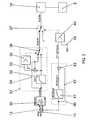
- Fig. 3 shows a schematic of the control unit 12, these being hardware units can consist of or the individual steps are from a processor processed repetitively.
- This signal enters the opening delay group 31.
- a first delay element 32 its Function is denoted by EV_F, converted into a delayed signal and with a negative sign to a first summer 33.
- the difference is the delayed one Signal and the in the bypass line 34 listed undelayed formed static signal.
- the first comparator 35 this is compared with the size 0. If the difference is greater than 0, that is Exhaust gas recirculation valve 16 is to be opened, provides a first switch 36th the connection via the first delay element 32 ago. Otherwise the comparator 35 brings the first switch 36 in the illustrated position, in which the stationary setpoint signal EVSTAT the delay element bypasses and taken as a dynamic setpoint signal EVDYN becomes. This ensures that the first delay element 32 only when opening the exhaust gas recirculation valve 5 comes into effect, not but when closing.
- the signal BETACAL branches A branch goes over second delay element 41 and the other branch unchanged via a second bypass line 42 to a second summation 43. Die Difference from an instantaneous signal and the same signal, but delayed, corresponds to a filtered differential derivative of first order. In other words, the difference between the signal BETACAL and BETACALF is a differential.
- the resulting filtered differential signal DT1_BETACAL is supplied to a second comparator 44 and there compared with a threshold SW. If the signal DT1_BETACAL is greater than the threshold SW, then the second comparator, the second switch 37 and switches this in the Position in which the position setpoint for the servo 16 is zero.
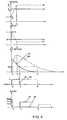
- this curve intersects threshold SW, causing switch 37 to move to the 0 position, curve 63, and also the desired valve position EVCOM returns to zero.
- a slight decrease in the curve 54 before the time T2 is not visible in Figure 4.
- the sinking differential curve 62 again intersects the horizontal value corresponding to the threshold value SW at time t 4 .
- the second switch 37 is returned to the position EVDYN according to curve 63 at the time t 4 and, accordingly, according to curve 64, the full-valve position EVCOM corresponding to the new operating state of 10% is reached.
- the corresponding operating point is indicated in FIG. 2 and designated by 24.
Landscapes
- Engineering & Computer Science (AREA)
- Chemical & Material Sciences (AREA)
- Combustion & Propulsion (AREA)
- Mechanical Engineering (AREA)
- General Engineering & Computer Science (AREA)
- Exhaust-Gas Circulating Devices (AREA)
Description
- Fig. 1:
- Das Schema einer für die Anwendung des erfindungsgemäßen Verfahrens geeigneten Verbrennungskraftmaschine,
- Fig. 2:
- Ein Beispiel eines Kennfeldes für die Abgas-Rückführrate,
- Fig. 3:
- Ein Schaltschema der erfindungsgemäßen Steuerungsvorrichtung,
- Fig. 4:
- Ein Zeitschaubild zum erfindungsgemäßen Verfahren.
Claims (5)
- Verfahren zur Steuerung des Abgasrückführventiles einer luftverdichtenden Verbrennungskraftmaschine zur Verhinderung des Rauchstoßes durch Reduzierung der Abgasrückführrate bei steigender Belastung, bei welchem Verfahren von der momentanen Motordrehzahl und von der momentanen Lastanforderung ausgegangen wird, bestehend aus folgenden Schritten:a) aus der momentanen Motordrehzahl [RPM] und der momentanen Lastanforderung [BETACAL] wird anhand einer Tabelle [TBEGRV] eine stationäre Sollstellung [EVSTAT] des Abgasrückführventiles ermittelt,b) aus dieser stationären Sollstellung [EVSTAT] wird zeitverzögernd eine dynamische Sollstellung [EVDYN] gebildet,c) aus der momentanen Lastanforderung [BETACAL] wird eine deren Änderungsgeschwindigkeit entsprechende Schaltfunktion [DT1_BETACAL] ermittelt und mit einem Schwellenwert [SW] verglichen,d) solange der Funktionswert der Schaltfunktion [DT1_BETACAL] über dem Schwellenwert [SW] liegt, wird die zeitverzögerte dynamische Sollstellung [EVDYN] unterdrückt und statt dessen der Wert Null gesetzt,e) wenn der Funktionswert der Schaltfunktion [DT1_BETACAL] unter dem Schwellenwert [SW] liegt, nimmt das Abgasrückführventil die dynamische Sollstellung [EVDYN] ein.
- Verfahren nach Anspruch 1, dadurch gekennzeichnet, dass die der Änderungsgeschwindigkeit der momentanen Lastanforderung [BETACAL] entsprechende Schaltfunktion [DT1_BETACAL] die repetitiv berechnete Differenz aus der momentanen Lastanforderung [BETACAL] und der gefilterten momentanen Lastanforderung [BETACALF] ist.
- Vorrichtung zur Steuerung des Abgasrückführventiles einer luftverdichtenden Verbrennungskraftmaschine, die einen Sensor (6) zur Ermittlung eines der Motordrehzahl entsprechenden Signales [RPM], eine Einheit (8) zur Ermittlung eines der Lastanforderung entsprechenden Signales [BETACAL], eine Steuereinheit (12) und eine Servoeinheit (16) zur Betätigung des Abgasrückführventiles (5) umfasst, wobei die Steuereinheit aus dem der Motordrehzahl entsprechenden Signale [RPM] und dem der Lastanforderung entsprechenden Signal [BETACAL] unter Benutzung einer Tabelle [TBEGRV] ein Sollstellungssignal [EVCOM] für die Servoeinheit (16) erzeugt, dadurch gekennzeichnet, dass die Steuereinheit enthält:a) ein erstes Verzögerungsglied (32) mit einem ersten Komparator (35) und einem ersten Schalter (36), wobei das Verzögerungsglied aus dem statischen Sollstellungssignal [EVSTAT] ein dynamisches Sollstellungssignal [EVDYN] bildet und der Komparator (35) die Verzögerung beim Schließen des Abgasrückführventiles (5) unterdrückt, indem er den ersten Schalter (36) betätigt,b) einem Differenzierglied (40) mit einem nachgeordneten zweiten Komparator (44), wobei das Differenzierglied das der Lastanforderung entsprechende Signal [BETACAL] differenziert und es der zweite Komparator (44) mit einem Schwellenwert [SW] vergleicht,c) einem zweiten Schalter (37), der das Sollstellungssignal [EVCOM] gleich Null setzt, wenn im zweiten Komparator (44) der Schwellenwert [SW] überschritten wird.
- Vorrichtung zur Steuerung des Abgasrückführventiles nach Anspruch 3, dadurch gekennzeichnet, dass die Zeitkonstante des Differenziergliedes (41) größer als die Zeitkonstante des Verzögerungsliedes (32) ist.
- Vorrichtung zur Steuerung des Abgasrückführventiles nach Anspruch 3, dadurch gekennzeichnet, dass der Schwellenwert [SW] motor- und fahrzeugspezifisch gewählt wird.
Priority Applications (1)
| Application Number | Priority Date | Filing Date | Title |
|---|---|---|---|
| AT01890238T ATE288541T1 (de) | 2000-08-18 | 2001-08-20 | Verfahren und vorrichtung zur steuerung der abgasrückführung einer luftverdichtenden verbrennungskraftmaschine |
Applications Claiming Priority (2)
| Application Number | Priority Date | Filing Date | Title |
|---|---|---|---|
| AT0060100U AT5938U1 (de) | 2000-08-18 | 2000-08-18 | Verfahren und vorrichtung zur steuerung der abgasrückführung einer luftverdichtenden verbrennungskraftmaschine |
| AT6012000U | 2000-08-18 |
Publications (3)
| Publication Number | Publication Date |
|---|---|
| EP1180589A2 EP1180589A2 (de) | 2002-02-20 |
| EP1180589A3 EP1180589A3 (de) | 2003-04-23 |
| EP1180589B1 true EP1180589B1 (de) | 2005-02-02 |
Family
ID=3494884
Family Applications (1)
| Application Number | Title | Priority Date | Filing Date |
|---|---|---|---|
| EP01890238A Expired - Lifetime EP1180589B1 (de) | 2000-08-18 | 2001-08-20 | Verfahren und Vorrichtung zur Steuerung der Abgasrückführung einer Luftverdichtenden Verbrennungskraftmaschine |
Country Status (3)
| Country | Link |
|---|---|
| EP (1) | EP1180589B1 (de) |
| AT (2) | AT5938U1 (de) |
| DE (1) | DE50105231D1 (de) |
Families Citing this family (4)
| Publication number | Priority date | Publication date | Assignee | Title |
|---|---|---|---|---|
| JP4161849B2 (ja) * | 2003-08-25 | 2008-10-08 | 株式会社デンソー | 内燃機関の制御装置 |
| US7398773B2 (en) * | 2003-11-12 | 2008-07-15 | Mack Trucks, Inc. | EGR recovery system and method |
| DE10360218B4 (de) * | 2003-12-20 | 2016-11-24 | Robert Bosch Gmbh | Abgasrückführverfahren zum Einstellen einer Abgasrückführung einer Brennkraftmaschine |
| DE102015214034B4 (de) * | 2015-07-24 | 2019-08-01 | Volkswagen Aktiengesellschaft | Steuern einer Verbrennungskraftmaschine im transienten Betrieb |
Family Cites Families (5)
| Publication number | Priority date | Publication date | Assignee | Title |
|---|---|---|---|---|
| US3915134A (en) * | 1974-03-04 | 1975-10-28 | Dana Corp | Exhaust gas recirculation system for internal combustion engines |
| DE3801296C1 (en) * | 1988-01-19 | 1988-07-28 | Daimler-Benz Ag, 7000 Stuttgart, De | Exhaust gas recirculation device in a diesel internal combustion engine |
| JP3070334B2 (ja) * | 1993-04-16 | 2000-07-31 | トヨタ自動車株式会社 | ディーゼル機関の燃料噴射制御装置 |
| DE19615545C1 (de) * | 1996-04-19 | 1997-06-12 | Daimler Benz Ag | Einrichtung zur Dieselmotorbetriebsregelung mit Abgasrückführung und Ansaugluftdrosselung |
| US6128902A (en) * | 1999-01-26 | 2000-10-10 | Ford Global Technologies, Inc. | Control method and apparatus for turbocharged diesel engines having exhaust gas recirculation |
-
2000
- 2000-08-18 AT AT0060100U patent/AT5938U1/de not_active IP Right Cessation
-
2001
- 2001-08-20 EP EP01890238A patent/EP1180589B1/de not_active Expired - Lifetime
- 2001-08-20 DE DE50105231T patent/DE50105231D1/de not_active Expired - Fee Related
- 2001-08-20 AT AT01890238T patent/ATE288541T1/de not_active IP Right Cessation
Also Published As
| Publication number | Publication date |
|---|---|
| ATE288541T1 (de) | 2005-02-15 |
| EP1180589A3 (de) | 2003-04-23 |
| EP1180589A2 (de) | 2002-02-20 |
| AT5938U1 (de) | 2003-01-27 |
| DE50105231D1 (de) | 2005-03-10 |
Similar Documents
| Publication | Publication Date | Title |
|---|---|---|
| EP0937198B1 (de) | Verfahren und vorrichtung zur steuerung einer antriebseinheit eines fahrzeugs | |
| EP1576285B1 (de) | Verfahren zur zündwinkelbestimmung | |
| DE3313036C2 (de) | Vorrichtung zur Verhinderung des klopfenden Betriebs bei Brennkraftmaschinen | |
| DE19756053B4 (de) | Drosselklappensteuervorrichtung | |
| DE3028940A1 (de) | Regelvorrichtung fuer eine verbrennungskraftmaschine | |
| DE3714151A1 (de) | Steuereinrichtung fuer die drosselklappe eines verbrennungsmotors | |
| EP1317613A1 (de) | Verfahren zum betreiben einer brennkraftmaschine und entsprechende vorrichtung | |
| DE3102627A1 (de) | Vorrichtung zur verstellung des zuendzeitpunktes fuer einen verbrennungsmotor mit fremdzuendung | |
| EP0631897A1 (de) | Verfahren und Vorrichtung zur Steuerung einer Antreibseinheit eines Fahreugs | |
| DE4112848C2 (de) | System zur Regelung der Leerlaufdrehzahl einer Brennkraftmaschine | |
| EP1613852B1 (de) | Verfahren zum betreiben eines verbrennungsmotors mit einer drehmoment berwachung | |
| EP1005609B1 (de) | Verfahren zur steuerung der abgasrückführung bei einer brennkraftmaschine | |
| DE19534633A1 (de) | Verfahren und Vorrichtung zur Steuerung einer Antriebseinheit eines Fahrzeugs | |
| EP1078163B1 (de) | Verfahren zur zündsteuerung | |
| DE3439927C2 (de) | ||
| DE4417802B4 (de) | Vorrichtung zur Regelung der Motorleistung oder der Fahrgeschwindigkeit eines Fahrzeugs | |
| EP0077997B1 (de) | Verfahren und Vorrichtung zur Regelung der Drehzahl einer Brennkraftmaschine | |
| WO1989005905A1 (fr) | Procede et agencement de regulation du dosage d'air dans des moteurs a combustion interne, notamment au ralenti et en deceleration | |
| WO1991009220A1 (de) | System zur regelung eines betriebsparameters einer brennkraftmaschine eines kraftfahrzeugs | |
| EP0205916A2 (de) | Verfahren zur Steuerung und/oder Regelung von Betriebskenngrössen einer Brennkraftmaschine | |
| EP0460126B1 (de) | System zur elektronischen steuerung und/oder regelung der leistung einer brennkraftmaschine eines kraftfahrzeugs | |
| EP1830049A1 (de) | Verfahren und Steuergerät zur Einstellung eines Turbinenströmungsquerschnitts eines Turboladers | |
| AT5938U1 (de) | Verfahren und vorrichtung zur steuerung der abgasrückführung einer luftverdichtenden verbrennungskraftmaschine | |
| DE19547716B4 (de) | Verfahren und Vorrichtung zum Regeln bzw. Begrenzen der Geschwindigkeit eines Fahrzeugs | |
| WO1999049194A2 (de) | Verfahren zum betreiben einer brennkraftmaschine |
Legal Events
| Date | Code | Title | Description |
|---|---|---|---|
| PUAI | Public reference made under article 153(3) epc to a published international application that has entered the european phase |
Free format text: ORIGINAL CODE: 0009012 |
|
| AK | Designated contracting states |
Kind code of ref document: A2 Designated state(s): AT BE CH CY DE DK ES FI FR GB GR IE IT LI LU MC NL PT SE TR |
|
| AX | Request for extension of the european patent |
Free format text: AL;LT;LV;MK;RO;SI |
|
| PUAL | Search report despatched |
Free format text: ORIGINAL CODE: 0009013 |
|
| AK | Designated contracting states |
Designated state(s): AT BE CH CY DE DK ES FI FR GB GR IE IT LI LU MC NL PT SE TR |
|
| AX | Request for extension of the european patent |
Extension state: AL LT LV MK RO SI |
|
| 17P | Request for examination filed |
Effective date: 20030404 |
|
| 17Q | First examination report despatched |
Effective date: 20030528 |
|
| RAP1 | Party data changed (applicant data changed or rights of an application transferred) |
Owner name: MAGNA STEYR FAHRZEUGTECHNIK AG & CO KG |
|
| AKX | Designation fees paid |
Designated state(s): AT DE FR GB |
|
| GRAP | Despatch of communication of intention to grant a patent |
Free format text: ORIGINAL CODE: EPIDOSNIGR1 |
|
| GRAS | Grant fee paid |
Free format text: ORIGINAL CODE: EPIDOSNIGR3 |
|
| GRAA | (expected) grant |
Free format text: ORIGINAL CODE: 0009210 |
|
| RAP1 | Party data changed (applicant data changed or rights of an application transferred) |
Owner name: ENGINEERING CENTER STEYR GMBH & CO KG |
|
| AK | Designated contracting states |
Kind code of ref document: B1 Designated state(s): AT DE FR GB |
|
| REG | Reference to a national code |
Ref country code: GB Ref legal event code: FG4D Free format text: NOT ENGLISH |
|
| REG | Reference to a national code |
Ref country code: IE Ref legal event code: FG4D Free format text: GERMAN |
|
| REF | Corresponds to: |
Ref document number: 50105231 Country of ref document: DE Date of ref document: 20050310 Kind code of ref document: P |
|
| GBT | Gb: translation of ep patent filed (gb section 77(6)(a)/1977) |
Effective date: 20050517 |
|
| PLBE | No opposition filed within time limit |
Free format text: ORIGINAL CODE: 0009261 |
|
| STAA | Information on the status of an ep patent application or granted ep patent |
Free format text: STATUS: NO OPPOSITION FILED WITHIN TIME LIMIT |
|
| 26N | No opposition filed |
Effective date: 20051103 |
|
| ET | Fr: translation filed | ||
| PGFP | Annual fee paid to national office [announced via postgrant information from national office to epo] |
Ref country code: DE Payment date: 20070822 Year of fee payment: 7 |
|
| PGFP | Annual fee paid to national office [announced via postgrant information from national office to epo] |
Ref country code: AT Payment date: 20070816 Year of fee payment: 7 |
|
| PGFP | Annual fee paid to national office [announced via postgrant information from national office to epo] |
Ref country code: GB Payment date: 20070823 Year of fee payment: 7 |
|
| PGFP | Annual fee paid to national office [announced via postgrant information from national office to epo] |
Ref country code: FR Payment date: 20070812 Year of fee payment: 7 |
|
| GBPC | Gb: european patent ceased through non-payment of renewal fee |
Effective date: 20080820 |
|
| PG25 | Lapsed in a contracting state [announced via postgrant information from national office to epo] |
Ref country code: AT Free format text: LAPSE BECAUSE OF NON-PAYMENT OF DUE FEES Effective date: 20080820 |
|
| REG | Reference to a national code |
Ref country code: FR Ref legal event code: ST Effective date: 20090430 |
|
| PG25 | Lapsed in a contracting state [announced via postgrant information from national office to epo] |
Ref country code: DE Free format text: LAPSE BECAUSE OF NON-PAYMENT OF DUE FEES Effective date: 20090303 Ref country code: FR Free format text: LAPSE BECAUSE OF NON-PAYMENT OF DUE FEES Effective date: 20080901 |
|
| PG25 | Lapsed in a contracting state [announced via postgrant information from national office to epo] |
Ref country code: GB Free format text: LAPSE BECAUSE OF NON-PAYMENT OF DUE FEES Effective date: 20080820 |