EP1180490A2 - Load moment indicator of crane - Google Patents
Load moment indicator of crane Download PDFInfo
- Publication number
- EP1180490A2 EP1180490A2 EP01107379A EP01107379A EP1180490A2 EP 1180490 A2 EP1180490 A2 EP 1180490A2 EP 01107379 A EP01107379 A EP 01107379A EP 01107379 A EP01107379 A EP 01107379A EP 1180490 A2 EP1180490 A2 EP 1180490A2
- Authority
- EP
- European Patent Office
- Prior art keywords
- load
- hoist
- auxiliary
- main
- value
- Prior art date
- Legal status (The legal status is an assumption and is not a legal conclusion. Google has not performed a legal analysis and makes no representation as to the accuracy of the status listed.)
- Granted
Links
Images




Classifications
-
- B—PERFORMING OPERATIONS; TRANSPORTING
- B66—HOISTING; LIFTING; HAULING
- B66C—CRANES; LOAD-ENGAGING ELEMENTS OR DEVICES FOR CRANES, CAPSTANS, WINCHES, OR TACKLES
- B66C23/00—Cranes comprising essentially a beam, boom, or triangular structure acting as a cantilever and mounted for translatory of swinging movements in vertical or horizontal planes or a combination of such movements, e.g. jib-cranes, derricks, tower cranes
- B66C23/88—Safety gear
- B66C23/90—Devices for indicating or limiting lifting moment
- B66C23/905—Devices for indicating or limiting lifting moment electrical
Definitions
- the present invention relates to a load moment indicator of a crane provided with a suspension means.
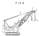
- reference numeral 1 designates a self-traveling type (in the figure, a crawler traveling type is shown) crane body 1.
- a boom 2 is mounted on the crane body 1 to so as to be hoisted and lowered.
- An auxiliary sheave bracket 4 with an auxiliary sheave 3 is mounted, as an auxiliary suspending arm, at the extreme end of the boom 2.
- a boom raising and lowering winch 5 On the crane body 1 are mounted a boom raising and lowering winch 5, a main winch 6 and an auxiliary winch 7.
- the boom 2 is driven to be hoisted and lowered by the boom raising and lowering winch 5 through a boom reeving rope 8 and a boom guyline 9.
- a main hoist rope 10 drawn out of the main winch 6 is suspended from the extreme end of the boom to suspend a main hook 11 in the form of being suspended by many ropes.
- the main hoist means constituted as described above, the main winding and hoisting work for raising and lowering mainly a very heavy cargo at a low speed takes place.
- an auxiliary hoist rope 12 drawn out of the auxiliary winch 7 is suspended from the auxiliary sheave bracket 4 to suspend an auxiliary hook 13 permanently.
- the main winding and suspending work and the auxiliary winding and suspending work are sometimes carried out simultaneously.
- the overload preventive method of a crane provided with two kinds of suspension means of the main side and the auxiliary side as described above is disclosed, for example, in Japanese Patent Application Laid-Open No. Hei 11-246178 Publication.
- Tension of both the main and auxiliary hoist ropes 10 and 12 and tension of the boom guyline 9 are respectively detected by a detector to calculate a main hoist load, an auxiliary hoist load, and the whole hoist load. Subsequently, when the hoist loads, and at least one of load factors obtained from the rated loads preset reach a fixed value, an automatic stop valve is operated to automatically stop the crane operation.
- the rated load termed herein is the maximum hoist load obtained on the basis of the stability of a crane and the strength of constitutional members (normally, the rupture strength of a rope), which load is calculated every work radius in advance and stored in a memory.
- the overload preventive method is basically the same as that described above.
- the load value capable of being suspended by the own side by the hoist loads in other sides ought to be varied.
- the respective rated load is set as a fixed value without taking it into consideration, and therefore, there poses a problem that an operator cannot grasp the tolerance as to how much ton, resulting in an obstacle of work.
- the load moment indicator of a crane according to the present invention comprises:
- the first hoist means corresponds to a main hoist means.
- the first winch, the first rope, and the first hook correspond to a main winch, a main hoist rope, and a main hook, respectively.
- the second hoist means, the second winch, the suspending arm, the second rope correspond to an auxiliary hoist means, an auxiliary winch, an auxiliary suspending arm, an auxiliary hoist rope, and an auxiliary hook, respectively.
- the rated loads be constituted by the following:
- the rated load of own side can be varied according to the hoist load of other sides. Therefore, the maximum hoist load that can be suspended by both the systems actually irrespective of the single hoisting work time and the simultaneous hoisting work time of both systems can be determined as the rated load.
- both the main side and auxiliary side are set on the basis of the same base (for example, the crane stability), in both the systems, the suspending weight of other sides may be taken (subtracted) as the load component of own side on the basis of a base of own side to thereby obtain the rated load.
- the present load moment indicator is constituted by a calculation processing section 14 as a calculation means, an automatic stop valve (a solenoid valve) 15, a display section 16, and a group of detectors 20 to 23.
- the calculation processing section 14 comprises a memory section 17, a load factor calculation section 18, and a stop processing section 19.
- Respective detectors 20 to 23 are provided; i.e., a boom angle detector 20 for detecting a boom angle, a guyline tension detector 21 as a whole hoist load detecting means for detecting a tension (whole hoist load) of the boom guyline 9 shown in FIG.6, a main hoist rope tension detector 22 as a main winding hoist load detecting means for detecting a tension (main side hoist load) of the main hoist rope 10, and a auxiliary hoist rope tension detector 23 as a auxiliary winding hoist load detecting means for detecting a tension (auxiliary side hoist load) of the auxiliary hoist rope 12. Detection values obtained by each of detectors 20 to 23 are input to the load factor calculation section 18.
- the load factor calculation section 18 comprises a whole load factor calculation section 24, a main side load factor calculation section 25, and an auxiliary side load factor calculation section 26.
- a stop signal is then sent to the automatic stop valve (solenoid valve) 15, and the crane operation automatically stops.
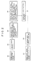
- the processing contents of the load factor calculation section 18 will be described in detail with reference to FIGS. 1 and 2.
- a main side hoist load WM is obtained from a detected value of a main hoist rope tension by the main hoist rope tension detector 22 (Steps S1, S2).
- the work radius is obtained from the present boom angle detected by the boom angle detector 20 (Steps S3, S4).
- a reference value WRM of the rated load stored in advance every work radius in the memory section 17 is read from the work radius (Step S5).
- the reference value WRM is set as the maximum load value that can be suspended singly by the main winding within a fixed stability with a stability (lowering-down prevention) of a crane as a base.
- an auxiliary side hoist load value WA obtained on the basis of the detected value from the auxiliary hoist rope tension detector 23 is converted into a load component of the main side.
- the converted value from the reference value WRM of the main side is subtracted to calculate rated load value WRM1 which is a load value capable of being suspended singly by the main side within the stability at present (Step S6).
- the present load factor is then obtained from the rated load value WRM obtained in Step S6 and the main side hoist load value WM (Step S7).
- a stop signal is sent to the automatic stop valve 15 through the stop processing section 19 as described previously.
- Step S6 which is one of characteristics of the load moment indicator, will be described in more detail.
- the main hook 11 side is used in the form of multi-suspension
- the auxiliary hook 13 side is used in the form of permanent suspension.
- the rated load of the main side is usually determined on the basis of the stability of a crane since there is a high possibility that the lowering down of a crane occurs prior to the rupture of the main hoist rope 10.
- the auxiliary side employs a single suspension so that the rupture of the auxiliary hoist rope 12 comes into question, the rated load is determined on the basis of the rope rupture strength.
- the rated load value of the main side at a work radius is 40t determined from the stability of a crane, and the rated load value of the auxiliary side is 10t determined from the rupture strength of a rope.
- main side reference value aux side reference value a main winding single hoisting work 40t ⁇ b aux. winding single hoisting work ⁇ 10t c main winding simultaneous work 40 ⁇ 20t 0 ⁇ 10t
- a cargo of 40t and a cargo of 10t can be suspended in the main winding and auxiliary winding, respectively, as shown in (a) and (b) of Table 1.
- a load that can be suspended in the main side gradually reduces from 40t to 20t as the cargo in the auxiliary side increase from 0t to 10t.
- the hoist load in the main side is not more than 20t
- 10t at the maximum can be suspended in the auxiliary side.
- the load that can be suspended in the auxiliary side gradually reduces from 10t to 0t as the hoist load in the main side increases from 20t to 40t.
- ⁇ M and ⁇ A are stored in advance in the memory 17.
- WRM is a reference value of the rated load that can be suspended in the case of the main side single stored in the memory 17.
- the value obtained by converting the hoist load value WA in the auxiliary side into the load component on the main side side is subtracted to obtain the rated load value WRM in the main side that can be suspended actually in consideration of the present auxiliary side load value.
- WRM1 WRM results.
- a cargo of 20t can be suspended in the main side in the state that only 10t is suspended in the auxiliary side. Accordingly, there can make the most of the suspending ability peculiar to the crane at the maximum.
- a tolerant load of the other side (in the above example, the main side) is converted into a load component in own side (the auxiliary system) on the basis of a base (the crane stability) of a reference value in the other side (same as above).
- This converted value is compared with the reference value of own side (auxiliary system) to select the lower value as the rated load, whereby enabling to make the most of the suspending ability of both the systems at the maximum.
- a tolerant load (a load that can be still suspended in the main side) part of the main side is converted into the load component WRA1 of the auxiliary side (a load value that can be suspended in the auxiliary side with respect to the main side load in terms of the stability) on the basis of the stability of a crane which is a base of the rated load in the main side.
- a load that can be suspended at present taking the hoist load in the other side into consideration is determined as a rated load. With this, there can make the most of the suspending ability of both the systems at the maximum.
- the first calculation method is normally used which uses detected values obtained by three tension detectors 21, 22, and 23 as described above. However, it is constituted so that where an abnormal condition should occur in one of these detectors, the method is switched automatically to a second calculation method in which the abnormal condition is judged by a signal of a detector (for example, it can be judged by the lowering of an output voltage of a detector), and the load is computed on the basis of detected values obtained by the remaining two detectors.
- the method is automatically switched to the calculation method corresponding thereto, thus enabling execution of the load computation without any trouble.
- that effect may be displayed on the display section 16 for an operator.
- one of three detectors 21, 22, and 23 becomes disabled for detection due to the work conditions (such as a difference in crane work and clamshell work, or a difference in the way of stretching a rope with respect to a hook), or a case where one of the detectors is not used intentionally for the reason such as reduction in display (or calculation) errors.
- the switching means 27 may be provided as indicated by the dash-dotted contour lines in FIG. 1 so as to switch the calculation method between the first calculation method and the second calculation method.
- the load calculation is carried out on the basis of the detected values of the remaining two detecting means. Therefore, the load calculation is carried out without any trouble according to the work conditions including abnormality of detection. Particularly, when one detecting means is abnormal, the calculation section judges this abnormality to automatically switch the calculation methods. Therefore, no erroneous calculation caused by the forgetting of switching or the switching mistake occurs.
- the work in the crane work includes three kinds of work; i.e., the main winding hoisting work by the main hoist means, the auxiliary winding hoisting work by the auxiliary hoist means, and the simultaneous hoisting work for carrying out them simultaneously.
- a signal representative of the kinds of these work, and a work-state signal such as a signal in connection with the present load and load factor are output from the calculation processing section 14 (load factor calculation section 18) to the display section 16.
- the kind of work being now carried out and the contents of work are displayed by the display section 16 along with other necessary data on the basis of the aforementioned signals.
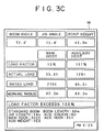
- FIGS. 3A to 3C One example of the displayed contents is shown in FIGS. 3A to 3C.
- FIGS. 3A, 3B, and 3C show the displayed contents of the main winding hoisting work time, the auxiliary hoisting work time, and the simultaneous hoisting work time, respectively.
- Characters “main hoist”, “auxiliary hoist”, and “simultaneous hoist” which show the main winding, auxiliary winding, and simultaneous winding, respectively, are displayed on a monitor screen.
- both “main hoist” and “auxiliary hoist” which mean “simultaneous hoist” are displayed (FIG. 3C).
- “simultaneous hoist” may be displayed.
- the display of "simultaneous hoist” is called hereinafter.
- the work contents of the load factor, actual load, rated load, and work radius are displayed in numerical value.
- work data such as boom angle, jib angle, point height (height of a boom point) and so on are displayed in numerical value.
- the calculation processing section 14 automatically switches the display of work state by the display section 16 on the basis of a detector signal.
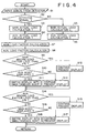
- a detector signal is input (Step S1). Judgment is made whether or not the tension detectors 21, 22, and 23 for the guyline, main hoist rope, and auxiliary hoist rope are normal (abnormal) on the basis of the detector signal (Step S2).
- the main winding suspension load in the drawing, the main actual load is described
- the auxiliary suspension load also, in the drawing, the auxiliary actual load
- the main winding suspension load and the auxiliary suspension load are calculated by the second calculation method (Steps S5 and S6).
- Step S7 and S8 both load factors for the main winding and the auxiliary winding are obtained-on the basis of both suspension loads for the main winding and auxiliary winding.
- Step S9 judgment is made whether or not the main winding load factor is less than a value (X%) preset as numerical value representative of the absence of load. If NO (main winding load is present) is judged, judgment is made in Step S10, whether or not the present display is "auxiliary hoist". If YES ("auxiliary hoist"), the display is switched to "Simultaneous suspension" in Step 11.
- Step S9 NO (main winding load is not present) is judged in Step S9
- the present display one of "main hoist", “auxiliary hoist” and “simultaneous hoist" is continued in Step S12.
- the auxiliary winding suspension display is not present (“main hoist” or “simultaneous hoist")
- the present display (“main hoist” or "hoist”) is continued in Step S13.
- Step S14 judgment is made whether or not the auxiliary winding load factor is less than X (%) similarly to the case of the main winding load factor in Step S9. If judgment is made of YES (auxiliary winding load is not present), the present display (one of "main hoist", “auxiliary hoist” and “simultaneous hoist” is continued in Step S15.
- Step S14 if NO (auxiliary winding load is present) is judged in Step S14, the step proceeds to Step S16, in which judgment is made whether or not the present display is "main hoist". If NO, the present display ("auxiliary hoist" or “simultaneous hoist") is continued in Step 17.
- Step 16 the display is switched to "simultaneous hoist" in Step 18.
- the display in the display section 16 can be adjusted to the present work state. Therefore, even where the work state is often changed, or where the work continues for a period of time, the work state can be recognized clearly by an operator. Further, the display effect can be improved by pressing the display to a necessary display. Thereby, the safety can be further improved.
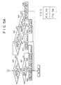
- FIG. 5 shows a partial modification of the flow shown in FIG. 4.
- the flow of FIG. 5 employs a constitution of returning to the original display at X - Y% (clearly smaller value than X) in order to stabilize the display with a moderate hysteresis.
- Step S1 to Step S11 employ the same procedure as the case of FIG. 4; in Step S9, if YES (the main winding load factor is less than X%), whether or not the main winding load factor is X - Y% is further judged in Step S12. If NO, the present display is continued (Step S13), and if YES (clearly smaller than X), whether or not the auxiliary load factor is X - Y% is judged in Step S14.
- Step S15 If NO (auxiliary winding load is present), the display is switched to "auxiliary hoist" in Step S15. If YES (auxiliary winding load is not present), the display is switched to "simultaneous hoist" in Step S16. If NO in Step S10, the present display is continued in Step S17.
- the kind of work being carried out at present and the work contents can be displayed from the main hoisting work, auxiliary hoisting work, and simultaneous hoisting work. Therefore, even where the work state is often changed, or where the work continues for a long period of time, the present work state can be recognized clearly by an operator. Further, the display effect can be improved by pressing the display to a necessary display. Thereby, the safety can be further improved.
- the present invention can be applied to not only the lattice boom type crane illustrated in the above embodiments, but also a crane using a box-shaped expansion boom (in which case, the length of a boom is changed, whereby the work radius is changed).
- An load moment indicator in a crane provided with hoist means of a main side and an auxiliary side, including a calculator in which a reference value if a rated load determined by the stability of a crane or the like is preset, a hoist load of the other side is converted into a load component of own side, and the converted value is subtracted from a reference value of own side to thereby obtain a rated load of own side, or in which a tolerant load that can be suspended by the other side is converted into a load component of own side on the basis of a base of a reference value of the other side, and the converted value is compared with the reference value of own side to select a lower value.
Landscapes
- Engineering & Computer Science (AREA)
- Mechanical Engineering (AREA)
- Jib Cranes (AREA)
Abstract
Description
| main side reference value | aux. side reference value | ||
| a | main winding single hoisting work | 40t | ― |
| b | aux. winding single hoisting work | ― | 10t |
| c | main winding simultaneous work | 40~20t | 0~10t |
WRA1 > WRA → WRA2 = WRA
- 15
- AUTOMATIC STOP VALVE
- 16
- DISPLAY SECTION
- 17
- MEMORY SECTION
- 19
- TOP PROCESSING SECTION
- 20
- BOOM ANGLE DETECTOR
- 21
- GUYLINE TENSION DETECTOR
- 22
- MAIN HOIST ROPE TENSION DETECTOR
- 23
- AUXILIARY HOIST ROPE TENSION DETECTOR
- 24
- WHOLE LOAD FACTOR CALCULATING SECTION
- 25
- MAIN SIDE LOAD FACTOR CALCULATING SECTION
- 26
- AUXILIARY SIDE LOAD FACTOR CALCULATING SECTION
- 27
- SWITCHING MEANS
- S1
- MAIN HOIST ROPE TENSION DETECTION VALUE
- S2
- OBTAIN MAIN HOIST LOAD WM
- S3
- BOOM ANGLE DETECTION VALUE
- S4
- OBTAIN WORK RADIUS
- S5
- READ MAIN SIDE REFERENCE VALUE WRM CORRESPONDING TO WORK RADIUS FROM MEMORY SECTION
- S6
- OBTAIN MAIN SIDE RATED LOAD WRM1 BY CONVERTING AUXILIARY HOIST LOAD VALUE WA INTO MAIN SIDE LOAD COMPONENT TO SUBTRACT IT FROM WRM
- S7
- MAIN SIDE LOAD FACTOR = WM/WRM1
BOOM ANGLE POINT HEIGHT
MAIN HOIST
LOAD FACTOR
ACTUAL LOAD
RATED LOAD
WORK RADIUS
STANDARD BOOM BOOM LENGTH: JIB LENGTH:
AUX. SHEAVE: NO MAIN HOOK: AUX. HOOK:
ADD WEIGHT: YES
BOOM ANGLE
AUX. HOIST
LOAD FACTOR
ACTUAL LOAD
RATED LOAD
WORK RADIUS
STANDARD BOOM BOOM LENGTH: JIB LENGTH:
AUX. SHEAVE: NO MAIN HOOK: AUX. HOOK:
ADD WEIGHT: YES
BOOM ANGLE JIB ANGLE POINT HEIGHT
MAIN HOIST AUX. HOIST
LOAD FACTOR
ACTUAL LOAD
RATED LOAD
WORK RADIUS
LOAD FACTOR EXCEEDS 100%
STANDARD BOOM BOOM LENGTH: JIB LENGTH:
AUX. SHEAVE: NO MAIN HOOK: AUX. HOOK:
ADD WEIGHT: YES
- S1
- INPUT SIGNAL FROM DETECTOR
- S2
- DETECTOR NORMAL?
- S3
- MAIN ACTUAL LOAD CALCULATION
- S4
- AUX.
ACTUAL LOAD CALCULATION 1 - S5
- MAIN
ACTUAL LOAD CALCULATION 2 - S6
- AUX.
ACTUAL LOAD CALCULATION 2 - S7
- MAIN LOAD FACTOR CALCULATION
- S8
- AUX. LOAD FACTOR CALCULATION
- S9
- MAIN WINDING LOAD FACTOR LESS THAN X%?
- S10
- AUX. HOIST DISPLAYED?
- S11
- SWITCH DISPLAY INTO SIMULTANEOUS HOIST
- S12
- CONTINUE PRESENT DISPLAY
- S13
- CONTINUE PRESENT DISPLAY
- S14
- AUX. WINDING LOAD FACTOR LESS THAN X%?
- S15
- CONTINUE PRESENT DISPLAY
- S16
- MAIN HOIST DISPLAYED?
- S17
- CONTINUE PRESENT DISPLAY
- S18
- SWITCH DISPLAY INTO SIMULTANEOUS HOIST
- S1
- INPUT SIGNAL FROM DETECTOR
- S2
- DETECTOR NORMAL?
- S3
- MAIN
ACTUAL LOAD CALCULATION 1 - S4
- AUX.
ACTUAL LOAD CALCULATION 1 - S5
- MAIN
ACTUAL LOAD CALCULATION 2 - S6
- AUX.
ACTUAL LOAD CALCULATION 2 - S7
- MAIN LOAD FACTOR CALCULATION
- S8
- AUX. LOAD FACTOR CALCULATION
- S9
- MAIN WINDING LOAD FACTOR LESS THAN X%?
- S10
- AUX. HOIST DISPLAYED?
- S11
- SWITCH DISPLAY INTO SIMULTANEOUS HOIST
- S12
- MAIN WINDING LOAD FACTOR LESS THAN X - Y%?
- S13
- CONTINUE PRESENT DISPLAY
- S14
- AUX. WINDING LOAD FACTOR LESS THAN X - Y%?
- S15
- SWITCH DISPLAY INTO AUX. HOIST
- S16
- SWITCH DISPLAY INTO SIMULTANEOUS HOIST
- S17
- CONTINUE PRESENT DISPLAY
- S18
- AUX. WINDING LOAD FACTOR LESS THAN X%?
- S19
- MAIN HOIST DISPLAYED?
- S20
- SWITCH DISPLAY INTO SIMULTANEOUS HOIST
- S21
- AUX. WINDING LOAD FACTOR LESS THAN X - Y%?
- S22
- CONTINUE PRESENT DISPLAY
- S23
- MAIN WINDING LOAD FACTOR LESS THAN X - Y%?
- S24
- SWITCH DISPLAY INTO MAIN WINDING HOIST
- S25
- SWITCH DISPLAY INTO SIMULTANEOUS HOIST
- S26
- CONTINUE PRESENT DISPLAY
Claims (9)
- An load moment indicator of a crane comprising:a boom having a hoist arm provided at an extreme end;a first hoist means for carrying out a first hoisting work, said first hoist means having a first winch, a first rope drawn out of said first winch and suspended from the extreme end of said boom, and a first hook suspended by said first rope;a second hoist means for carrying out a second hoisting work, said second hoist means having a second winch, a second rope drawn out of said second winch and suspended from said hoist arm, and a second hook suspended by said second rope;a load detector for detecting a first hoist load which is a load of said first hoist means, and a second hoist load which is a load of said second hoist means; anda calculator for carrying out processing of preventing an overload on the basis of said first and second hoist loads, and rated load determined separately with regard to said first and second hoist means, respectively, said rated load being obtained by converting one hoist load out of said first and second hoist means into the other.
- The load moment indicator according to claim 1, wherein said calculator obtains said rated load by the following (a) and (b):(a) a reference value of said first hoist means is set on the basis of a given reference value including the stability of a crane and the rupture strength of said rope, and(b) a hoist load of said second hoist means is converted into a load component of said first hoist means to thereby calculate a conversion value, said conversion value being subtracted from said reference value of said first hoist means.
- The load moment indicator according to claim 1, wherein said calculator calculates a converted value by converting a tolerant load that can be suspended by said second hoist means into a load component of said first hoist means on the basis of a reference value of said second hoist means, and said conversion value is compared with said reference value to select a lower value whereby rated load of said first hoist means is obtained.
- The load moment indicator according to claim 1, wherein said calculator obtains said rated load by the following (a) and (b):(a) in said first hoist means, a reference value of said first hoist means is preset with the stability of a crane as a base, a hoist load of said second hoist means is converted into said first hoist load component with the stability of a crane as a base to thereby calculate a converted value, and said converted value is subtracted from the reference value of said first hoist means, and(b) in said second hoist means, a reference value of said second hoist means is preset with rupture strength of said second rope as a base, a tolerant load that can be suspended by said first hoist means is converted into said second hoist load component with the stability of a crane as a base to thereby calculate a converted value, and said converted value is compared with the reference value of said second hoist means to select a lower value.
- The load moment indicator of a crane according to claim 1, further comprising:a first hoist load detector for detecting said first hoist load;a second hoist load detector for detecting said second hoist load; anda whole hoist load detector for detecting the whole hoist load which is the sum of sad first hoist load and said second hoist load.
- The load moment indicator of a crane according to claim 5, wherein said calculator is capable of switching a load calculation method for obtaining said first hoist load and said second hoist load into any one of the following two calculation methods:(a) a first calculation method using detected values obtained by said three detectors; and(b) a second calculation method using detected values obtained by two out of said three detectors.
- The load moment indicator of a crane according to claim 6, wherein said calculator has a switch for switching the calculation method from said first calculation method into said second calculation method, said switch judging presence or absence of abnormality of the detector on the basis of signals from the respective detector, and if one of them is judged to be abnormal, switching the calculation method from the first calculation method into the second calculation method.
- The load moment indicator of a crane according to claim 1, further comprising:
a display for displaying a work state, said display displaying a kind of work being carried out at present out of said first hoisting work by said first hoist means, said second hoisting work by said second hoist means, and the simultaneous hoisting work by both said first hoist means and said second hoist means on the basis of said first hoist load and said second hoist load detected, and work contents. - An load moment indicator so constituted that main winding and suspending work is carried out by a main hoist means provided with an auxiliary hoist arm at the extreme end of a boom, and having a main winch, a main hoist rope drawn out of said main winch and suspended from the extreme end of said boom, and a main hook suspended by said main hoist rope; auxiliary hoisting work is carried out by an auxiliary hoist means having an auxiliary hoist rope drawn out of said auxiliary winch and suspended from said auxiliary hoist arm, and an auxiliary hook suspended by said auxiliary hoist rope; a main hoist load which is a load of said main hoist means, and an auxiliary hoist load which is a load of said auxiliary hoist means are respectively detected by a load detecting means; and processing for preventing an overload is carried out by a calculating means on the basis of said detected hoist load and a rated load determined separately as a load that can be suspended separately by a main and an auxiliary hoist means, wherein said calculating means obtains the rated load by the following (a) and (b):(a) a reference value of own side is preset on the basis of a given base determined from a view of safety comprising the stability of a crane and rupture strength of a rope; and(b) a hoist load of the hoist means in the other side is converted into a load component of own side on the basis of own side, said converted value being subtracted from the reference value of own side.
Applications Claiming Priority (4)
| Application Number | Priority Date | Filing Date | Title |
|---|---|---|---|
| JP2000086289 | 2000-03-27 | ||
| JP2000086289 | 2000-03-27 | ||
| JP2000208143A JP4320931B2 (en) | 2000-03-27 | 2000-07-10 | Crane overload prevention method and overload prevention device |
| JP2000208143 | 2000-07-10 |
Publications (3)
| Publication Number | Publication Date |
|---|---|
| EP1180490A2 true EP1180490A2 (en) | 2002-02-20 |
| EP1180490A3 EP1180490A3 (en) | 2004-07-07 |
| EP1180490B1 EP1180490B1 (en) | 2006-06-07 |
Family
ID=26588406
Family Applications (1)
| Application Number | Title | Priority Date | Filing Date |
|---|---|---|---|
| EP01107379A Expired - Lifetime EP1180490B1 (en) | 2000-03-27 | 2001-03-26 | Load moment indicator of crane |
Country Status (4)
| Country | Link |
|---|---|
| US (1) | US6536615B2 (en) |
| EP (1) | EP1180490B1 (en) |
| JP (1) | JP4320931B2 (en) |
| DE (1) | DE60120292T2 (en) |
Cited By (2)
| Publication number | Priority date | Publication date | Assignee | Title |
|---|---|---|---|---|
| US9783397B2 (en) | 2013-04-02 | 2017-10-10 | Tadano Ltd. | Work state monitoring device for work vehicle |
| CN108584703A (en) * | 2018-07-18 | 2018-09-28 | 安徽工业大学 | Double girder overhead crane lift heavy and Main Girder Deflection on-line measurement system and its measurement method |
Families Citing this family (19)
| Publication number | Priority date | Publication date | Assignee | Title |
|---|---|---|---|---|
| JP4281504B2 (en) * | 2003-10-17 | 2009-06-17 | コベルコクレーン株式会社 | crane |
| JP4415643B2 (en) * | 2003-10-24 | 2010-02-17 | コベルコクレーン株式会社 | crane |
| ES2381379T3 (en) * | 2004-07-01 | 2012-05-25 | Great Stuff, Inc. | System and procedure to control the winding of linear material |
| US20080038106A1 (en) * | 2005-10-05 | 2008-02-14 | Oshkosh Truck Corporation | Mobile lift device |
| US7489098B2 (en) * | 2005-10-05 | 2009-02-10 | Oshkosh Corporation | System for monitoring load and angle for mobile lift device |
| JP4857918B2 (en) * | 2006-06-07 | 2012-01-18 | コベルコクレーン株式会社 | Crane overload prevention method and apparatus |
| EP2225569B1 (en) * | 2007-11-26 | 2013-08-14 | SafeWorks, LLC | Power sensor |
| CA2683357C (en) * | 2008-10-21 | 2015-06-02 | Motion Metrics International Corp. | Method, system and apparatus for monitoring loading of a payload into a load carrying container |
| CN101746675B (en) * | 2009-12-31 | 2012-05-02 | 三一汽车制造有限公司 | Crane super-lifting device and control system and control method thereof |
| US8746605B2 (en) | 2011-04-19 | 2014-06-10 | Great Stuff, Inc. | Systems and methods for spooling and unspooling linear material |
| US8843279B2 (en) | 2011-06-06 | 2014-09-23 | Motion Metrics International Corp. | Method and apparatus for determining a spatial positioning of loading equipment |
| US9067759B2 (en) | 2012-04-17 | 2015-06-30 | Great Stuff, Inc. | Automatic reel devices and method of operating the same |
| US10410124B1 (en) * | 2013-01-21 | 2019-09-10 | Link-Belt Cranes, L.P., Lllp | Display for displaying lifting capacity of a lifting machine and related methods |
| JP2018095448A (en) * | 2016-12-15 | 2018-06-21 | 株式会社タダノ | Use hook determination device |
| US10913639B2 (en) | 2017-02-06 | 2021-02-09 | LeRoy W. Mietzner, JR. | Boom safe anti-tip system |
| US11319193B2 (en) | 2017-07-28 | 2022-05-03 | Brandt Industries Canada Ltd. | Monitoring system and method |
| US10782202B2 (en) | 2017-07-28 | 2020-09-22 | Brandt Industries Canada Ltd. | Load moment indicator system and method |
| US10994970B2 (en) | 2019-07-29 | 2021-05-04 | Jim D. Wiethorn | Crane risk logic apparatus and system and method for use of same |
| CN115259040B (en) * | 2022-08-24 | 2023-12-22 | 湖南星邦智能装备股份有限公司 | Telescopic amplitude control method and system for aerial working platform |
Family Cites Families (13)
| Publication number | Priority date | Publication date | Assignee | Title |
|---|---|---|---|---|
| GB1358871A (en) * | 1971-06-25 | 1974-07-03 | Pye Ltd | Crane load indicator arrangement |
| US3819922A (en) * | 1973-05-02 | 1974-06-25 | Forney Eng Co | Crane load and radius indicating system |
| US3913081A (en) * | 1973-10-23 | 1975-10-14 | Eaton Corp | Crane load warning system |
| US4052602A (en) * | 1975-08-14 | 1977-10-04 | Forney Engineering Company | Load and radius indicating system |
| FR2422582A1 (en) * | 1978-04-12 | 1979-11-09 | Coignet Sa | MOLDING COMPOSITION DETECTOR OF A LIFTING END |
| US4187681A (en) * | 1978-08-28 | 1980-02-12 | Bucyrus-Erie Company | Hydrostatic winch |
| JPS5830684U (en) * | 1981-08-26 | 1983-02-28 | 石川島播磨重工業株式会社 | Safety device for cranes |
| JPH0714795B2 (en) * | 1986-06-27 | 1995-02-22 | 川鉄マシナリー株式会社 | Crane overload prevention device |
| US5160055A (en) * | 1991-10-02 | 1992-11-03 | Jlg Industries, Inc. | Load moment indicator system |
| JPH06263390A (en) * | 1993-03-10 | 1994-09-20 | Hitachi Constr Mach Co Ltd | Tower crane |
| JPH07125987A (en) * | 1993-11-08 | 1995-05-16 | Komatsu Mec Corp | Lifting load and tipping moment detection device for mobile cranes |
| JP3136110B2 (en) * | 1996-04-09 | 2001-02-19 | 日立建機株式会社 | Crane specification display |
| JP3433667B2 (en) * | 1998-03-02 | 2003-08-04 | コベルコ建機株式会社 | Crane overload prevention method and overload prevention device |
-
2000
- 2000-07-10 JP JP2000208143A patent/JP4320931B2/en not_active Expired - Fee Related
-
2001
- 2001-03-26 US US09/816,477 patent/US6536615B2/en not_active Expired - Lifetime
- 2001-03-26 EP EP01107379A patent/EP1180490B1/en not_active Expired - Lifetime
- 2001-03-26 DE DE60120292T patent/DE60120292T2/en not_active Expired - Lifetime
Cited By (2)
| Publication number | Priority date | Publication date | Assignee | Title |
|---|---|---|---|---|
| US9783397B2 (en) | 2013-04-02 | 2017-10-10 | Tadano Ltd. | Work state monitoring device for work vehicle |
| CN108584703A (en) * | 2018-07-18 | 2018-09-28 | 安徽工业大学 | Double girder overhead crane lift heavy and Main Girder Deflection on-line measurement system and its measurement method |
Also Published As
| Publication number | Publication date |
|---|---|
| JP2001341983A (en) | 2001-12-11 |
| US6536615B2 (en) | 2003-03-25 |
| US20010032826A1 (en) | 2001-10-25 |
| DE60120292D1 (en) | 2006-07-20 |
| JP4320931B2 (en) | 2009-08-26 |
| EP1180490B1 (en) | 2006-06-07 |
| EP1180490A3 (en) | 2004-07-07 |
| DE60120292T2 (en) | 2007-06-14 |
Similar Documents
| Publication | Publication Date | Title |
|---|---|---|
| EP1180490B1 (en) | Load moment indicator of crane | |
| AU650359B2 (en) | Load moment indicator system | |
| US20050247657A1 (en) | Crane installation, in particular container crane | |
| GB2353514A (en) | Calculating crane loading | |
| JPH09216786A (en) | Boom extension/contraction stop retaining device for hydraulic crane | |
| JPH07285787A (en) | Overload preventing device for crane | |
| JP3433667B2 (en) | Crane overload prevention method and overload prevention device | |
| JP3852994B2 (en) | Work status display device for work equipment | |
| RU2271985C2 (en) | Load-lifting crane protection method | |
| JP5632615B2 (en) | Crane safety equipment | |
| JP2945823B2 (en) | Crane boom length detector | |
| JP5610748B2 (en) | Crane overload prevention device control method | |
| JP4113279B2 (en) | Load calculation device for work equipment | |
| JP3318130B2 (en) | Overload status recording device for mobile crane | |
| JP3649781B2 (en) | Tower crane safety equipment | |
| JP3444209B2 (en) | Crane safety equipment | |
| JP7804018B2 (en) | Method for monitoring the load on a crane with two load suspension means | |
| JP2003089498A (en) | Work recording system for construction machine | |
| JP5028880B2 (en) | Crane overload prevention device | |
| JP2002068668A (en) | Wind speed display device in crane | |
| JPH0812274A (en) | Crane load calculator | |
| JPH0411475B2 (en) | ||
| RU25734U1 (en) | PIPELINE PROTECTION DEVICE | |
| JPH10310372A (en) | Luffing jib | |
| JPH107379A (en) | Detecting device for number of wrapping turns of crane hook rope |
Legal Events
| Date | Code | Title | Description |
|---|---|---|---|
| PUAI | Public reference made under article 153(3) epc to a published international application that has entered the european phase |
Free format text: ORIGINAL CODE: 0009012 |
|
| 17P | Request for examination filed |
Effective date: 20010326 |
|
| AK | Designated contracting states |
Kind code of ref document: A2 Designated state(s): AT BE CH CY DE DK ES FI FR GB GR IE IT LI LU MC NL PT SE TR |
|
| AX | Request for extension of the european patent |
Free format text: AL;LT;LV;MK;RO;SI |
|
| PUAL | Search report despatched |
Free format text: ORIGINAL CODE: 0009013 |
|
| AK | Designated contracting states |
Kind code of ref document: A3 Designated state(s): AT BE CH CY DE DK ES FI FR GB GR IE IT LI LU MC NL PT SE TR |
|
| AX | Request for extension of the european patent |
Extension state: AL LT LV MK RO SI |
|
| RAP1 | Party data changed (applicant data changed or rights of an application transferred) |
Owner name: KOBELCO CRANES CO., LTD. |
|
| 17Q | First examination report despatched |
Effective date: 20050207 |
|
| AKX | Designation fees paid |
Designated state(s): DE GB NL |
|
| GRAP | Despatch of communication of intention to grant a patent |
Free format text: ORIGINAL CODE: EPIDOSNIGR1 |
|
| GRAS | Grant fee paid |
Free format text: ORIGINAL CODE: EPIDOSNIGR3 |
|
| GRAA | (expected) grant |
Free format text: ORIGINAL CODE: 0009210 |
|
| AK | Designated contracting states |
Kind code of ref document: B1 Designated state(s): DE GB NL |
|
| REG | Reference to a national code |
Ref country code: GB Ref legal event code: FG4D |
|
| REF | Corresponds to: |
Ref document number: 60120292 Country of ref document: DE Date of ref document: 20060720 Kind code of ref document: P |
|
| PLBI | Opposition filed |
Free format text: ORIGINAL CODE: 0009260 |
|
| PLAX | Notice of opposition and request to file observation + time limit sent |
Free format text: ORIGINAL CODE: EPIDOSNOBS2 |
|
| 26 | Opposition filed |
Opponent name: TEREX-DEMAG GMBH & CO. KG Effective date: 20070307 |
|
| NLR1 | Nl: opposition has been filed with the epo |
Opponent name: TEREX-DEMAG GMBH & CO. KG |
|
| PLBB | Reply of patent proprietor to notice(s) of opposition received |
Free format text: ORIGINAL CODE: EPIDOSNOBS3 |
|
| PLAY | Examination report in opposition despatched + time limit |
Free format text: ORIGINAL CODE: EPIDOSNORE2 |
|
| PLBC | Reply to examination report in opposition received |
Free format text: ORIGINAL CODE: EPIDOSNORE3 |
|
| PLCK | Communication despatched that opposition was rejected |
Free format text: ORIGINAL CODE: EPIDOSNREJ1 |
|
| PGFP | Annual fee paid to national office [announced via postgrant information from national office to epo] |
Ref country code: NL Payment date: 20090303 Year of fee payment: 9 |
|
| PGFP | Annual fee paid to national office [announced via postgrant information from national office to epo] |
Ref country code: GB Payment date: 20090325 Year of fee payment: 9 |
|
| PLBN | Opposition rejected |
Free format text: ORIGINAL CODE: 0009273 |
|
| STAA | Information on the status of an ep patent application or granted ep patent |
Free format text: STATUS: OPPOSITION REJECTED |
|
| 27O | Opposition rejected |
Effective date: 20090509 |
|
| NLR2 | Nl: decision of opposition |
Effective date: 20090509 |
|
| REG | Reference to a national code |
Ref country code: NL Ref legal event code: V1 Effective date: 20101001 |
|
| GBPC | Gb: european patent ceased through non-payment of renewal fee |
Effective date: 20100326 |
|
| PG25 | Lapsed in a contracting state [announced via postgrant information from national office to epo] |
Ref country code: NL Free format text: LAPSE BECAUSE OF NON-PAYMENT OF DUE FEES Effective date: 20101001 |
|
| PG25 | Lapsed in a contracting state [announced via postgrant information from national office to epo] |
Ref country code: GB Free format text: LAPSE BECAUSE OF NON-PAYMENT OF DUE FEES Effective date: 20100326 |
|
| PGFP | Annual fee paid to national office [announced via postgrant information from national office to epo] |
Ref country code: DE Payment date: 20160322 Year of fee payment: 16 |
|
| REG | Reference to a national code |
Ref country code: DE Ref legal event code: R119 Ref document number: 60120292 Country of ref document: DE |
|
| PG25 | Lapsed in a contracting state [announced via postgrant information from national office to epo] |
Ref country code: DE Free format text: LAPSE BECAUSE OF NON-PAYMENT OF DUE FEES Effective date: 20171003 |