EP1180409A1 - Laserbearbeitungsmaschine mit gasgespültem Strahlführungsraum - Google Patents
Laserbearbeitungsmaschine mit gasgespültem Strahlführungsraum Download PDFInfo
- Publication number
- EP1180409A1 EP1180409A1 EP00117505A EP00117505A EP1180409A1 EP 1180409 A1 EP1180409 A1 EP 1180409A1 EP 00117505 A EP00117505 A EP 00117505A EP 00117505 A EP00117505 A EP 00117505A EP 1180409 A1 EP1180409 A1 EP 1180409A1
- Authority
- EP
- European Patent Office
- Prior art keywords
- laser
- guiding space
- processing machine
- optical element
- gas
- Prior art date
- Legal status (The legal status is an assumption and is not a legal conclusion. Google has not performed a legal analysis and makes no representation as to the accuracy of the status listed.)
- Granted
Links
Images


Classifications
-
- B—PERFORMING OPERATIONS; TRANSPORTING
- B23—MACHINE TOOLS; METAL-WORKING NOT OTHERWISE PROVIDED FOR
- B23K—SOLDERING OR UNSOLDERING; WELDING; CLADDING OR PLATING BY SOLDERING OR WELDING; CUTTING BY APPLYING HEAT LOCALLY, e.g. FLAME CUTTING; WORKING BY LASER BEAM
- B23K26/00—Working by laser beam, e.g. welding, cutting or boring
- B23K26/14—Working by laser beam, e.g. welding, cutting or boring using a fluid stream, e.g. a jet of gas, in conjunction with the laser beam; Nozzles therefor
- B23K26/1462—Nozzles; Features related to nozzles
- B23K26/1464—Supply to, or discharge from, nozzles of media, e.g. gas, powder, wire
-
- B—PERFORMING OPERATIONS; TRANSPORTING
- B23—MACHINE TOOLS; METAL-WORKING NOT OTHERWISE PROVIDED FOR
- B23K—SOLDERING OR UNSOLDERING; WELDING; CLADDING OR PLATING BY SOLDERING OR WELDING; CUTTING BY APPLYING HEAT LOCALLY, e.g. FLAME CUTTING; WORKING BY LASER BEAM
- B23K26/00—Working by laser beam, e.g. welding, cutting or boring
- B23K26/02—Positioning or observing the workpiece, e.g. with respect to the point of impact; Aligning, aiming or focusing the laser beam
- B23K26/06—Shaping the laser beam, e.g. by masks or multi-focusing
- B23K26/064—Shaping the laser beam, e.g. by masks or multi-focusing by means of optical elements, e.g. lenses, mirrors or prisms
-
- B—PERFORMING OPERATIONS; TRANSPORTING
- B23—MACHINE TOOLS; METAL-WORKING NOT OTHERWISE PROVIDED FOR
- B23K—SOLDERING OR UNSOLDERING; WELDING; CLADDING OR PLATING BY SOLDERING OR WELDING; CUTTING BY APPLYING HEAT LOCALLY, e.g. FLAME CUTTING; WORKING BY LASER BEAM
- B23K26/00—Working by laser beam, e.g. welding, cutting or boring
- B23K26/02—Positioning or observing the workpiece, e.g. with respect to the point of impact; Aligning, aiming or focusing the laser beam
- B23K26/06—Shaping the laser beam, e.g. by masks or multi-focusing
- B23K26/064—Shaping the laser beam, e.g. by masks or multi-focusing by means of optical elements, e.g. lenses, mirrors or prisms
- B23K26/0643—Shaping the laser beam, e.g. by masks or multi-focusing by means of optical elements, e.g. lenses, mirrors or prisms comprising mirrors
-
- B—PERFORMING OPERATIONS; TRANSPORTING
- B23—MACHINE TOOLS; METAL-WORKING NOT OTHERWISE PROVIDED FOR
- B23K—SOLDERING OR UNSOLDERING; WELDING; CLADDING OR PLATING BY SOLDERING OR WELDING; CUTTING BY APPLYING HEAT LOCALLY, e.g. FLAME CUTTING; WORKING BY LASER BEAM
- B23K26/00—Working by laser beam, e.g. welding, cutting or boring
- B23K26/02—Positioning or observing the workpiece, e.g. with respect to the point of impact; Aligning, aiming or focusing the laser beam
- B23K26/06—Shaping the laser beam, e.g. by masks or multi-focusing
- B23K26/064—Shaping the laser beam, e.g. by masks or multi-focusing by means of optical elements, e.g. lenses, mirrors or prisms
- B23K26/066—Shaping the laser beam, e.g. by masks or multi-focusing by means of optical elements, e.g. lenses, mirrors or prisms by using masks
-
- B—PERFORMING OPERATIONS; TRANSPORTING
- B23—MACHINE TOOLS; METAL-WORKING NOT OTHERWISE PROVIDED FOR
- B23K—SOLDERING OR UNSOLDERING; WELDING; CLADDING OR PLATING BY SOLDERING OR WELDING; CUTTING BY APPLYING HEAT LOCALLY, e.g. FLAME CUTTING; WORKING BY LASER BEAM
- B23K26/00—Working by laser beam, e.g. welding, cutting or boring
- B23K26/02—Positioning or observing the workpiece, e.g. with respect to the point of impact; Aligning, aiming or focusing the laser beam
- B23K26/06—Shaping the laser beam, e.g. by masks or multi-focusing
- B23K26/0665—Shaping the laser beam, e.g. by masks or multi-focusing by beam condensation on the workpiece, e.g. for focusing
-
- B—PERFORMING OPERATIONS; TRANSPORTING
- B23—MACHINE TOOLS; METAL-WORKING NOT OTHERWISE PROVIDED FOR
- B23K—SOLDERING OR UNSOLDERING; WELDING; CLADDING OR PLATING BY SOLDERING OR WELDING; CUTTING BY APPLYING HEAT LOCALLY, e.g. FLAME CUTTING; WORKING BY LASER BEAM
- B23K26/00—Working by laser beam, e.g. welding, cutting or boring
- B23K26/12—Working by laser beam, e.g. welding, cutting or boring in a special environment or atmosphere, e.g. in an enclosure
-
- B—PERFORMING OPERATIONS; TRANSPORTING
- B23—MACHINE TOOLS; METAL-WORKING NOT OTHERWISE PROVIDED FOR
- B23K—SOLDERING OR UNSOLDERING; WELDING; CLADDING OR PLATING BY SOLDERING OR WELDING; CUTTING BY APPLYING HEAT LOCALLY, e.g. FLAME CUTTING; WORKING BY LASER BEAM
- B23K26/00—Working by laser beam, e.g. welding, cutting or boring
- B23K26/12—Working by laser beam, e.g. welding, cutting or boring in a special environment or atmosphere, e.g. in an enclosure
- B23K26/123—Working by laser beam, e.g. welding, cutting or boring in a special environment or atmosphere, e.g. in an enclosure in an atmosphere of particular gases
-
- B—PERFORMING OPERATIONS; TRANSPORTING
- B23—MACHINE TOOLS; METAL-WORKING NOT OTHERWISE PROVIDED FOR
- B23K—SOLDERING OR UNSOLDERING; WELDING; CLADDING OR PLATING BY SOLDERING OR WELDING; CUTTING BY APPLYING HEAT LOCALLY, e.g. FLAME CUTTING; WORKING BY LASER BEAM
- B23K26/00—Working by laser beam, e.g. welding, cutting or boring
- B23K26/12—Working by laser beam, e.g. welding, cutting or boring in a special environment or atmosphere, e.g. in an enclosure
- B23K26/127—Working by laser beam, e.g. welding, cutting or boring in a special environment or atmosphere, e.g. in an enclosure in an enclosure
- B23K26/128—Laser beam path enclosures
-
- B—PERFORMING OPERATIONS; TRANSPORTING
- B23—MACHINE TOOLS; METAL-WORKING NOT OTHERWISE PROVIDED FOR
- B23K—SOLDERING OR UNSOLDERING; WELDING; CLADDING OR PLATING BY SOLDERING OR WELDING; CUTTING BY APPLYING HEAT LOCALLY, e.g. FLAME CUTTING; WORKING BY LASER BEAM
- B23K26/00—Working by laser beam, e.g. welding, cutting or boring
- B23K26/14—Working by laser beam, e.g. welding, cutting or boring using a fluid stream, e.g. a jet of gas, in conjunction with the laser beam; Nozzles therefor
- B23K26/142—Working by laser beam, e.g. welding, cutting or boring using a fluid stream, e.g. a jet of gas, in conjunction with the laser beam; Nozzles therefor for the removal of by-products
Definitions
- the invention relates to a laser processing machine with a gas-purged beam guiding space and with a the beam guiding space light entry side limiting optical element for coupling of the laser beam in the beam guiding space, wherein the optical Element pressure-tight terminates the beam guiding space and the beam guiding space near the optical element has an inlet opening for a purge gas, and a method of protection a provided in the gas-purged beam guiding space of a laser beam optical element from contamination.
- Such a laser processing machine is, for example, by EP 0 749 800 A2 has become known.
- An incident on an optical element laser beam is not completely reflected or transmitted, but a smaller one Part is also absorbed and leads to a warming of the optical element.
- a contamination of the optical element by external impurities causes an increase in the degree of absorption of the laser beam. Due to the additionally absorbed laser power can damage the optical element and its life be reduced. In addition, the laser power is reduced.
- a jet guide tube is charged with air having a defined CO 2 content. This air serves to flush the jet tube and thereby keep the laser beam from interfering gases and particles.
- the introduction of the air into the beam guide tube by means of an air supply device near an optical window, via which the laser beam is coupled out of a laser resonator in the beam guide tube.
- an outlet opening for the air with an adjustable outlet aperture is provided in the tube wall in order to regulate the exiting quantity or the pressure prevailing in the interior of the jet guide tube.
- a laser beam contains diffraction components in addition to the laser mode with larger beam radius and far field divergence than the laser mode.
- the laser beam from an optical element is bundled on a sheet to be machined, lie the diffraction components outside the beam radius of the laser mode and lead to an undesirable heating of the sheet outside the Beam radius of the laser mode.
- the invention is based on the object, a device of the type mentioned in such a way that with as possible simple means to protect the optical element required before the laser beam interfering impurities Quantity of purge gas can be kept as low as possible.
- This object is achieved in that a Beam guiding space provided for beam shaping of the laser beam optical aperture at the same time a throttle point for the purge gas forms.
- the main advantage of the laser processing machine according to the invention is that through the aperture of the beam guiding space is divided and only between the optical element and aperture lying part of the beam guiding space subjected to overpressure becomes. Accordingly, the amount of purge gas required for rinsing reduced.
- the supply of the purge gas in the beam guiding space expediently takes place via a gas supply device controllable flow rate. In this way, the Regulate pressure in the jet guiding space so that there is an overpressure is generated and the aperture a throttle point for represents the purge gas flowing through the beam guiding space.
- the laser beam is from a focusing device bundled towards the aperture and at the aperture bent.
- the Beam radius kept small and the laser beam with low losses be guided on the focusing device.
- the focusing device can be within the beam guiding space or in the optical element can be arranged integrated. In the latter Case, the beam guiding space can be made correspondingly smaller become. In addition, the power losses can be reduced which occur on each picture on an optical element.
- the Focusing device that directs the laser beam towards the Aperture bundles can be combined with a focusing device that located behind the aperture, combined into a Kepler telescope become.
- the aperture does not need to be in the focus of the laser beam too but may be e.g. also be positioned in front of the focus, around the pressurized part of the beam guiding space continue to reduce.
- the aperture and aperture are adjustable are.
- the position of the aperture and also the aperture can match the position of the beam waist of the focused laser beam, the laser power, the machining task and the temperature adapted to the aperture.
- the aperture and aperture are adjustable are.
- the position of the aperture and also the aperture can match the position of the beam waist of the focused laser beam, the laser power, the machining task and the temperature adapted to the aperture.
- the diameter of the aperture is preferably smaller than about
- f is the focal length of the focusing device
- ⁇ is the laser wavelength
- d is the diameter of the laser beam on the focusing device
- K is the ray index
- the purge gas e.g. Helium, nitrogen or other noble gases
- the purge gas can be away from the optical element, but as close to the optical element as possible in the beam guiding space be poured.
- one at the inlet provided nozzle can be in the beam guiding space inflowing purge gas with respect to the optical element align accordingly.
- the orifice and the throttle point through a cutting gas nozzle on the machining head the laser processing machine formed.
- the Cutting gas nozzle also forms the optical aperture for the laser beam, and the purge gas is used simultaneously in the laser processing as a processing gas, e.g. for expelling liquid Material from the kerf of a laser beam processed Sheet.
- the above object is in the aforementioned method solved in that the pressure of the beam guiding space flowing purge gas is adjusted so that an im Beam guiding space provided for beam shaping of the laser beam optical aperture at the same time as a throttle point for the purge gas acts.
- the invention also relates to the use of an optical aperture for a laser beam at the same time as a throttle point for a Purge gas and the use of a cutting gas nozzle as optical Aperture for a laser beam and as a throttle point for a simultaneously serving as a processing gas purge gas.
- a laser beam 4 from a laser resonator 1 is coupled via an optical element in the form of a window 2 into a beam guiding space 3 and directed to a focusing device 5 in the form of a focusing mirror.
- the focusing mirror focuses the laser beam 4 in the direction of an aperture 7 in the beam guiding space 3.
- the aperture 7 is located within the Rayleighpen of the beam waist of the focused laser beam 6 , whereby the suppression of the diffraction components with low power losses for the laser mode is possible.
- the aperture 9 is adjustable via an adjusting device 8 and is chosen so small that the diffraction components are hidden.
- a purge gas flows from a gas supply device 11 into the beam guiding space 3 and through the aperture 9.
- the purge gas serves to keep the surface of the optical window 2 free of impurities which increase the absorptivity of the optical window 2 and thus reduce the life of the optical window 2 and affect the laser beam.
- the purge gas flows approximately parallel to the planar surface of the optical window 2, ie approximately at right angles to the optical axis of the optical window 2, from the inlet opening 10.
- the purge gas is directed toward or away from the surface of the optical window 2.
- the purge gas supply is regulated via an adjusting device 12 so that in the beam guide chamber 3 against the outside there is an overpressure and the aperture 9 forms a throttle point for the purge gas.
- the penetration of impurities from the outside is counteracted in the beam guiding space 3.
- purge gases for example, compressed air, filtered exhaust air of a vacuum pump, which sucks laser gas from the laser resonator, helium, nitrogen or other noble gases flowed. If the purge gas flows into the optical window 2 or parallel to the surface thereof into the beam guiding space 3, purge gases with a high degree of purity are preferably used.
- purge gases with a lower degree of purity can also be used.
- the inlet opening 10 of the purge gas is as close as possible to the optical window 2, since then the protective effect for the optical window 2 from contamination is greatest.
- the diameter of the aperture is preferably smaller than approximately
- f is the focal length of the focusing device 5
- ⁇ is the laser wavelength
- d is the diameter of the laser beam
- K is the Beam code.
- the measured dependence of the pressure in the beam guiding space 3 from Aperture diameter of the aperture 7 shows that at constant pressure less in the beam guiding space 3 with a smaller opening diameter Gas is necessary. If the gas volume is kept constant and the Reduced opening diameter, a higher protective effect of the optical window 2 reached.
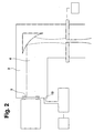
- the laser processing machine shown in Figure 2 differs from the laser processing machine of Figure 1, characterized in that the inlet opening 13 opens for the purge gas parallel to the optical axis of the optical window 2 in the beam guiding space 3.
- the purge gas is thus flowed via the inlet opening 13 away from the optical window 2 in the beam guiding space 3.
- This arrangement of the inlet opening 13 has the advantage that purge gases with a lower degree of purity, such as compressed air or the filtered exhaust air of a vacuum pump, which sucks laser gas from the laser resonator, can be flowed in, since the purge gas is not directed to the optical window 2.
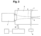
- the laser processing machine shown in Figure 3 differs from the laser processing machine of Figure 1 in that the optical window and the focusing device are replaced by a single optical element 14 and that the inlet opening 15 for the purge gas, for example by means of a nozzle, on the surface of the optical Elements 14 is directed.
- the laser beam enters the beam guiding space 3 via the optical element 14.
- the laser beam is focused by the optical element 14 and directed to the diaphragm 7, which is arranged in the beam path of the focused laser beam 6.
- the flushing gas impinging on the surface of the optical element 14 the deposition of impurities on the optical element 14 is counteracted.
- the laser beam 4 is coupled out of the laser resonator 1 via the optical window 2 and enters a beam guiding tube 17 .
- a cutting head 18 At the end of the laser beam 4 is coupled into a cutting head 18 .
- the laser beam 4 is focused in the interior of the cutting head 18 by means of a focusing device in the form of a focusing mirror 19 through a diaphragm 21 onto a sheet 22 to be processed.
- the cutting head 18 and the plate 22 are displaceable relative to each other.
- the cutting head 18 and the beam guide tube 17 remain stationary during processing of the sheet. In addition, it is possible to leave the sheet stationary during processing and to move the cutting head with the beam guide tube.
- the sheet 22 is displaceably clamped to a coordinate feed 24 relative to the cutting head 18 and mounted on a workpiece support 25 .
- the beam guiding tube 17 and the cutting head 18 together form the beam guiding space 3 into which the flushing gas flows via the inlet opening 10 on the beam guiding tube 17 and out again via the aperture 23 on the cutting head 18.
- the purge gas supply into the jet guide chamber 3 is regulated so that there is an overpressure against the outside and the aperture 23 forms a throttle point for the purge gas.
- the purge gas which is directed via the nozzle-shaped aperture 21 to the sheet 22, at the same time serves as a cutting gas for expelling the liquid material from the kerf generated in the sheet 22 kerf.
- the beam waist of the focused laser beam 6 is not located at the location of the diaphragm 7, but its position is determined by the position of the sheet 22 and the processing task.
Landscapes
- Physics & Mathematics (AREA)
- Optics & Photonics (AREA)
- Engineering & Computer Science (AREA)
- Plasma & Fusion (AREA)
- Mechanical Engineering (AREA)
- Laser Beam Processing (AREA)
Abstract
Description

- Fig. 1
- ein erstes Ausführungsbeispiel der erfindungsgemäßen Laserbearbeitungsmaschine, wobei der Bearbeitungskopf nicht dargestellt ist;
- Fig. 2
- ein zweites Ausführungsbeispiel der erfindungsgemäßen Laserbearbeitungsmaschine, wobei der Bearbeitungskopf nicht dargestellt ist;
- Fig. 3
- ein drittes Ausführungsbeispiel der erfindungsgemäßen Laserbearbeitungsmaschine, wobei der Bearbeitungskopf nicht dargestellt ist; und
- Fig. 4
- ein viertes Ausführungsbeispiel der erfindungsgemäßen Laserbearbeitungsmaschine.

| Öffnungsdurchmesser der Blende [mm] | Überdruck vor der Blende [mbar] |
| 0,95 | 4500 |
| 1,6 | 1100 |
| 1,9 | 550 |
| 2,3 | 250 |
| 4, 0 | 73 |
| 4,5 | 64 |
| 5,0 | 58 |
| 5,5 | 56 |
| 6, 0 | 53 |
Claims (11)
- Laserbearbeitungsmaschine mit einem gasgespülten Strahlführungsraum (3) und mit einem den Strahlführungsraum (3) lichteintrittsseitig begrenzenden optischen Element (2; 14) zum Einkoppeln des Laserstrahls (4) in den Strahlführungsraum (3), wobei der Strahlführungsraum (3) nahe dem optischen Element (2; 14) eine Eintrittsöffnung (10; 13; 15) für ein Spülgas aufweist,
dadurch gekennzeichnet, daß eine im Strahlführungsraum (3) zur Strahlformung des Laserstrahls (4) vorgesehene optische Blende (7; 21) gleichzeitig eine Drosselstelle für das Spülgas bildet. - Laserbearbeitungsmaschine nach Anspruch 1, gekennzeichnet durch eine Fokussiereinrichtung (5; 14; 19), die den Laserstrahl in Richtung auf die Blende (7; 21) fokussiert.
- Laserbearbeitungsmaschine nach Anspruch 2, dadurch gekennzeichnet, daß die Fokussiereinrichtung (5; 19) in das optische Element (14) integriert oder innerhalb des Strahlführungsraums (3) angeordnet ist.
- Laserbearbeitungsmaschine nach Anspruch 2 oder 3, dadurch gekennzeichnet, daß die Blende (7; 21) innerhalb der Rayleighlänge von der Strahltaille des von der Fokussiereinrichtung (5; 14; 19) fokussierten Laserstrahls (6) entfernt angeordnet ist.
- Laserbearbeitungsmaschine nach einem der vorhergehenden Ansprüche, dadurch gekennzeichnet, daß die Blendenöffnung (9; 23) mittels einer Stelleinrichtung (8) verstellbar ist.
- Laserbearbeitungsmaschine nach einem der vorhergehenden Ansprüche, dadurch gekennzeichnet, daß die Blendenöffnung (9; 23) kreisförmig ist und ihr Durchmesser kleiner alsist.

- Laserbearbeitungsmaschine nach einem der vorhergehenden Ansprüche, dadurch gekennzeichnet, daß die Eintrittsöffnung (10; 13; 15) das in den Strahlführungsraum (3) einströmende Spülgas auf das optische Element (2; 14), parallel zur Oberfläche des optischen Elements (2; 14) oder fort vom optischen Element (2; 14) richtet.
- Laserbearbeitungsmaschine nach einem der vorhergehenden Ansprüche, dadurch gekennzeichnet, daß die Blende (21) und die Drosselstelle durch eine Schneidgasdüse am Schneidkopf (18) der Laserbearbeitungsmaschine gebildet sind und daß das Spülgas gleichzeitig bei der Laserbearbeitung als Bearbeitungsgas dient.
- Verfahren zum Schutz eines im gasgespülten Strahlführungsraum (3) eines Laserstrahls (4) vorgesehenen optischen Elements (2; 14) vor Verunreinigungen,
dadurch gekennzeichnet, daß der Druck des den Strahlführungsraum (3) durchströmenden Spülgases so eingestellt wird, daß eine im Strahlführungsraum (3) zur Strahlformung des Laserstrahls (4) vorgesehene optische Blende (7; 21) gleichzeitig als Drosselstelle für das Spülgas wirkt. - Verwendung einer optischen Blende (7) für einen Laserstrahl (4) gleichzeitig als Drosselstelle für ein Spülgas zum Spülen eines Strahlführungsraums (3).
- Verwendung einer Schneidgasdüse als optische Blende (21) für einen Laserstrahl (4) und als Drosselstelle für ein gleichzeitig als Bearbeitungsgas dienendes Spülgas zum Spülen eines Strahlführungsraums (3).
Priority Applications (4)
| Application Number | Priority Date | Filing Date | Title |
|---|---|---|---|
| EP00117505A EP1180409B1 (de) | 2000-08-12 | 2000-08-12 | Laserbearbeitungsmaschine mit gasgespültem Strahlführungsraum |
| AT00117505T ATE291986T1 (de) | 2000-08-12 | 2000-08-12 | Laserbearbeitungsmaschine mit gasgespültem strahlführungsraum |
| DE50009924T DE50009924D1 (de) | 2000-08-12 | 2000-08-12 | Laserbearbeitungsmaschine mit gasgespültem Strahlführungsraum |
| US09/927,819 US6624386B2 (en) | 2000-08-12 | 2001-08-10 | Laser processing machine with gas flushed beam guiding chamber |
Applications Claiming Priority (1)
| Application Number | Priority Date | Filing Date | Title |
|---|---|---|---|
| EP00117505A EP1180409B1 (de) | 2000-08-12 | 2000-08-12 | Laserbearbeitungsmaschine mit gasgespültem Strahlführungsraum |
Publications (2)
| Publication Number | Publication Date |
|---|---|
| EP1180409A1 true EP1180409A1 (de) | 2002-02-20 |
| EP1180409B1 EP1180409B1 (de) | 2005-03-30 |
Family
ID=8169520
Family Applications (1)
| Application Number | Title | Priority Date | Filing Date |
|---|---|---|---|
| EP00117505A Expired - Lifetime EP1180409B1 (de) | 2000-08-12 | 2000-08-12 | Laserbearbeitungsmaschine mit gasgespültem Strahlführungsraum |
Country Status (4)
| Country | Link |
|---|---|
| US (1) | US6624386B2 (de) |
| EP (1) | EP1180409B1 (de) |
| AT (1) | ATE291986T1 (de) |
| DE (1) | DE50009924D1 (de) |
Cited By (4)
| Publication number | Priority date | Publication date | Assignee | Title |
|---|---|---|---|---|
| EP1623790A1 (de) * | 2004-08-06 | 2006-02-08 | Trumpf Werkzeugmaschinen GmbH + Co. KG | Laserbearbeitungskopf |
| WO2007025562A1 (de) * | 2005-09-03 | 2007-03-08 | Trumpf Werkzeugmaschinen Gmbh + Co. Kg | Laserbearbeitungsmaschine mit einer optischen blende zur randfeldbeseitigung |
| WO2007128333A1 (de) * | 2006-05-09 | 2007-11-15 | Trumpf Laser- Und Systemtechnik Gmbh | Laserbearbeitungsmaschine mit einer einrichtung zum belüften der laserstrahlführung und verfahren zum belüften der laserstrahlführung einer laserbearbeitungsmaschine |
| CN107782671A (zh) * | 2017-10-25 | 2018-03-09 | 蓝靖 | 一种光谱分析仪器中光学元件的气体保护装置 |
Families Citing this family (15)
| Publication number | Priority date | Publication date | Assignee | Title |
|---|---|---|---|---|
| US20030155328A1 (en) * | 2002-02-15 | 2003-08-21 | Huth Mark C. | Laser micromachining and methods and systems of same |
| US6683277B1 (en) * | 2002-12-20 | 2004-01-27 | Osram Opto Semiconductors | Laser ablation nozzle assembly |
| DE20306336U1 (de) * | 2003-04-22 | 2003-06-26 | TRUMPF Werkzeugmaschinen GmbH & Co. KG, 71254 Ditzingen | Strahlführung einer Laserbearbeitungsmaschine |
| US6969822B2 (en) * | 2003-05-13 | 2005-11-29 | Hewlett-Packard Development Company, L.P. | Laser micromachining systems |
| US7754999B2 (en) | 2003-05-13 | 2010-07-13 | Hewlett-Packard Development Company, L.P. | Laser micromachining and methods of same |
| DE102004004514A1 (de) * | 2004-01-23 | 2005-08-18 | Carl Zeiss | Vorrichtung und Verfahren zum Signieren eines Brillenglases |
| DE102004049241A1 (de) * | 2004-10-09 | 2006-04-20 | Sanofi-Aventis Deutschland Gmbh | Trockner und Verfahren zum Steuern eines Trockners |
| EP1658921B1 (de) * | 2004-11-17 | 2017-01-18 | TRUMPF Laser GmbH | Laserschweissvorrichtung für Hochleistungslaser mit hoher Strahlqualität und Fokussieroptiken mit langer Brennweite |
| US20080169273A1 (en) * | 2007-01-12 | 2008-07-17 | Nickolas Bizzio | Laser cavity particularly for laser welding apparatus |
| GB0816308D0 (en) | 2008-09-05 | 2008-10-15 | Mtt Technologies Ltd | Optical module |
| DE102015211999A1 (de) * | 2015-06-29 | 2016-12-29 | Trumpf Werkzeugmaschinen Gmbh + Co. Kg | Laserbearbeitungskopf und Laserbearbeitungsmaschine damit |
| EP3377253B1 (de) | 2015-11-16 | 2023-03-01 | Renishaw PLC | Modul für vorrichtung zur generativen fertigung |
| CN110709195B (zh) * | 2017-03-31 | 2022-05-03 | 株式会社尼康 | 造型系统及造型方法 |
| CN112828313A (zh) * | 2020-12-21 | 2021-05-25 | 安徽省春谷3D打印智能装备产业技术研究院有限公司 | 一种3d打印用轨迹可调的激光熔覆装置 |
| EP4263897A1 (de) * | 2021-01-27 | 2023-10-25 | Max-Planck-Gesellschaft zur Förderung der Wissenschaften e.V. | Thermisches laserverdampfungssystem |
Citations (6)
| Publication number | Priority date | Publication date | Assignee | Title |
|---|---|---|---|---|
| US3685882A (en) * | 1970-11-02 | 1972-08-22 | Westinghouse Electric Corp | Self-aligned gas assisted lens for laser beam apparatus |
| US4467171A (en) * | 1982-09-30 | 1984-08-21 | The United States Of America As Represented By The United States Department Of Energy | Laser cutting nozzle |
| GB2163692A (en) * | 1984-08-30 | 1986-03-05 | Ferranti Plc | Laser apparatus |
| DE4001091A1 (de) * | 1990-01-17 | 1991-07-18 | Deutsche Forsch Luft Raumfahrt | Vorrichtung zur energetisierung einer substanz |
| DE4305107A1 (de) * | 1993-02-19 | 1994-08-25 | Fraunhofer Ges Forschung | Verfahren und Vorrichtung zum Schneiden eines spröden Körpers mit Laserstrahlung |
| EP0749800A2 (de) * | 1995-06-19 | 1996-12-27 | Trumpf GmbH & Co | Laserbearbeitungsmaschine mit gasgefülltem Strahlführungsraum |
Family Cites Families (4)
| Publication number | Priority date | Publication date | Assignee | Title |
|---|---|---|---|---|
| JPH04344886A (ja) * | 1991-05-22 | 1992-12-01 | Amada Co Ltd | レーザ加工ヘッド |
| DE19734715A1 (de) * | 1997-08-11 | 1999-02-25 | Lambda Physik Gmbh | Vorrichtung zum Spülen des Strahlenganges eines UV-Laserstrahles |
| JPH11347772A (ja) * | 1998-06-09 | 1999-12-21 | Shin Nippon Koki Co Ltd | レーザ加工機用レーザビームトリミング装置及びレーザビームトリミング方法 |
| FR2781707B1 (fr) * | 1998-07-30 | 2000-09-08 | Snecma | Procede d'usinage par laser excimere de trous ou de formes a profil variable |
-
2000
- 2000-08-12 DE DE50009924T patent/DE50009924D1/de not_active Expired - Lifetime
- 2000-08-12 EP EP00117505A patent/EP1180409B1/de not_active Expired - Lifetime
- 2000-08-12 AT AT00117505T patent/ATE291986T1/de not_active IP Right Cessation
-
2001
- 2001-08-10 US US09/927,819 patent/US6624386B2/en not_active Expired - Lifetime
Patent Citations (6)
| Publication number | Priority date | Publication date | Assignee | Title |
|---|---|---|---|---|
| US3685882A (en) * | 1970-11-02 | 1972-08-22 | Westinghouse Electric Corp | Self-aligned gas assisted lens for laser beam apparatus |
| US4467171A (en) * | 1982-09-30 | 1984-08-21 | The United States Of America As Represented By The United States Department Of Energy | Laser cutting nozzle |
| GB2163692A (en) * | 1984-08-30 | 1986-03-05 | Ferranti Plc | Laser apparatus |
| DE4001091A1 (de) * | 1990-01-17 | 1991-07-18 | Deutsche Forsch Luft Raumfahrt | Vorrichtung zur energetisierung einer substanz |
| DE4305107A1 (de) * | 1993-02-19 | 1994-08-25 | Fraunhofer Ges Forschung | Verfahren und Vorrichtung zum Schneiden eines spröden Körpers mit Laserstrahlung |
| EP0749800A2 (de) * | 1995-06-19 | 1996-12-27 | Trumpf GmbH & Co | Laserbearbeitungsmaschine mit gasgefülltem Strahlführungsraum |
Cited By (9)
| Publication number | Priority date | Publication date | Assignee | Title |
|---|---|---|---|---|
| EP1623790A1 (de) * | 2004-08-06 | 2006-02-08 | Trumpf Werkzeugmaschinen GmbH + Co. KG | Laserbearbeitungskopf |
| US7605342B2 (en) | 2004-08-06 | 2009-10-20 | Trumpf Werkzeugmaschinen Gmbh + Co. Kg | Laser processing head |
| WO2007025562A1 (de) * | 2005-09-03 | 2007-03-08 | Trumpf Werkzeugmaschinen Gmbh + Co. Kg | Laserbearbeitungsmaschine mit einer optischen blende zur randfeldbeseitigung |
| CN101257992B (zh) * | 2005-09-03 | 2012-01-04 | 通快机床两合公司 | 具有用于消除弥散场的光学膜片的激光加工机床 |
| WO2007128333A1 (de) * | 2006-05-09 | 2007-11-15 | Trumpf Laser- Und Systemtechnik Gmbh | Laserbearbeitungsmaschine mit einer einrichtung zum belüften der laserstrahlführung und verfahren zum belüften der laserstrahlführung einer laserbearbeitungsmaschine |
| CN101443154A (zh) * | 2006-05-09 | 2009-05-27 | 通快激光与系统工程有限公司 | 具有激光束引导装置通风装置的激光加工机和激光加工机的激光束引导装置的通风方法 |
| US8203098B2 (en) | 2006-05-09 | 2012-06-19 | Trumpf Laser-Und Systemtechnik Gmbh | Laser processing machines and methods for providing a gas to the beam guide of a laser processing machine |
| CN101443154B (zh) * | 2006-05-09 | 2012-10-24 | 通快激光与系统工程有限公司 | 具有激光束引导装置通风装置的激光加工机和激光加工机的激光束引导装置的通风方法 |
| CN107782671A (zh) * | 2017-10-25 | 2018-03-09 | 蓝靖 | 一种光谱分析仪器中光学元件的气体保护装置 |
Also Published As
| Publication number | Publication date |
|---|---|
| US20020040894A1 (en) | 2002-04-11 |
| DE50009924D1 (de) | 2005-05-04 |
| US6624386B2 (en) | 2003-09-23 |
| ATE291986T1 (de) | 2005-04-15 |
| EP1180409B1 (de) | 2005-03-30 |
Similar Documents
| Publication | Publication Date | Title |
|---|---|---|
| EP1180409B1 (de) | Laserbearbeitungsmaschine mit gasgespültem Strahlführungsraum | |
| DE4418845C1 (de) | Verfahren und Vorrichtung zur Materialbearbeitung mit Hilfe eines Laserstrahls | |
| DE3821836C2 (de) | ||
| DE102014210838A1 (de) | Einkoppeloptik, Laserschweißkopf und Laserschweißvorrichtung mit Vakuumkammer | |
| EP2133171B1 (de) | Maschinelle Vorrichtung zum Bearbeiten von Werkstücken mittels eines Laserstrahls | |
| EP0199095B1 (de) | Laserschweissgerät | |
| DE2734759A1 (de) | Laserstrahl-schweissgeraet | |
| EP1182002B1 (de) | Laserbearbeitungsmaschine mit wenigstens einem mit einem Spülmedium beaufschlagbaren optischen Element | |
| DE10226359B4 (de) | Laserbearbeitungskopf zur Bearbeitung, insbesondere zum Schneiden eines Werkstücks mittels Laserstrahl | |
| EP0458180B1 (de) | Verfahren und Vorrichtung zum Laserstrahlschneiden | |
| DE102012003202A1 (de) | Vorrichtung und Verfahren zum Bearbeiten von Werkstücken, insbesondere von Schneiden oder mit Schneiden versehenen Werkstücken, mit einem Nasslaser | |
| EP1623790A1 (de) | Laserbearbeitungskopf | |
| DE3931401C2 (de) | Fokussierkopf für Laserschweißanlagen | |
| DE102019122228B4 (de) | Laserbearbeitungssystem und Laserbearbeitungsverfahren | |
| DE2211195A1 (de) | Verfahren und Vorrichtung zur Materialschweißung | |
| DE102021123027A1 (de) | Laser-Bearbeitungsvorrichtung | |
| DE60210143T2 (de) | Laserschneidverfahren und -vorrichtung | |
| EP3257616A1 (de) | Laserbearbeitungskopf mit gekühlten optischen komponenten und verfahren zum betreiben eines laserbearbeitungskopfes | |
| DE102022130840A1 (de) | Prozessmonitor für Laserbearbeitungskopf | |
| EP2024132A1 (de) | Laserbearbeitungsmaschine mit einer einrichtung zum belüften der laserstrahlführung und verfahren zum belüften der laserstrahlführung einer laserbearbeitungsmaschine | |
| DE102015013847A1 (de) | Laserschweißeinrichtung | |
| DE20318461U1 (de) | Lavaldüse für eine Crossjet-Vorrichtung | |
| DE4118693C2 (de) | Bearbeitungskopf für eine Vorrichtung zum Schneiden von Werkstücken mit Licht- oder Teilchenstrahlen | |
| WO2008043335A1 (de) | Fangeinrichtung und verfahren zum auffangen des schneidstrahls einer wasserstrahlbearbeitungsmaschine | |
| DE202004021568U1 (de) | Roboter |
Legal Events
| Date | Code | Title | Description |
|---|---|---|---|
| PUAI | Public reference made under article 153(3) epc to a published international application that has entered the european phase |
Free format text: ORIGINAL CODE: 0009012 |
|
| 17P | Request for examination filed |
Effective date: 20010723 |
|
| AK | Designated contracting states |
Kind code of ref document: A1 Designated state(s): AT BE CH CY DE DK ES FI FR GB GR IE IT LI LU MC NL PT SE Kind code of ref document: A1 Designated state(s): AT BE CH CY DE DK LI |
|
| AX | Request for extension of the european patent |
Free format text: AL;LT;LV;MK;RO;SI |
|
| AKX | Designation fees paid |
Free format text: AT BE CH CY DE DK LI |
|
| RBV | Designated contracting states (corrected) |
Designated state(s): AT CH DE FR GB IT LI |
|
| 17Q | First examination report despatched |
Effective date: 20030414 |
|
| GRAP | Despatch of communication of intention to grant a patent |
Free format text: ORIGINAL CODE: EPIDOSNIGR1 |
|
| GRAS | Grant fee paid |
Free format text: ORIGINAL CODE: EPIDOSNIGR3 |
|
| GRAA | (expected) grant |
Free format text: ORIGINAL CODE: 0009210 |
|
| AK | Designated contracting states |
Kind code of ref document: B1 Designated state(s): AT CH DE FR GB IT LI |
|
| REG | Reference to a national code |
Ref country code: GB Ref legal event code: FG4D Free format text: NOT ENGLISH |
|
| REG | Reference to a national code |
Ref country code: CH Ref legal event code: EP |
|
| GBT | Gb: translation of ep patent filed (gb section 77(6)(a)/1977) |
Effective date: 20050330 |
|
| REF | Corresponds to: |
Ref document number: 50009924 Country of ref document: DE Date of ref document: 20050504 Kind code of ref document: P |
|
| REG | Reference to a national code |
Ref country code: IE Ref legal event code: FG4D Free format text: LANGUAGE OF EP DOCUMENT: GERMAN |
|
| ET | Fr: translation filed | ||
| PLBE | No opposition filed within time limit |
Free format text: ORIGINAL CODE: 0009261 |
|
| STAA | Information on the status of an ep patent application or granted ep patent |
Free format text: STATUS: NO OPPOSITION FILED WITHIN TIME LIMIT |
|
| 26N | No opposition filed |
Effective date: 20060102 |
|
| PGFP | Annual fee paid to national office [announced via postgrant information from national office to epo] |
Ref country code: AT Payment date: 20080820 Year of fee payment: 9 Ref country code: IT Payment date: 20080826 Year of fee payment: 9 |
|
| PG25 | Lapsed in a contracting state [announced via postgrant information from national office to epo] |
Ref country code: AT Free format text: LAPSE BECAUSE OF NON-PAYMENT OF DUE FEES Effective date: 20090812 |
|
| PG25 | Lapsed in a contracting state [announced via postgrant information from national office to epo] |
Ref country code: IT Free format text: LAPSE BECAUSE OF NON-PAYMENT OF DUE FEES Effective date: 20090812 |
|
| REG | Reference to a national code |
Ref country code: FR Ref legal event code: PLFP Year of fee payment: 17 |
|
| REG | Reference to a national code |
Ref country code: FR Ref legal event code: PLFP Year of fee payment: 18 |
|
| REG | Reference to a national code |
Ref country code: FR Ref legal event code: PLFP Year of fee payment: 19 |
|
| PGFP | Annual fee paid to national office [announced via postgrant information from national office to epo] |
Ref country code: DE Payment date: 20190822 Year of fee payment: 20 Ref country code: FR Payment date: 20190822 Year of fee payment: 20 |
|
| PGFP | Annual fee paid to national office [announced via postgrant information from national office to epo] |
Ref country code: GB Payment date: 20190821 Year of fee payment: 20 |
|
| PGFP | Annual fee paid to national office [announced via postgrant information from national office to epo] |
Ref country code: CH Payment date: 20190821 Year of fee payment: 20 |
|
| REG | Reference to a national code |
Ref country code: CH Ref legal event code: PL |
|
| REG | Reference to a national code |
Ref country code: GB Ref legal event code: PE20 Expiry date: 20200811 |
|
| PG25 | Lapsed in a contracting state [announced via postgrant information from national office to epo] |
Ref country code: GB Free format text: LAPSE BECAUSE OF EXPIRATION OF PROTECTION Effective date: 20200811 |