EP1179693A2 - Automatic splitter control for manually shifted transmission - Google Patents
Automatic splitter control for manually shifted transmission Download PDFInfo
- Publication number
- EP1179693A2 EP1179693A2 EP01118095A EP01118095A EP1179693A2 EP 1179693 A2 EP1179693 A2 EP 1179693A2 EP 01118095 A EP01118095 A EP 01118095A EP 01118095 A EP01118095 A EP 01118095A EP 1179693 A2 EP1179693 A2 EP 1179693A2
- Authority
- EP
- European Patent Office
- Prior art keywords
- splitter
- ratio
- engine speed
- engaged
- section
- Prior art date
- Legal status (The legal status is an assumption and is not a legal conclusion. Google has not performed a legal analysis and makes no representation as to the accuracy of the status listed.)
- Granted
Links
Images


Classifications
-
- F—MECHANICAL ENGINEERING; LIGHTING; HEATING; WEAPONS; BLASTING
- F16—ENGINEERING ELEMENTS AND UNITS; GENERAL MEASURES FOR PRODUCING AND MAINTAINING EFFECTIVE FUNCTIONING OF MACHINES OR INSTALLATIONS; THERMAL INSULATION IN GENERAL
- F16H—GEARING
- F16H61/00—Control functions within control units of change-speed- or reversing-gearings for conveying rotary motion ; Control of exclusively fluid gearing, friction gearing, gearings with endless flexible members or other particular types of gearing
- F16H61/02—Control functions within control units of change-speed- or reversing-gearings for conveying rotary motion ; Control of exclusively fluid gearing, friction gearing, gearings with endless flexible members or other particular types of gearing characterised by the signals used
- F16H61/0202—Control functions within control units of change-speed- or reversing-gearings for conveying rotary motion ; Control of exclusively fluid gearing, friction gearing, gearings with endless flexible members or other particular types of gearing characterised by the signals used the signals being electric
- F16H61/0248—Control units where shifting is directly initiated by the driver, e.g. semi-automatic transmissions
-
- B—PERFORMING OPERATIONS; TRANSPORTING
- B60—VEHICLES IN GENERAL
- B60W—CONJOINT CONTROL OF VEHICLE SUB-UNITS OF DIFFERENT TYPE OR DIFFERENT FUNCTION; CONTROL SYSTEMS SPECIALLY ADAPTED FOR HYBRID VEHICLES; ROAD VEHICLE DRIVE CONTROL SYSTEMS FOR PURPOSES NOT RELATED TO THE CONTROL OF A PARTICULAR SUB-UNIT
- B60W2710/00—Output or target parameters relating to a particular sub-units
- B60W2710/06—Combustion engines, Gas turbines
- B60W2710/0644—Engine speed
-
- F—MECHANICAL ENGINEERING; LIGHTING; HEATING; WEAPONS; BLASTING
- F16—ENGINEERING ELEMENTS AND UNITS; GENERAL MEASURES FOR PRODUCING AND MAINTAINING EFFECTIVE FUNCTIONING OF MACHINES OR INSTALLATIONS; THERMAL INSULATION IN GENERAL
- F16H—GEARING
- F16H59/00—Control inputs to control units of change-speed-, or reversing-gearings for conveying rotary motion
- F16H59/36—Inputs being a function of speed
- F16H2059/366—Engine or motor speed
-
- F—MECHANICAL ENGINEERING; LIGHTING; HEATING; WEAPONS; BLASTING
- F16—ENGINEERING ELEMENTS AND UNITS; GENERAL MEASURES FOR PRODUCING AND MAINTAINING EFFECTIVE FUNCTIONING OF MACHINES OR INSTALLATIONS; THERMAL INSULATION IN GENERAL
- F16H—GEARING
- F16H61/00—Control functions within control units of change-speed- or reversing-gearings for conveying rotary motion ; Control of exclusively fluid gearing, friction gearing, gearings with endless flexible members or other particular types of gearing
- F16H61/70—Control functions within control units of change-speed- or reversing-gearings for conveying rotary motion ; Control of exclusively fluid gearing, friction gearing, gearings with endless flexible members or other particular types of gearing specially adapted for change-speed gearing in group arrangement, i.e. with separate change-speed gear trains arranged in series, e.g. range or overdrive-type gearing arrangements
- F16H61/702—Control functions within control units of change-speed- or reversing-gearings for conveying rotary motion ; Control of exclusively fluid gearing, friction gearing, gearings with endless flexible members or other particular types of gearing specially adapted for change-speed gearing in group arrangement, i.e. with separate change-speed gear trains arranged in series, e.g. range or overdrive-type gearing arrangements using electric or electrohydraulic control means
-
- Y—GENERAL TAGGING OF NEW TECHNOLOGICAL DEVELOPMENTS; GENERAL TAGGING OF CROSS-SECTIONAL TECHNOLOGIES SPANNING OVER SEVERAL SECTIONS OF THE IPC; TECHNICAL SUBJECTS COVERED BY FORMER USPC CROSS-REFERENCE ART COLLECTIONS [XRACs] AND DIGESTS
- Y10—TECHNICAL SUBJECTS COVERED BY FORMER USPC
- Y10S—TECHNICAL SUBJECTS COVERED BY FORMER USPC CROSS-REFERENCE ART COLLECTIONS [XRACs] AND DIGESTS
- Y10S477/00—Interrelated power delivery controls, including engine control
- Y10S477/908—In series transmission
Definitions
- the present invention relates to automatic splitter shifting in a manually shifted compound transmission having a lever-shifted main section connected in series with an auxiliary splitter or splitter-and-range section.
- the present invention relates to a splitter control for transmissions of the type described for automatically implementing splitter shifts and/or splitter-and-range shifts during a manual lever shift.
- Controller-assisted, manually shifted transmission systems are known in the prior art, as may be seen by reference to U.S. Pats. No. 5,582,558; 5,755,639; 5,766,111; 5,791,189; 5,974,906; 5,989,155 and 6,015,366, the disclosures of which are incorporated herein by reference.
- splitter shifts are automatically implemented and, during a lever shift, the splitter is shifted to neutral and retained in neutral until the main section is engaged in the position selected by the operator.
- the system controller must then determine if the splitter should be engaged/reengaged in splitter-high or splitter-low and command engagement of the appropriate splitter ratio.
- a manually shifted compound transmission with a splitter or combined splitter-and-range auxiliary section which will automatically shift the splitter section and/or automatically disengage and then reengage the splitter section during a lever shift.
- Logic rules are provided to determine which splitter ratio should be reengaged after the splitter is shited to neutral during a manual lever shift.
- a manually shifted compound transmission having a lever-shifted main section connected in series with a splitter or combined splitter-and-range auxiliary section having an actuator for automatically implementing controller-initiated splitter shifts by sensing vehicle operating conditions, determining a target engine speed under such conditions, and engaging the splitter section in the splitter ratio which will result in an engine speed closest to the target engine speed.
- the target engine speed will be midway between the upshift and downshift engine speeds for existing vehicle operating conditions.
- a display and/or alarm or the like will be activated to inform the driver of the currently engaged ratio and/or splitter position.
- a computer-assisted (i.e. , microprocessor-based, controller-assisted) vehicular compound mechanical transmission system 10, particularly well suited to utilize the splitter shifting control of the present invention, may be seen by reference to Figs. 1, 2, 3 and 4.
- System 10 is of the type commonly utilized in heavy-duty vehicles and includes an engine, typically a diesel engine 12, a master friction clutch 14 contained within a clutch housing, a multiple-speed compound transmission 16, and a vehicular drive axle assembly 18.
- the transmission 16 includes an output shaft 20 drivingly coupled to a vehicle drive shaft 22 by universal joints for driving the drive axle assembly.
- Master friction clutch 14 includes driving friction members 14A driven by the engine and driven friction members 14B, which are carried by the transmission input shaft 24.
- Compound mechanical change-gear transmission 16 will typically include a main transmission section 16A and a splitter- or combined splitter-and-range-type auxiliary transmission section 16B, all contained within a common transmission housing 16C.
- Compound mechanical change-gear transmissions of this type are well known in the prior art, and examples thereof may be seen by reference to aforementioned U.S. Pats. No. 4,754,665 and 5,390,561.
- the main transmission section 16A is manually shifted by a manually operated shift lever 26, while the range-type auxiliary transmission section 168 is shifted by a splitter or splitter-and-range actuator assembly 28, one example of which is schematically illustrated in Fig. 3, to be described in greater detail below.
- a clutch pedal 30 is provided for manually operating master clutch 14, although clutch 14 could also be automatically operated within the scope of the present invention. Dynamic shifting may be done without disengaging the master clutch (see U.S. Pat. No. 4,850,236).
- Engine 12 is preferably electronically controlled and includes an engine controller 32 communicating over an electronic data link DL.
- the data link will operate under an industry standard protocol, such as SAE J-1922, SAE J-1939, ISO 11898 or the like.
- the system also may include an engine compression brake 34 and/or an input shaft retarding device, such as an inertia brake 36.
- the system may include sensors 38 for sensing engine rotational speed (ES), 40 for sensing input shaft rotational speed (IS), 42 for sensing output shaft rotational speed (OS), 44 for sensing the engaged or disengaged condition of the clutch, 46 for sensing the operator-set throttle pedal position (THL), 48 for sensing operation of the vehicle brake system (BRK), 50 for sensing the position of the main section shifting mechanism (MS), and the like.
- Position sensor 50 will send an output signal LP indicative of lever position in a shift pattern (see U.S. Pat. No. 5,743,143, the disclosure of which is incorporated herein by reference). Signal LP will be indicative of the engaged or being-engaged main section ratio.
- Signal LP will be indicative of the engaged or being-engaged main section ratio.
- controller 54 which will process same according to predetermined logic rules to issue command output signals 56 to various system actuators.
- the controller or ECU 54 is preferably a microprocessor-based control unit of the type illustrated in U.S. Pats. No. 4,595,986; 4,361,065 and 5,335,566, the disclosures of which are incorporated herein by reference. Controller 54 may be incorporated into the engine control 32.
- the system actuators operated by the ECU output signals 56 will include the splitter section actuator 28 and possibly the engine controller 32, the engine compression brake 34, the input shaft or upshift brake 36, and a display unit 58.
- ECU 54 may include a timing unit 60.
- the splitter shift mechanism 28 may be seen in greater detail by reference to the schematic illustration of Fig. 3.
- the three-position splitter shift mechanism 28 includes a shift fork 62 for positioning a splitter clutch, typically a double-sided jaw clutch, in either the splitter-high, splitter-neutral or splitter-low position.
- Shift fork 62 is carried or positioned by a piston 64 having a piston face 66 exposed to selectively pressurized and exhausted chamber 68 and a piston face 70 exposed to the selectively pressurized and exhausted piston chamber 72.
- Chamber 68 and chamber 72 are selectively pressurized and exhausted by means of a two-position, three-way, solenoid-controlled valve 74, which will selectively connect conduits 68A and 72A to either the source of pressurized fluid 76 or to an exhaust to atmosphere 78.
- the solenoid-controlled valve 74 is operated in response to command output signals 56 from the ECU 54, which may involve pulse-width modulation or the like. See also, U.S. Pat. No. 5,661,998, the disclosure of which is incorporated herein by reference. While a pressure-actuated range shift mechanism 28 is illustrated, it is understood that, within the scope of the present invention, the range shift mechanism 28 could also utilize hydraulic and/or electric actuators or the like.
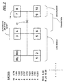
- Fig. 2 schematically illustrates the shift pattern for a preferred embodiment of compound transmission 16.
- the transmission is a 10-forward-speed transmission having a combined range-and-splitter-type auxiliary section.
- Transmissions of this type are well known in the prior art and are sold under the trademark 'Super-10' by the assignee of this invention, Eaton Corporation, and may be seen in greater detail by reference to U.S. Pat. No. 5,000,060, the disclosure of which is incorporated herein by reference.
- each of the large rectangular blocks of the shift pattern represents a shift lever position, while the vertical divisions of the blocks represent (preferably automatic) splitter shifts within each shift lever position.
- the main transmission section 16A has four selectively engageable main section ratios, one for reverse, one for 1/2, one for 3/4 or 7/8, and one for 5/6 or 9/10.
- the 3/4 shift lever position engages the same main section gear as does the 7/8 shift lever position.
- the range is in the low range ratio
- the 7/8 shift lever position the range is in the high ratio.
- Shift patterns of this type are commonly referred to as "double-H” type shift patterns.
- range shifts may be manually implemented by using a range position selector 26A, as shown in dotted lines in Fig. 1.
- Assisted, manually shifted transmission 10 will have fully automatic splitter shifting, as shown in aforementioned U.S. Pat. No. 5,755,639, and/or will automatically shift to transmission-neutral during lever shifts and then reengage in an appropriate splitter ratio after the main section has engaged, as shown in aforementioned U.S. Pat. No. 6,044,721.
- As vehicle speeds often change during a shift it is necessary to provide logic rules for determining the splitter ratio to be engaged at completion of a lever shift involving an automatic shift to splitter-neutral during the lever shift.
- the splitter when the splitter ratio is being automatically engaged from a splitter-neutral position, the splitter will be engaged in the splitter ratio (splitter-high or splitter-low) which, under current or expected vehicle operation conditions, will result in engine speed most closely equaling a target engine speed.
- the target engine speed will be a value which is determined as a function of operator throttle position (also percent demand for engine torque).
- the target engine speed 100 is midway between the upshift and downshift engine speed for a particular throttle position (torque demand).
- the splitter control of the present invention is shown in flow chart format in Fig. 5.
Landscapes
- Engineering & Computer Science (AREA)
- General Engineering & Computer Science (AREA)
- Mechanical Engineering (AREA)
- Control Of Transmission Device (AREA)
- Control Of Vehicle Engines Or Engines For Specific Uses (AREA)
- Control Of Driving Devices And Active Controlling Of Vehicle (AREA)
- Structure Of Transmissions (AREA)
Abstract
Description
- The present invention relates to automatic splitter shifting in a manually shifted compound transmission having a lever-shifted main section connected in series with an auxiliary splitter or splitter-and-range section. In particular, the present invention relates to a splitter control for transmissions of the type described for automatically implementing splitter shifts and/or splitter-and-range shifts during a manual lever shift.
- Controller-assisted, manually shifted transmission systems are known in the prior art, as may be seen by reference to U.S. Pats. No. 5,582,558; 5,755,639; 5,766,111; 5,791,189; 5,974,906; 5,989,155 and 6,015,366, the disclosures of which are incorporated herein by reference.
- Compound transmissions having a range and/or combined range-and-splitter-type auxiliary transmission section are well known in the prior art, as may be seen by reference to U.S. Pats. No. 4,754,665 and 5,390,561, the disclosures of which are incorporated herein by reference.
- Transmissions having manually shifted main sections and automatically shifted splitter sections are known in the prior art, as may be seen by reference to U.S. Pats. No. 5,435,212; 5,938,711; 6,007,455 and 6,044,721, the disclosures of which are incorporated herein by reference.
- Compound transmissions having automatically implemented range shifting are well known in the prior art, as may be seen by reference to U.S. Pats. No. 5,911,787 and 5,974,906, the disclosures of which are incorporated herein by reference.
- In certain controller-assisted, manually shifted transmissions, splitter shifts are automatically implemented and, during a lever shift, the splitter is shifted to neutral and retained in neutral until the main section is engaged in the position selected by the operator. The system controller must then determine if the splitter should be engaged/reengaged in splitter-high or splitter-low and command engagement of the appropriate splitter ratio.
- In accordance with the present invention, a manually shifted compound transmission with a splitter or combined splitter-and-range auxiliary section is provided which will automatically shift the splitter section and/or automatically disengage and then reengage the splitter section during a lever shift. Logic rules are provided to determine which splitter ratio should be reengaged after the splitter is shited to neutral during a manual lever shift.
- The foregoing is accomplished in a manually shifted compound transmission having a lever-shifted main section connected in series with a splitter or combined splitter-and-range auxiliary section having an actuator for automatically implementing controller-initiated splitter shifts by sensing vehicle operating conditions, determining a target engine speed under such conditions, and engaging the splitter section in the splitter ratio which will result in an engine speed closest to the target engine speed. Preferably, the target engine speed will be midway between the upshift and downshift engine speeds for existing vehicle operating conditions. Preferably, a display and/or alarm or the like will be activated to inform the driver of the currently engaged ratio and/or splitter position.
- Accordingly, it is an object of the present invention to provide a new and improved splitter shift control for manually shifted compound transmissions having a splitter shifter for automatically implementing splitter shifts.
- This and other objects and advantages of the present invention will become apparent from a reading of the following description of the preferred embodiment taken in connection with the attached drawings.
-
- Fig. 1 is a schematic illustration of a controller-assisted, manually shifted compound transmission advantageously utilizing the splitter control of the present invention.
- Fig. 2 is a schematic illustration of a shift pattern for a preferred embodiment of the transmission of Fig. 1.
- Fig. 2A is a schematic illustration of an alternate shift pattern for an embodiment of the transmission of Fig. 1.
- Fig. 3 is an enlarged schematic illustration of a preferred embodiment of the splitter shift mechanism of the present invention.
- Fig. 4 is a chart of upshift and downshift engine speeds and target engine speeds at various throttle positions (expressed as a percent of maximum engine torque).
- Fig. 5 is a schematic illustration, in flow chart format, of the splitter control of the present invention.
-
- A computer-assisted (i.e., microprocessor-based, controller-assisted) vehicular compound
mechanical transmission system 10, particularly well suited to utilize the splitter shifting control of the present invention, may be seen by reference to Figs. 1, 2, 3 and 4. -
System 10 is of the type commonly utilized in heavy-duty vehicles and includes an engine, typically adiesel engine 12, amaster friction clutch 14 contained within a clutch housing, a multiple-speed compound transmission 16, and a vehiculardrive axle assembly 18. Thetransmission 16 includes anoutput shaft 20 drivingly coupled to avehicle drive shaft 22 by universal joints for driving the drive axle assembly. -
Master friction clutch 14 includesdriving friction members 14A driven by the engine and drivenfriction members 14B, which are carried by thetransmission input shaft 24. Compound mechanical change-gear transmission 16 will typically include amain transmission section 16A and a splitter- or combined splitter-and-range-type auxiliary transmission section 16B, all contained within acommon transmission housing 16C. Compound mechanical change-gear transmissions of this type are well known in the prior art, and examples thereof may be seen by reference to aforementioned U.S. Pats. No. 4,754,665 and 5,390,561. - The
main transmission section 16A is manually shifted by a manually operatedshift lever 26, while the range-typeauxiliary transmission section 168 is shifted by a splitter or splitter-and-range actuator assembly 28, one example of which is schematically illustrated in Fig. 3, to be described in greater detail below. - A
clutch pedal 30 is provided for manuallyoperating master clutch 14, althoughclutch 14 could also be automatically operated within the scope of the present invention. Dynamic shifting may be done without disengaging the master clutch (see U.S. Pat. No. 4,850,236). -
Engine 12 is preferably electronically controlled and includes anengine controller 32 communicating over an electronic data link DL. Preferably, the data link will operate under an industry standard protocol, such as SAE J-1922, SAE J-1939, ISO 11898 or the like. The system also may include anengine compression brake 34 and/or an input shaft retarding device, such as aninertia brake 36. - The system may include
sensors 38 for sensing engine rotational speed (ES), 40 for sensing input shaft rotational speed (IS), 42 for sensing output shaft rotational speed (OS), 44 for sensing the engaged or disengaged condition of the clutch, 46 for sensing the operator-set throttle pedal position (THL), 48 for sensing operation of the vehicle brake system (BRK), 50 for sensing the position of the main section shifting mechanism (MS), and the like.Position sensor 50 will send an output signal LP indicative of lever position in a shift pattern (see U.S. Pat. No. 5,743,143, the disclosure of which is incorporated herein by reference). Signal LP will be indicative of the engaged or being-engaged main section ratio. These and other sensors will sendinput signals 52 to acontroller 54, which will process same according to predetermined logic rules to issuecommand output signals 56 to various system actuators. - The controller or
ECU 54 is preferably a microprocessor-based control unit of the type illustrated in U.S. Pats. No. 4,595,986; 4,361,065 and 5,335,566, the disclosures of which are incorporated herein by reference.Controller 54 may be incorporated into theengine control 32. - The system actuators operated by the
ECU output signals 56 will include thesplitter section actuator 28 and possibly theengine controller 32, theengine compression brake 34, the input shaft orupshift brake 36, and adisplay unit 58. ECU 54 may include atiming unit 60. - The
splitter shift mechanism 28 may be seen in greater detail by reference to the schematic illustration of Fig. 3. The three-positionsplitter shift mechanism 28 includes ashift fork 62 for positioning a splitter clutch, typically a double-sided jaw clutch, in either the splitter-high, splitter-neutral or splitter-low position.Shift fork 62 is carried or positioned by apiston 64 having apiston face 66 exposed to selectively pressurized andexhausted chamber 68 and apiston face 70 exposed to the selectively pressurized andexhausted piston chamber 72.Chamber 68 andchamber 72 are selectively pressurized and exhausted by means of a two-position, three-way, solenoid-controlledvalve 74, which will selectively connectconduits fluid 76 or to an exhaust toatmosphere 78. The solenoid-controlledvalve 74 is operated in response tocommand output signals 56 from theECU 54, which may involve pulse-width modulation or the like. See also, U.S. Pat. No. 5,661,998, the disclosure of which is incorporated herein by reference. While a pressure-actuatedrange shift mechanism 28 is illustrated, it is understood that, within the scope of the present invention, therange shift mechanism 28 could also utilize hydraulic and/or electric actuators or the like. - Fig. 2 schematically illustrates the shift pattern for a preferred embodiment of
compound transmission 16. In the embodiment illustrated in Fig. 2, the transmission is a 10-forward-speed transmission having a combined range-and-splitter-type auxiliary section. Transmissions of this type are well known in the prior art and are sold under the trademark 'Super-10' by the assignee of this invention, Eaton Corporation, and may be seen in greater detail by reference to U.S. Pat. No. 5,000,060, the disclosure of which is incorporated herein by reference. As is known, each of the large rectangular blocks of the shift pattern represents a shift lever position, while the vertical divisions of the blocks represent (preferably automatic) splitter shifts within each shift lever position. Themain transmission section 16A has four selectively engageable main section ratios, one for reverse, one for 1/2, one for 3/4 or 7/8, and one for 5/6 or 9/10. In other words, the 3/4 shift lever position engages the same main section gear as does the 7/8 shift lever position. However, in the 3/4 position, the range is in the low range ratio, and in the 7/8 shift lever position, the range is in the high ratio. As the shift lever is moved from the middle leg of the shift pattern (3/4 and 5/6) to the left leg (7/8 and 9/10), a manual selection or initiation of an automatically implemented range shift occurs. Shift patterns of this type are commonly referred to as "double-H" type shift patterns. Alternatively, in a "repeat-H" type shift pattern, range shifts may be manually implemented by using arange position selector 26A, as shown in dotted lines in Fig. 1. - Assisted, manually shifted
transmission 10 will have fully automatic splitter shifting, as shown in aforementioned U.S. Pat. No. 5,755,639, and/or will automatically shift to transmission-neutral during lever shifts and then reengage in an appropriate splitter ratio after the main section has engaged, as shown in aforementioned U.S. Pat. No. 6,044,721. As vehicle speeds often change during a shift, it is necessary to provide logic rules for determining the splitter ratio to be engaged at completion of a lever shift involving an automatic shift to splitter-neutral during the lever shift. - According to the present invention, when the splitter ratio is being automatically engaged from a splitter-neutral position, the splitter will be engaged in the splitter ratio (splitter-high or splitter-low) which, under current or expected vehicle operation conditions, will result in engine speed most closely equaling a target engine speed. The target engine speed will be a value which is determined as a function of operator throttle position (also percent demand for engine torque).
- In a preferred embodiment of the present invention (see Fig. 4), the
target engine speed 100 is midway between the upshift and downshift engine speed for a particular throttle position (torque demand). - By way of example, referring to Figs. 2 and 4, assuming a 75% engine torque demand (line 106) and an expected output shaft speed of 1000 RPM (OS = 1000) at completion of a lever shift to the 7/8
lever position 108,target engine speed 110 equals about 1520 RPM (EST = 1520), engine speed in7th gear 112 will be about 1780 RPM (ES7 = 1780), and engine speed in8th gear 114 will be about 1330 RPM (ES8 = 1330). The expected engine speeds are calculated using the known relationship that, with the clutch engaged, ES = IS = OS*GR. - Accordingly, in splitter-high (8th gear), the difference between engine speed and target engine speed is about 190 RPM (EST - ESB =1520 -1330 = 190 RPM), while in splitter-low (7th gear), the difference between engine speed and target engine speed is about 260 RPM (ES7 - EST = 1780 - 1520 = 260 RPM). Accordingly, splitter-high (or 8th speed) will be engaged.
- The splitter control of the present invention is shown in flow chart format in Fig. 5.
- Accordingly, it may be seen that a new and improved splitter control is provided.
- Although the present invention has been described with a certain degree of particularity, it is understood that the description of the preferred embodiment is by way of example only and that numerous changes to form and detail are possible without departing from the spirit and scope of the invention as hereinafter claimed.
Claims (14)
- A method for controlling splitter shifting in a controller-assisted, manually shifted vehicular transmission system (10) comprising an internal combustion engine (12) driving an input shaft (24) of a compound transmission (16) having a multiple-ratio main section (16A) shifted by a shift lever (26) manually movable in a shift pattern and a splitter auxiliary section (16B) connected in series with said main section, said splitter auxiliary section shiftable to a selected one of (i) splitter-high ratio, (ii) splitter-neutral and (iii) splitter-low ratio, a splitter shift mechanism (28) for automatically implementing splitter shifts and a controller (54) for receiving input signals (52) indicative of system operating conditions and for processing same according to predetermined logic rules to issue command output signals (56) to system actuators, including said splitter shift mechanism, said method comprising the steps:sensing one of (i) a currently engaged condition of the main section and (ii) an intended engaged condition of the main section;determining if the splitter section is in the splitter-high, splitter-neutral or splitter-low position;determining a target engine speed (EST) under existing vehicle operating conditions;if (i) said main section is one of (1) engaged and (2) engaging in a known ratio and (ii) said auxiliary section is in splitter-neutral;(a) determining expected engine speed if said auxiliary section is engaged in splitter-high ratio (ESSPLITTER-HIGH) and expected engine speed if said auxiliary section is engaged in splitter-low ratio (ESSPLITTER-LOW), and(b) commanding the splitter auxiliary section to be engaged in a splitter ratio determined as a function of said target engine speed and said expected engine speeds.
- The method of claim 1 wherein said target engine speed at existing vehicle operating conditions (110) is determined as a function of upshift (102) and downshift (104) engine speeds at existing vehicle operating conditions.
- The method of claim 2 wherein said target engine speed at existing vehicle operating conditions is about the average of said upshift and downshift engine speeds.
- The method of claim 1 wherein said splitter section is caused to be engaged in the splitter ratio wherein the expected engine speed in that ratio is closest to said target engine speed.
- The method of claim 2 wherein said splitter section is caused to be engaged in the splitter ratio wherein the expected engine speed in that ratio is closest to said target engine speed.
- The method of claim 1 further comprising, after step (b):(c) informing the operator of the currently engaged splitter ratio.
- The method of claim 1 wherein sensing a current engaged condition of the main section comprises sensing a position of said shift lever in said shift pattern.
- A controller-assisted, manually shifted vehicular transmission system (10) comprising an internal combustion engine (12) driving an input shaft (24) of a compound transmission (16) having a multiple-ratio main section (16A) shifted by a shift lever (26) manually movable in a shift pattern and a splitter auxiliary section (16B) connected in series with said main section, said splitter auxiliary section shiftable to a selected one of (i) splitter-high ratio, (ii) splitter-neutral and (iii) splitter-low ratio, a splitter shift mechanism (28) for automatically implementing splitter shifts and a controller (54) for receiving input signals (52) indicative of system operating conditions and for processing same according to predetermined logic rules to issue command output signals (56) to system actuators, including said splitter shift mechanism, said transmission system characterized by:a position sensor for sensing one of (i) a currently engaged and (ii) an intended engaged condition of the main section;means for determining if the splitter section is in the splitter-high, splitter-neutral or splitter-low position, said controller including logic rules for:(1) determining a target engine speed (EST) under existing vehicle operating conditions;(2) if (i) said main section is one of (i) engaged and (ii) engaging in a known ratio and (ii) said auxiliary section is in splitter-neutral;(a) determining expected engine speed if said auxiliary section is engaged in splitter-high ratio (ESSPLITTER-HIGH) and expected engine speed if said auxiliary section is engaged in splitter-low ratio (ESSPLITTER-LOW), and(b) commanding the splitter auxiliary section to be engaged in a splitter ratio determined as a function of said target engine speed and said expected engine speeds.
- The system of claim 8 wherein said target engine speed at existing vehicle operating conditions (110) is determined as a function of upshift (102) and downshift (104) engine speeds at existing vehicle operating conditions.
- The system of claim 9 wherein said target engine speed at existing vehicle operating conditions is about the average of said upshift and downshift engine speeds.
- The system of claim 8 wherein said splitter section is caused to be engaged in the splitter ratio wherein the expected engine speed in that ratio is closest to said target engine speed.
- The system of claim 9 wherein said splitter section is caused to be engaged in the splitter ratio wherein the expected engine speed in that ratio is closest to said target engine speed.
- The system of claim 8 wherein said logic rules further comprise logic rules effective for:(c) informing the operator of the currently engaged splitter ratio.
- The system of claim 8 wherein sensing a current engaged condition of the main section comprises sensing a position of said shift lever in said shift pattern.
Applications Claiming Priority (2)
| Application Number | Priority Date | Filing Date | Title |
|---|---|---|---|
| US634425 | 2000-08-08 | ||
| US09/634,425 US6364810B1 (en) | 2000-08-08 | 2000-08-08 | Automatic splitter control for manually shifted transmission |
Publications (3)
| Publication Number | Publication Date |
|---|---|
| EP1179693A2 true EP1179693A2 (en) | 2002-02-13 |
| EP1179693A3 EP1179693A3 (en) | 2004-03-10 |
| EP1179693B1 EP1179693B1 (en) | 2005-06-22 |
Family
ID=24543734
Family Applications (1)
| Application Number | Title | Priority Date | Filing Date |
|---|---|---|---|
| EP01118095A Expired - Lifetime EP1179693B1 (en) | 2000-08-08 | 2001-07-26 | Automatic splitter control for manually shifted transmission |
Country Status (6)
| Country | Link |
|---|---|
| US (1) | US6364810B1 (en) |
| EP (1) | EP1179693B1 (en) |
| JP (1) | JP2002115757A (en) |
| CN (1) | CN1247921C (en) |
| BR (1) | BR0104409A (en) |
| DE (1) | DE60111598T2 (en) |
Cited By (1)
| Publication number | Priority date | Publication date | Assignee | Title |
|---|---|---|---|---|
| CN103195841A (en) * | 2013-01-10 | 2013-07-10 | 浙江吉利汽车研究院有限公司杭州分公司 | Automatic transmission clutch pressure control method based on dynamic target rotational speed of engine |
Families Citing this family (16)
| Publication number | Priority date | Publication date | Assignee | Title |
|---|---|---|---|---|
| JP2004144108A (en) * | 2002-10-21 | 2004-05-20 | Nissan Diesel Motor Co Ltd | Shift control device for multistage transmission |
| SE524662C2 (en) * | 2003-01-14 | 2004-09-14 | Volvo Lastvagnar Ab | Changeover procedure for vehicles with coupled coupling dependent power take-off |
| US6878097B2 (en) * | 2003-06-02 | 2005-04-12 | Eaton Corporation | Automatic splitter and governor control for manually shifted transmission |
| US6875155B2 (en) * | 2003-06-02 | 2005-04-05 | Eaton Corporation | Automatic splitter and governor control for manually shifted transmission |
| US6979279B2 (en) * | 2003-09-29 | 2005-12-27 | Eaton Corporation | Range control method for lever shifted compound transmissions |
| JP2009126457A (en) * | 2007-11-27 | 2009-06-11 | Toyota Motor Corp | Vehicular transfer |
| US8322247B2 (en) * | 2009-08-14 | 2012-12-04 | Toyota Motor Engineering & Manufacturing North America, Inc. | Shifter assemblies for electronically shifted manual transmissions |
| US8843284B2 (en) * | 2009-08-14 | 2014-09-23 | Toyota Motor Engineering & Manufacturing North America, Inc. | Systems and methods for controlling manual transmissions |
| US8393240B2 (en) * | 2009-08-14 | 2013-03-12 | Toyota Motor Engineering & Manufacturing North America, Inc. | Instrumented control pedals for electronically shifted manual transmissions |
| US9103646B2 (en) | 2010-12-21 | 2015-08-11 | Bradford W. Bur | Active fuel management systems and methods for vehicles with a manual transmission |
| US8874337B2 (en) | 2011-09-06 | 2014-10-28 | GM Global Technology Operations LLC | System and method for controlling loads on a manual transmission based on a selected gear of the manual transmission |
| US8798880B2 (en) * | 2011-09-23 | 2014-08-05 | GM Global Technology Operations LLC | System and method for controlling loads on a dual mass flywheel attached to an engine based on engine speed |
| US8870714B2 (en) * | 2011-12-19 | 2014-10-28 | Eaton Corporation | Transmission with range engagement assurance |
| KR101531366B1 (en) * | 2014-06-23 | 2015-06-29 | 한정훈 | Car Assembled Electricity Generator Units Including Engine Speed Controller |
| GB2528862A (en) * | 2014-07-31 | 2016-02-10 | Jaguar Land Rover Ltd | Gear selector |
| CN106402371B (en) * | 2015-07-28 | 2019-08-09 | 长城汽车股份有限公司 | A kind of mode switch control method of transfer gear, apparatus and system |
Citations (10)
| Publication number | Priority date | Publication date | Assignee | Title |
|---|---|---|---|---|
| US4754665A (en) | 1986-02-05 | 1988-07-05 | Eaton Corporation | Auxiliary transmission section |
| US5390561A (en) | 1993-05-20 | 1995-02-21 | Eaton Corporation | Compound transmission |
| US5435212A (en) | 1992-10-30 | 1995-07-25 | Eaton Corporation | Semi-automatic shift implementation |
| US5582558A (en) | 1995-07-27 | 1996-12-10 | Rockwell International Corporation | Combined system for assisting shifting of manual transmission |
| US5755639A (en) | 1996-04-30 | 1998-05-26 | Eaton Corporation | Semi-automatic shift implementation with automatic splitter shifting |
| US5766111A (en) | 1997-02-05 | 1998-06-16 | Eaton Corporation | Automode-to-neutral logic |
| US5791189A (en) | 1995-10-21 | 1998-08-11 | Eaton Corporation | Compound transmission with repeat or double-I shift pattern |
| US5974906A (en) | 1998-04-01 | 1999-11-02 | Eaton Corporation | Jaw clutch engagement control for assisted, manually shifted, splitter-type transmission system |
| US5989155A (en) | 1998-04-01 | 1999-11-23 | Eaton Corporation | Engine fuel control for completing shifts in controller-assisted, manually shifted transmission |
| US6015366A (en) | 1996-04-30 | 2000-01-18 | Eaton Corporation | Vehicular semi-automatic shift implementation system for lever-shifted, splitter-type, compound transmission with an intent-to-shift switch operable to cause automatic control of engine fueling and initiation of a splitter shift |
Family Cites Families (12)
| Publication number | Priority date | Publication date | Assignee | Title |
|---|---|---|---|---|
| US4361060A (en) | 1978-01-24 | 1982-11-30 | Smyth Robert Ralston | Mechanical automatic transmission |
| US5411450A (en) * | 1993-04-01 | 1995-05-02 | Oshkosh Truck Corporation | Transit clutchless shifting of an auxiliary transmission |
| GB9422850D0 (en) | 1994-11-11 | 1995-01-04 | Eaton Corp | Semi-automatic mechanical transmission with forced automatic shifting |
| US5904068A (en) * | 1996-04-30 | 1999-05-18 | Eaton Corporation | Semi-automatic shift implementation with synchronized transmission emulation |
| US5682790A (en) * | 1996-04-30 | 1997-11-04 | Eaton Corporation | Synchronizing and gear engagement sensing logic for automated mechanical transmission system |
| US5938711A (en) | 1997-02-05 | 1999-08-17 | Eaton Corporation | Anti-hunt logic |
| US6007455A (en) | 1997-02-25 | 1999-12-28 | Eaton Corporation | Semi-automatic shift implementation with automatic engine control enable switch |
| US6042504A (en) * | 1998-04-01 | 2000-03-28 | Eaton Corporation | Range shift control |
| US5911787A (en) | 1998-04-01 | 1999-06-15 | Eaton Corporation | Dynamic range shift actuation |
| US6109126A (en) * | 1998-05-27 | 2000-08-29 | Transmission Technologies Corporation | Shift control system for an auxiliary section of a compound vehicular transmission |
| KR100503612B1 (en) * | 1998-08-28 | 2006-08-30 | 두산인프라코어 주식회사 | Heavy Duty Transmission |
| US6095003A (en) * | 1998-09-08 | 2000-08-01 | Eaton Corporation | Control for controller-assisted, manually shifted, synchronized, splitter type compound transmissions |
-
2000
- 2000-08-08 US US09/634,425 patent/US6364810B1/en not_active Expired - Lifetime
-
2001
- 2001-07-26 EP EP01118095A patent/EP1179693B1/en not_active Expired - Lifetime
- 2001-07-26 DE DE60111598T patent/DE60111598T2/en not_active Expired - Fee Related
- 2001-08-07 BR BR0104409-5A patent/BR0104409A/en not_active IP Right Cessation
- 2001-08-08 CN CNB011249943A patent/CN1247921C/en not_active Expired - Fee Related
- 2001-08-08 JP JP2001240756A patent/JP2002115757A/en active Pending
Patent Citations (10)
| Publication number | Priority date | Publication date | Assignee | Title |
|---|---|---|---|---|
| US4754665A (en) | 1986-02-05 | 1988-07-05 | Eaton Corporation | Auxiliary transmission section |
| US5435212A (en) | 1992-10-30 | 1995-07-25 | Eaton Corporation | Semi-automatic shift implementation |
| US5390561A (en) | 1993-05-20 | 1995-02-21 | Eaton Corporation | Compound transmission |
| US5582558A (en) | 1995-07-27 | 1996-12-10 | Rockwell International Corporation | Combined system for assisting shifting of manual transmission |
| US5791189A (en) | 1995-10-21 | 1998-08-11 | Eaton Corporation | Compound transmission with repeat or double-I shift pattern |
| US5755639A (en) | 1996-04-30 | 1998-05-26 | Eaton Corporation | Semi-automatic shift implementation with automatic splitter shifting |
| US6015366A (en) | 1996-04-30 | 2000-01-18 | Eaton Corporation | Vehicular semi-automatic shift implementation system for lever-shifted, splitter-type, compound transmission with an intent-to-shift switch operable to cause automatic control of engine fueling and initiation of a splitter shift |
| US5766111A (en) | 1997-02-05 | 1998-06-16 | Eaton Corporation | Automode-to-neutral logic |
| US5974906A (en) | 1998-04-01 | 1999-11-02 | Eaton Corporation | Jaw clutch engagement control for assisted, manually shifted, splitter-type transmission system |
| US5989155A (en) | 1998-04-01 | 1999-11-23 | Eaton Corporation | Engine fuel control for completing shifts in controller-assisted, manually shifted transmission |
Cited By (2)
| Publication number | Priority date | Publication date | Assignee | Title |
|---|---|---|---|---|
| CN103195841A (en) * | 2013-01-10 | 2013-07-10 | 浙江吉利汽车研究院有限公司杭州分公司 | Automatic transmission clutch pressure control method based on dynamic target rotational speed of engine |
| CN103195841B (en) * | 2013-01-10 | 2016-04-27 | 浙江吉利汽车研究院有限公司杭州分公司 | Based on the automatic transmission clutch compress control method of motor dynamic object rotating speed |
Also Published As
| Publication number | Publication date |
|---|---|
| CN1333146A (en) | 2002-01-30 |
| CN1247921C (en) | 2006-03-29 |
| DE60111598T2 (en) | 2006-05-18 |
| US6364810B1 (en) | 2002-04-02 |
| EP1179693A3 (en) | 2004-03-10 |
| DE60111598D1 (en) | 2005-07-28 |
| BR0104409A (en) | 2002-04-02 |
| JP2002115757A (en) | 2002-04-19 |
| EP1179693B1 (en) | 2005-06-22 |
Similar Documents
| Publication | Publication Date | Title |
|---|---|---|
| EP1179693B1 (en) | Automatic splitter control for manually shifted transmission | |
| CA2158497C (en) | Clutch reengagement control | |
| CA2139601C (en) | Engine brake enhanced upshift control method/system | |
| EP0731294A2 (en) | Selectable enhanced creep control mode for automated clutch and vehicular automated mechanical transmission system utilizing same | |
| US6324928B1 (en) | Detent plunger assembly and control method | |
| JPH08261250A (en) | Method and equipment for controlling shift of transmission and information processor | |
| EP1020663B1 (en) | Automated transmission upshift control | |
| US7905812B2 (en) | PTO brake | |
| US8046140B2 (en) | PTO overspeed protection strategy | |
| EP1020664B1 (en) | Automated transmission downshift control | |
| EP1069350B1 (en) | Inertia brake control | |
| US6113516A (en) | Adaptive automated transmission upshift control | |
| EP1152172B1 (en) | Automated transmission upshift control | |
| US6319171B1 (en) | Synchronizing control and method | |
| EP1172589B1 (en) | Range control | |
| EP1013497A2 (en) | Automated transmission downshift control | |
| EP1186808B1 (en) | Shift control method for an automatic transmission | |
| US6283892B1 (en) | Active in-gear positioning | |
| KR20000048290A (en) | Automated transmission downshift control |
Legal Events
| Date | Code | Title | Description |
|---|---|---|---|
| PUAI | Public reference made under article 153(3) epc to a published international application that has entered the european phase |
Free format text: ORIGINAL CODE: 0009012 |
|
| AK | Designated contracting states |
Kind code of ref document: A2 Designated state(s): AT BE CH CY DE DK ES FI FR GB GR IE IT LI LU MC NL PT SE TR |
|
| AX | Request for extension of the european patent |
Free format text: AL;LT;LV;MK;RO;SI |
|
| PUAL | Search report despatched |
Free format text: ORIGINAL CODE: 0009013 |
|
| AK | Designated contracting states |
Kind code of ref document: A3 Designated state(s): AT BE CH CY DE DK ES FI FR GB GR IE IT LI LU MC NL PT SE TR |
|
| AX | Request for extension of the european patent |
Extension state: AL LT LV MK RO SI |
|
| 17P | Request for examination filed |
Effective date: 20040827 |
|
| AKX | Designation fees paid |
Designated state(s): DE FR GB IT |
|
| GRAP | Despatch of communication of intention to grant a patent |
Free format text: ORIGINAL CODE: EPIDOSNIGR1 |
|
| GRAS | Grant fee paid |
Free format text: ORIGINAL CODE: EPIDOSNIGR3 |
|
| GRAA | (expected) grant |
Free format text: ORIGINAL CODE: 0009210 |
|
| AK | Designated contracting states |
Kind code of ref document: B1 Designated state(s): DE FR GB IT |
|
| PG25 | Lapsed in a contracting state [announced via postgrant information from national office to epo] |
Ref country code: IT Free format text: LAPSE BECAUSE OF FAILURE TO SUBMIT A TRANSLATION OF THE DESCRIPTION OR TO PAY THE FEE WITHIN THE PRESCRIBED TIME-LIMIT;WARNING: LAPSES OF ITALIAN PATENTS WITH EFFECTIVE DATE BEFORE 2007 MAY HAVE OCCURRED AT ANY TIME BEFORE 2007. THE CORRECT EFFECTIVE DATE MAY BE DIFFERENT FROM THE ONE RECORDED. Effective date: 20050622 |
|
| REG | Reference to a national code |
Ref country code: GB Ref legal event code: FG4D |
|
| REF | Corresponds to: |
Ref document number: 60111598 Country of ref document: DE Date of ref document: 20050728 Kind code of ref document: P |
|
| ET | Fr: translation filed | ||
| PLBE | No opposition filed within time limit |
Free format text: ORIGINAL CODE: 0009261 |
|
| STAA | Information on the status of an ep patent application or granted ep patent |
Free format text: STATUS: NO OPPOSITION FILED WITHIN TIME LIMIT |
|
| 26N | No opposition filed |
Effective date: 20060323 |
|
| PGFP | Annual fee paid to national office [announced via postgrant information from national office to epo] |
Ref country code: DE Payment date: 20080731 Year of fee payment: 8 |
|
| PGFP | Annual fee paid to national office [announced via postgrant information from national office to epo] |
Ref country code: GB Payment date: 20080616 Year of fee payment: 8 |
|
| PGFP | Annual fee paid to national office [announced via postgrant information from national office to epo] |
Ref country code: FR Payment date: 20070731 Year of fee payment: 7 |
|
| GBPC | Gb: european patent ceased through non-payment of renewal fee |
Effective date: 20090726 |
|
| PG25 | Lapsed in a contracting state [announced via postgrant information from national office to epo] |
Ref country code: GB Free format text: LAPSE BECAUSE OF NON-PAYMENT OF DUE FEES Effective date: 20090726 |
|
| PG25 | Lapsed in a contracting state [announced via postgrant information from national office to epo] |
Ref country code: DE Free format text: LAPSE BECAUSE OF NON-PAYMENT OF DUE FEES Effective date: 20100202 |
|
| REG | Reference to a national code |
Ref country code: FR Ref legal event code: ST Effective date: 20111021 |
|
| PG25 | Lapsed in a contracting state [announced via postgrant information from national office to epo] |
Ref country code: FR Free format text: LAPSE BECAUSE OF NON-PAYMENT OF DUE FEES Effective date: 20060731 |