EP1178503A2 - Method of manufacturing magnetic powder, magnetic powder and bonded magnets - Google Patents
Method of manufacturing magnetic powder, magnetic powder and bonded magnets Download PDFInfo
- Publication number
- EP1178503A2 EP1178503A2 EP01118452A EP01118452A EP1178503A2 EP 1178503 A2 EP1178503 A2 EP 1178503A2 EP 01118452 A EP01118452 A EP 01118452A EP 01118452 A EP01118452 A EP 01118452A EP 1178503 A2 EP1178503 A2 EP 1178503A2
- Authority
- EP
- European Patent Office
- Prior art keywords
- magnetic powder
- magnetic
- cooling roll
- manufacturing
- gas flow
- Prior art date
- Legal status (The legal status is an assumption and is not a legal conclusion. Google has not performed a legal analysis and makes no representation as to the accuracy of the status listed.)
- Granted
Links
Images








Classifications
-
- H—ELECTRICITY
- H01—ELECTRIC ELEMENTS
- H01F—MAGNETS; INDUCTANCES; TRANSFORMERS; SELECTION OF MATERIALS FOR THEIR MAGNETIC PROPERTIES
- H01F1/00—Magnets or magnetic bodies characterised by the magnetic materials therefor; Selection of materials for their magnetic properties
- H01F1/01—Magnets or magnetic bodies characterised by the magnetic materials therefor; Selection of materials for their magnetic properties of inorganic materials
- H01F1/03—Magnets or magnetic bodies characterised by the magnetic materials therefor; Selection of materials for their magnetic properties of inorganic materials characterised by their coercivity
- H01F1/032—Magnets or magnetic bodies characterised by the magnetic materials therefor; Selection of materials for their magnetic properties of inorganic materials characterised by their coercivity of hard-magnetic materials
- H01F1/04—Magnets or magnetic bodies characterised by the magnetic materials therefor; Selection of materials for their magnetic properties of inorganic materials characterised by their coercivity of hard-magnetic materials metals or alloys
- H01F1/047—Alloys characterised by their composition
- H01F1/053—Alloys characterised by their composition containing rare earth metals
- H01F1/055—Alloys characterised by their composition containing rare earth metals and magnetic transition metals, e.g. SmCo5
- H01F1/057—Alloys characterised by their composition containing rare earth metals and magnetic transition metals, e.g. SmCo5 and IIIa elements, e.g. Nd2Fe14B
- H01F1/0571—Alloys characterised by their composition containing rare earth metals and magnetic transition metals, e.g. SmCo5 and IIIa elements, e.g. Nd2Fe14B in the form of particles, e.g. rapid quenched powders or ribbon flakes
-
- H—ELECTRICITY
- H01—ELECTRIC ELEMENTS
- H01F—MAGNETS; INDUCTANCES; TRANSFORMERS; SELECTION OF MATERIALS FOR THEIR MAGNETIC PROPERTIES
- H01F41/00—Apparatus or processes specially adapted for manufacturing or assembling magnets, inductances or transformers; Apparatus or processes specially adapted for manufacturing materials characterised by their magnetic properties
- H01F41/02—Apparatus or processes specially adapted for manufacturing or assembling magnets, inductances or transformers; Apparatus or processes specially adapted for manufacturing materials characterised by their magnetic properties for manufacturing cores, coils, or magnets
-
- H—ELECTRICITY
- H01—ELECTRIC ELEMENTS
- H01F—MAGNETS; INDUCTANCES; TRANSFORMERS; SELECTION OF MATERIALS FOR THEIR MAGNETIC PROPERTIES
- H01F1/00—Magnets or magnetic bodies characterised by the magnetic materials therefor; Selection of materials for their magnetic properties
- H01F1/01—Magnets or magnetic bodies characterised by the magnetic materials therefor; Selection of materials for their magnetic properties of inorganic materials
- H01F1/03—Magnets or magnetic bodies characterised by the magnetic materials therefor; Selection of materials for their magnetic properties of inorganic materials characterised by their coercivity
- H01F1/032—Magnets or magnetic bodies characterised by the magnetic materials therefor; Selection of materials for their magnetic properties of inorganic materials characterised by their coercivity of hard-magnetic materials
- H01F1/04—Magnets or magnetic bodies characterised by the magnetic materials therefor; Selection of materials for their magnetic properties of inorganic materials characterised by their coercivity of hard-magnetic materials metals or alloys
- H01F1/047—Alloys characterised by their composition
- H01F1/053—Alloys characterised by their composition containing rare earth metals
- H01F1/055—Alloys characterised by their composition containing rare earth metals and magnetic transition metals, e.g. SmCo5
- H01F1/0551—Alloys characterised by their composition containing rare earth metals and magnetic transition metals, e.g. SmCo5 in the form of particles, e.g. rapid quenched powders or ribbon flakes
-
- H—ELECTRICITY
- H01—ELECTRIC ELEMENTS
- H01F—MAGNETS; INDUCTANCES; TRANSFORMERS; SELECTION OF MATERIALS FOR THEIR MAGNETIC PROPERTIES
- H01F1/00—Magnets or magnetic bodies characterised by the magnetic materials therefor; Selection of materials for their magnetic properties
- H01F1/01—Magnets or magnetic bodies characterised by the magnetic materials therefor; Selection of materials for their magnetic properties of inorganic materials
- H01F1/03—Magnets or magnetic bodies characterised by the magnetic materials therefor; Selection of materials for their magnetic properties of inorganic materials characterised by their coercivity
- H01F1/032—Magnets or magnetic bodies characterised by the magnetic materials therefor; Selection of materials for their magnetic properties of inorganic materials characterised by their coercivity of hard-magnetic materials
- H01F1/04—Magnets or magnetic bodies characterised by the magnetic materials therefor; Selection of materials for their magnetic properties of inorganic materials characterised by their coercivity of hard-magnetic materials metals or alloys
- H01F1/047—Alloys characterised by their composition
- H01F1/053—Alloys characterised by their composition containing rare earth metals
- H01F1/055—Alloys characterised by their composition containing rare earth metals and magnetic transition metals, e.g. SmCo5
- H01F1/0555—Alloys characterised by their composition containing rare earth metals and magnetic transition metals, e.g. SmCo5 pressed, sintered or bonded together
- H01F1/0558—Alloys characterised by their composition containing rare earth metals and magnetic transition metals, e.g. SmCo5 pressed, sintered or bonded together bonded together
-
- H—ELECTRICITY
- H01—ELECTRIC ELEMENTS
- H01F—MAGNETS; INDUCTANCES; TRANSFORMERS; SELECTION OF MATERIALS FOR THEIR MAGNETIC PROPERTIES
- H01F1/00—Magnets or magnetic bodies characterised by the magnetic materials therefor; Selection of materials for their magnetic properties
- H01F1/01—Magnets or magnetic bodies characterised by the magnetic materials therefor; Selection of materials for their magnetic properties of inorganic materials
- H01F1/03—Magnets or magnetic bodies characterised by the magnetic materials therefor; Selection of materials for their magnetic properties of inorganic materials characterised by their coercivity
- H01F1/032—Magnets or magnetic bodies characterised by the magnetic materials therefor; Selection of materials for their magnetic properties of inorganic materials characterised by their coercivity of hard-magnetic materials
- H01F1/04—Magnets or magnetic bodies characterised by the magnetic materials therefor; Selection of materials for their magnetic properties of inorganic materials characterised by their coercivity of hard-magnetic materials metals or alloys
- H01F1/047—Alloys characterised by their composition
- H01F1/053—Alloys characterised by their composition containing rare earth metals
- H01F1/055—Alloys characterised by their composition containing rare earth metals and magnetic transition metals, e.g. SmCo5
- H01F1/057—Alloys characterised by their composition containing rare earth metals and magnetic transition metals, e.g. SmCo5 and IIIa elements, e.g. Nd2Fe14B
- H01F1/0571—Alloys characterised by their composition containing rare earth metals and magnetic transition metals, e.g. SmCo5 and IIIa elements, e.g. Nd2Fe14B in the form of particles, e.g. rapid quenched powders or ribbon flakes
- H01F1/0575—Alloys characterised by their composition containing rare earth metals and magnetic transition metals, e.g. SmCo5 and IIIa elements, e.g. Nd2Fe14B in the form of particles, e.g. rapid quenched powders or ribbon flakes pressed, sintered or bonded together
- H01F1/0578—Alloys characterised by their composition containing rare earth metals and magnetic transition metals, e.g. SmCo5 and IIIa elements, e.g. Nd2Fe14B in the form of particles, e.g. rapid quenched powders or ribbon flakes pressed, sintered or bonded together bonded together
-
- H—ELECTRICITY
- H01—ELECTRIC ELEMENTS
- H01F—MAGNETS; INDUCTANCES; TRANSFORMERS; SELECTION OF MATERIALS FOR THEIR MAGNETIC PROPERTIES
- H01F1/00—Magnets or magnetic bodies characterised by the magnetic materials therefor; Selection of materials for their magnetic properties
- H01F1/01—Magnets or magnetic bodies characterised by the magnetic materials therefor; Selection of materials for their magnetic properties of inorganic materials
- H01F1/03—Magnets or magnetic bodies characterised by the magnetic materials therefor; Selection of materials for their magnetic properties of inorganic materials characterised by their coercivity
- H01F1/032—Magnets or magnetic bodies characterised by the magnetic materials therefor; Selection of materials for their magnetic properties of inorganic materials characterised by their coercivity of hard-magnetic materials
- H01F1/04—Magnets or magnetic bodies characterised by the magnetic materials therefor; Selection of materials for their magnetic properties of inorganic materials characterised by their coercivity of hard-magnetic materials metals or alloys
- H01F1/047—Alloys characterised by their composition
- H01F1/053—Alloys characterised by their composition containing rare earth metals
- H01F1/055—Alloys characterised by their composition containing rare earth metals and magnetic transition metals, e.g. SmCo5
- H01F1/059—Alloys characterised by their composition containing rare earth metals and magnetic transition metals, e.g. SmCo5 and Va elements, e.g. Sm2Fe17N2
-
- Y—GENERAL TAGGING OF NEW TECHNOLOGICAL DEVELOPMENTS; GENERAL TAGGING OF CROSS-SECTIONAL TECHNOLOGIES SPANNING OVER SEVERAL SECTIONS OF THE IPC; TECHNICAL SUBJECTS COVERED BY FORMER USPC CROSS-REFERENCE ART COLLECTIONS [XRACs] AND DIGESTS
- Y10—TECHNICAL SUBJECTS COVERED BY FORMER USPC
- Y10S—TECHNICAL SUBJECTS COVERED BY FORMER USPC CROSS-REFERENCE ART COLLECTIONS [XRACs] AND DIGESTS
- Y10S977/00—Nanotechnology
- Y10S977/70—Nanostructure
- Y10S977/773—Nanoparticle, i.e. structure having three dimensions of 100 nm or less
- Y10S977/775—Nanosized powder or flake, e.g. nanosized catalyst
-
- Y—GENERAL TAGGING OF NEW TECHNOLOGICAL DEVELOPMENTS; GENERAL TAGGING OF CROSS-SECTIONAL TECHNOLOGIES SPANNING OVER SEVERAL SECTIONS OF THE IPC; TECHNICAL SUBJECTS COVERED BY FORMER USPC CROSS-REFERENCE ART COLLECTIONS [XRACs] AND DIGESTS
- Y10—TECHNICAL SUBJECTS COVERED BY FORMER USPC
- Y10S—TECHNICAL SUBJECTS COVERED BY FORMER USPC CROSS-REFERENCE ART COLLECTIONS [XRACs] AND DIGESTS
- Y10S977/00—Nanotechnology
- Y10S977/70—Nanostructure
- Y10S977/773—Nanoparticle, i.e. structure having three dimensions of 100 nm or less
- Y10S977/775—Nanosized powder or flake, e.g. nanosized catalyst
- Y10S977/777—Metallic powder or flake
-
- Y—GENERAL TAGGING OF NEW TECHNOLOGICAL DEVELOPMENTS; GENERAL TAGGING OF CROSS-SECTIONAL TECHNOLOGIES SPANNING OVER SEVERAL SECTIONS OF THE IPC; TECHNICAL SUBJECTS COVERED BY FORMER USPC CROSS-REFERENCE ART COLLECTIONS [XRACs] AND DIGESTS
- Y10—TECHNICAL SUBJECTS COVERED BY FORMER USPC
- Y10S—TECHNICAL SUBJECTS COVERED BY FORMER USPC CROSS-REFERENCE ART COLLECTIONS [XRACs] AND DIGESTS
- Y10S977/00—Nanotechnology
- Y10S977/70—Nanostructure
- Y10S977/832—Nanostructure having specified property, e.g. lattice-constant, thermal expansion coefficient
- Y10S977/838—Magnetic property of nanomaterial
-
- Y—GENERAL TAGGING OF NEW TECHNOLOGICAL DEVELOPMENTS; GENERAL TAGGING OF CROSS-SECTIONAL TECHNOLOGIES SPANNING OVER SEVERAL SECTIONS OF THE IPC; TECHNICAL SUBJECTS COVERED BY FORMER USPC CROSS-REFERENCE ART COLLECTIONS [XRACs] AND DIGESTS
- Y10—TECHNICAL SUBJECTS COVERED BY FORMER USPC
- Y10S—TECHNICAL SUBJECTS COVERED BY FORMER USPC CROSS-REFERENCE ART COLLECTIONS [XRACs] AND DIGESTS
- Y10S977/00—Nanotechnology
- Y10S977/84—Manufacture, treatment, or detection of nanostructure
- Y10S977/895—Manufacture, treatment, or detection of nanostructure having step or means utilizing chemical property
- Y10S977/896—Chemical synthesis, e.g. chemical bonding or breaking
-
- Y—GENERAL TAGGING OF NEW TECHNOLOGICAL DEVELOPMENTS; GENERAL TAGGING OF CROSS-SECTIONAL TECHNOLOGIES SPANNING OVER SEVERAL SECTIONS OF THE IPC; TECHNICAL SUBJECTS COVERED BY FORMER USPC CROSS-REFERENCE ART COLLECTIONS [XRACs] AND DIGESTS
- Y10—TECHNICAL SUBJECTS COVERED BY FORMER USPC
- Y10S—TECHNICAL SUBJECTS COVERED BY FORMER USPC CROSS-REFERENCE ART COLLECTIONS [XRACs] AND DIGESTS
- Y10S977/00—Nanotechnology
- Y10S977/902—Specified use of nanostructure
-
- Y—GENERAL TAGGING OF NEW TECHNOLOGICAL DEVELOPMENTS; GENERAL TAGGING OF CROSS-SECTIONAL TECHNOLOGIES SPANNING OVER SEVERAL SECTIONS OF THE IPC; TECHNICAL SUBJECTS COVERED BY FORMER USPC CROSS-REFERENCE ART COLLECTIONS [XRACs] AND DIGESTS
- Y10—TECHNICAL SUBJECTS COVERED BY FORMER USPC
- Y10T—TECHNICAL SUBJECTS COVERED BY FORMER US CLASSIFICATION
- Y10T428/00—Stock material or miscellaneous articles
- Y10T428/12—All metal or with adjacent metals
- Y10T428/12389—All metal or with adjacent metals having variation in thickness
-
- Y—GENERAL TAGGING OF NEW TECHNOLOGICAL DEVELOPMENTS; GENERAL TAGGING OF CROSS-SECTIONAL TECHNOLOGIES SPANNING OVER SEVERAL SECTIONS OF THE IPC; TECHNICAL SUBJECTS COVERED BY FORMER USPC CROSS-REFERENCE ART COLLECTIONS [XRACs] AND DIGESTS
- Y10—TECHNICAL SUBJECTS COVERED BY FORMER USPC
- Y10T—TECHNICAL SUBJECTS COVERED BY FORMER US CLASSIFICATION
- Y10T428/00—Stock material or miscellaneous articles
- Y10T428/12—All metal or with adjacent metals
- Y10T428/12431—Foil or filament smaller than 6 mils
-
- Y—GENERAL TAGGING OF NEW TECHNOLOGICAL DEVELOPMENTS; GENERAL TAGGING OF CROSS-SECTIONAL TECHNOLOGIES SPANNING OVER SEVERAL SECTIONS OF THE IPC; TECHNICAL SUBJECTS COVERED BY FORMER USPC CROSS-REFERENCE ART COLLECTIONS [XRACs] AND DIGESTS
- Y10—TECHNICAL SUBJECTS COVERED BY FORMER USPC
- Y10T—TECHNICAL SUBJECTS COVERED BY FORMER US CLASSIFICATION
- Y10T428/00—Stock material or miscellaneous articles
- Y10T428/12—All metal or with adjacent metals
- Y10T428/12993—Surface feature [e.g., rough, mirror]
Definitions
- the present invention relates to a method of manufacturing magnetic powder, magnetic powder and bonded magnets. More specifically, the present invention relates to a method of manufacturing magnetic powder, magnetic powder manufactured by the method, and a bonded magnet manufactured using the magnetic powder.
- Rare-earth magnetic materials formed from alloys containing rare-earth elements have high magnetic properties. Therefore, when they are used for magnetic materials for motors, for example, the motors can exhibit high performance.
- Such magnetic materials are normally manufactured by the quenching method using a melt spinning apparatus, for example.
- a melt spinning apparatus for example.
- a description will be made with regard to the manufacturing method using the melt spinning apparatus.
- Fig. 21 is a sectional side view which shows the situation caused at or around a colliding section of a molten alloy with a cooling roll in the conventional melt spinning apparatus which manufactures a magnetic material by means of a single roll method.
- a magnetic material of a predetermined alloy composition (hereinafter, referred to as "alloy") is melt and such a molten alloy 60 is injected from a nozzle (not shown in the drawing) so as to be collided with a circumferential surface 530 of a cooling roll 500 which is rotating relative to the nozzle in the direction indicated by the arrow A in Fig. 21.
- the alloy which is collided with the circumferential surface 530 is rapidly cooled down (quenched) to be solidified, thereby producing a ribbon-shaped magnetic material (that is, a melt spun ribbon 80) in a continuous manner.
- the dotted line in Fig. 21 indicates a solidification interface 710 of the molten alloy 60.
- the manufacturing of the melt spun ribbon 80 is normally carried out under an inert gas atmosphere.
- the molten alloy 60 can not sufficiently contact with the circumferential surface 530 of the cooling roll 500 at the locations of the dimples due to the existence of the entered gas, so that the cooling rate is lowered to prevent rapid solidification.
- the crystal grain size of the alloy becomes coarse, which results in lowered magnetic properties.
- Magnetic powder obtained by milling such a melt spun ribbon having the portions of the lowered magnetic properties has larger dispersion or variation in its magnetic properties. Therefore, bonded magnets formed from such magnetic powder can have only poor magnetic properties, and corrosion resistance thereof is also lowered.
- the present invention is directed to a method of manufacturing magnetic powder in which the magnetic powder is manufactured by milling a ribbon-shaped magnetic material which has been obtained by colliding a molten alloy of a magnetic material to a circumferential surface of a rotating cooling roll so as to cool and then solidify it.
- This method is characterized in that the cooling roll is formed with gas flow passages as gas expelling means for expelling gas entered between the circumferential surface and a puddle of the molten alloy in the circumferential surface thereof, and, when the average pitch of these gas flow passages is defined as P ⁇ m and the average particle size of the magnetic powder is defined as D ⁇ m, the relationship represented by the formula P ⁇ D is satisfied.
- the average particle size of the magnetic powder lies in the range of 5 to 300 ⁇ m. This makes it possible to provide bonded magnets having especially excellent magnetic properties.
- the average pitch P of the gas flow passages lies in the range of 0.5 ⁇ m or more and less than 100 ⁇ m.
- the average width of the gas flow passages lies in the range of 0.5 to 90 ⁇ m.
- the average depth of the gas flow passages lies in the range of 0.5 to 20 ⁇ m.
- the cooling roll includes a roll base and an outer surface layer provided on an outer peripheral portion of the roll base, and the gas flow passages are provided in the outer surface layer.
- Use of such a cooling roll also makes it possible to provide bonded magnets having excellent magnetic properties and reliability.
- the outer surface layer of the cooling roll is formed of a material having heat conductivity lower than the heat conductivity of the structural material of the roll base at or around a room temperature. This makes it possible to quench the molten alloy of the magnetic material with an appropriate cooling rate, thereby enabling to provide bonded magnets having especially excellent magnetic properties.
- the heat conductivity of the outer surface layer of the cooling roll at or around a room temperature is equal to or less than 80W m -1 K -1 . This also makes it possible to quench the molten alloy of the magnetic material with an appropriate cooling rate, so that it is possible to provide bonded magnets having especially excellent magnetic properties.
- the outer surface layer of the cooling roll is formed of a ceramics. This also makes it possible to quench the molten alloy of the magnetic material with an appropriate cooling rate, thereby enabling to provide bonded magnets having especially excellent magnetic properties. Further, the durability of the cooling roll is also improved.
- the thickness of the outer surface layer of the cooling roll is 0.5 to 50 ⁇ m. This also makes it possible to quench the molten alloy of the magnetic material with an appropriate cooling rate, so that it is possible to provide bonded magnets having especially excellent magnetic properties.
- the outer surface layer of the cooling roll is manufactured without experience of machining process.
- the surface roughness Ra of the circumferential surface of the cooling roll can be made small without machining process such as grinding or polishing.
- the angle defined by the longitudinal direction of the gas flow passages and the rotational direction of the cooling roll is equal to or less than 30 degrees. This also makes it possible to effectively expel the gas that has entered between the puddle and the circumferential surface of the cooling roll, so that it becomes possible to manufacture bonded magnets having especially excellent magnetic properties.
- the gas flow passages are formed spirally with respect to the rotation axis of the cooling roll. According to such a structure, it is possible to form the cooling roll with the recesses relatively easily. Further, this also makes it possible to effectively expel the gas that has entered between the puddle and the circumferential surface of the cooling roll, so that it becomes possible to provide bonded magnets having especially excellent magnetic properties.
- each gas flow passage has openings located at the peripheral edges of the circumferential surface. This makes it possible to effectively prevent the gas that has once expelled from reentering between the puddle and the circumferential surface again, so that it becomes possible to manufacture bonded magnets having especially excellent magnetic properties.
- the ratio of the projected area of the gas flow passages with respect to the projected area of the circumferential surface is in the range of 10 - 99.5%. This makes it possible to quench the molten alloy of the magnetic material with an appropriate cooling rate, so that it is possible to provide bonded magnets having especially excellent magnetic properties.
- the shape of the circumferential surface of the cooling roll is transferred to at least a part of the roll contact surface of the ribbon-shaped magnetic material. According to this method, it is possible to obtain magnetic powder which can provide good binding with the binding resin. Namely, it is possible to obtain magnetic powder which is suited for manufacturing bonded magnets having high mechanical strength and excellent magnetic properties and corrosion resistance.
- Another aspect of the present invention is directed to magnetic powder which is manufactured according to the manufacturing method as described above.
- This magnetic powder can provide bonded magnets having excellent magnetic properties and reliability.
- the magnetic powder contains particles each of which is formed with a plurality of recesses or ridges in at least a part of its surface. This makes it possible to provide magnetic powder having good binding force with the binding resin. As a result, this magnetic powder is suited for manufacturing bonded magnets having high mechanical strength and excellent magnetic properties and corrosion resistance.
- the average diameter of the particles of the magnetic powder is defined as D ⁇ m, the average length of the ridges or recesses is equal to or greater than D/40 ⁇ m. This also makes it possible to provide magnetic powder having good binding force with the binding resin. As a result, this magnetic powder is also suited for manufacturing bonded magnets having high mechanical strength and excellent magnetic properties and corrosion resistance.
- the average height of the ridges or the average depth of the recesses is in the range of 0.1 to 10 ⁇ m. This also makes it possible to provide magnetic powder having good binding force with the binding resin. As a result, this magnetic powder is also suited for manufacturing bonded magnets having high mechanical strength and especially excellent magnetic properties and corrosion resistance.
- the ridges or recesses are formed in parallel with each other, in which the average pitch of the adjacent ridges or recesses is in the range of 0.5 to 100 ⁇ m. This also makes it possible to provide magnetic powder having good binding force with the binding resin. As a result, this magnetic powder is also suited for manufacturing bonded magnets having high mechanical strength and especially excellent magnetic properties and corrosion resistance.
- the ratio of an area of a portion of the particle where the ridges or recesses are formed with respect to the total surface area of the particle is equal to or greater than 15%. This also makes it possible to provide magnetic powder having good binding force with the binding resin. As a result, this magnetic powder is also suited for manufacturing bonded magnets having high mechanical strength and especially excellent magnetic properties and corrosion resistance.
- the average particle size of the magnetic powder is in the range of 5 to 300 ⁇ m. Use of the magnetic powder containing such particles makes it possible to provide bonded magnets having more excellent magnetic properties.
- the magnetic powder of the present invention it is also preferred that the magnetic powder is subjected to at least one heat treatment during or after the manufacturing process thereof. This also makes it possible to provide bonded magnets having more excellent magnetic properties.
- the magnetic powder of the present invention has a composite structure composed of a hard magnetic phase and a soft magnetic phase. This makes it possible to provide magnets having especially excellent magnetic properties.
- the average crystal grain size of each of the hard magnetic phase and the soft magnetic phase is in the range of 1 - 100nm. This also makes it possible to provide magnets having excellent magnetic properties, especially excellent coercive force and rectangularity.
- bonded magnet which is manufactured by binding the magnetic powder as described above with a binding resin. These bonded magnets have excellent magnetic properties and reliability.
- yet other aspect of the present invention is also directed to a bonded magnet which is manufactured by binding the magnetic powder described above with a binding resin, wherein the binding resin enters between the ridges or into the recesses.
- bonded magnets have more excellent magnetic properties and reliability.
- the bonded magnet is manufactured by a warm molding.
- the magnetic powder can be bonded with the binding resin more reliably.
- the intrinsic coercive force (H CJ ) of the bonded magnet at a room temperature lies within the range of 320 - 1200 kA/m. This makes it possible to provide bonded magnets having excellent heat resistance and magnetizability as well as sufficient magnetic flux density.
- the maximum magnetic energy product (BH) max of the bonded magnet is equal to or greater than 40kJ/m 3 .
- the content of the magnetic powered contained in the bonded magnet is in the range of 75 to 99.5wt%.
- the bonded magnets containing the magnetic powder of this amount can have especially excellent mechanical strength, magnetic properties and corrosion resistance.
- the mechanical strength of the bonded magnet which is measured by the shear strength by punching-out test is equal to or greater than 50MPa. This bonded magnet can have especially excellent mechanical strength.
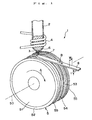
- Fig. 1 is a perspective view which schematically shows an apparatus provided with a cooling roll (melt spinning apparatus) for manufacturing a ribbon - shaped magnetic material, which is used in a first embodiment of the manufacturing method of the present invention.
- a cooling roll melt spinning apparatus
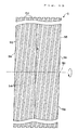
- Fig. 2 is a front view of the cooling roll shown in Fig. 1.
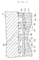
- Fig. 3 is a sectional view which schematically shows the structure of a portion in the vicinity of the circumferential surface of the cooling roll shown in Fig. 1.
- Fig. 4 is a cross-sectional view which schematically shows the situation caused in the vicinity of the colliding section of the molten alloy with respect to the cooling roll of the melt spinning apparatus shown in Fig. 1.
- Fig. 5 is an illustration for explaining a method of forming a gas flow passage.
- Fig. 6 is an illustration for explaining another method of forming the gas flow passage.
- Fig. 7 is an illustration which schematically shows one example of the composite structure (nanocomposite structure) of the magnetic powder of the present invention.
- Fig. 8 is an illustration which schematically shows another example of the composite structure (nanocomposite structure) of the magnetic powder of the present invention.
- Fig. 9 is an illustration which schematically shows the other example of the composite structure (nanocomposite structure) of the magnetic powder of the present invention.
- Fig. 10 is a perspective view which schematically shows a surface condition of a melt spun ribbon manufactured by the melt spinning apparatus shown in Fig. 1.
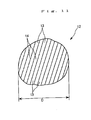
- Fig. 11 is a perspective view which schematically shows a surface condition of a particle of magnetic powder which is obtained by milling the melt spun ribbon manufactured by the melt spinning apparatus shown in Fig. 1.
- Fig. 12 is a front view which schematically shows a cooling roll used in a second embodiment of the manufacturing method according to the present invention.
- Fig. 13 is a sectional view which schematically shows the structure of a portion in the vicinity of the circumferential surface of the cooling roll shown in Fig. 12.
- Fig. 14 is a front view which schematically shows a cooling roll used in a third embodiment of the manufacturing method according to the present invention.
- Fig. 15 is a sectional view which schematically shows the structure of a portion in the vicinity of the circumferential surface of the cooling roll shown in Fig. 14.
- Fig. 16 is a front view which schematically shows a cooling roll used in a fourth embodiment of the manufacturing method according to the present invention.
- Fig. 17 is a sectional view which schematically shows the structure of a portion in the vicinity of the circumferential surface of the cooling roll of the fourth embodiment of the present invention.
- Fig. 18 is a sectional view which schematically shows a cooling roll used in other embodiment of the manufacturing method of the present invention.
- Fig. 19 is an illustration which schematically shows one variation of a gas flow passage formed in a circumferential surface of a cooling roll used the manufacturing method of the present invention.
- Fig. 20 is an illustration which schematically shows another variation of the gas flow passage formed in a circumferential surface of a cooling roll used in the manufacturing method of the present invention.
- Fig. 21 is a sectional side view which schematically shows the situation caused at or around a colliding section of a molten alloy with a cooling roll in the conventional melt spinning apparatus which manufactures a ribbon-shaped magnetic material using a single roll method.
- Fig. 1 is a perspective view showing an apparatus (a melt spinning apparatus) used in the first embodiment of the manufacturing method of the present invention
- Fig. 2 is a front view of a cooling roll used in the melt spinning apparatus shown in Fig. 1
- Fig. 3 is an enlarged cross sectional view of a portion of the cooling roll shown in Fig. 2.
- the magnetic powder of the present invention is obtained by milling a ribbon-shaped magnetic material (hereinafter, referred to as a "melt spun ribbon") which has been manufactured by the melt spinning apparatus as shown in Fig. 1. Therefore, a description will be first made with regard to the structure of the melt spinning apparatus.
- the melt spinning apparatus 1 includes a cylindrical body 2 capable of receiving a magnetic material, and a cooling roll 5 which rotates in the direction of an arrow A in the figure relative to the cylindrical body 2.
- a nozzle (orifice) 3 which injects a molten alloy 6 of a magnetic material is formed at the lower end of the cylindrical body 2.
- the cylindrical body 2 may be formed of a heat resistance ceramic material such as crystal, alumina, magnesia and the like.
- the nozzle opening of the nozzle 3 may be formed into various shapes such as circle, ellipse, slit and the like.
- a heating coil 4 By applying high frequency wave to the coil 4. for example, the inside of the cylindrical body 2 is heated (inductively heated) and therefore the magnetic material in the cylindrical body 2 becomes a melting state.
- the heating means used in this apparatus is not limited to the coil 4 described above, and a carbon heater may be employed instead of the coil 4, for example.
- the cooling roll 5 is constructed from a roll base 51 and a surface layer 52 which constitutes a circumferential surface 53 of the cooling roll 5.
- the material used for the roll base 51 is not limited to a specific material. However, in the present invention, it is preferred that the roll base 51 is formed of a metal material having high heat conductivity such as copper or copper alloys in order to make it possible to dissipate heat generated in the surface layer 52 as quickly as possible.
- the surface layer 52 may be formed of the same material as that for the roll base 51. However, it is preferred that the surface layer 52 is formed of a material having lower heat conductivity than that of the material for the roll base 51. In this case, it is preferable that the heat conductivity of the structural material of the surface layer at or around a room temperature is equal to or less than 80W ⁇ m -1 ⁇ K -1 , it is more preferable that the heat conductivity lies within the range of 3 to 60W ⁇ m -1 ⁇ K -1 , and it is the most preferable that the heat conductivity lies within the range of 5 to 40W ⁇ m -1 ⁇ K -1 .
- Examples of the materials having such heat conductivity include metal materials such as Zr, Sb, Ti, Ta, Pd, Pt and alloys of these metals, metallic oxides of these metals, and ceramics.
- Examples of the ceramics include oxide ceramics such as Al 2 O 3 , SiO 2 , TiO 2 .
- nitride ceramics such as AlN, Si 3 N 4 , TiN, BN, ZrN, HfN, VN, TaN, NbN, CrN, Cr 2 N and the like; carbide ceramics such as graphite, SiC, ZrC, Al 4 C 3 , CaC 2 , WC, TiC, HfC, VC, TaC, NbC and the like; and mixture of two or more of these ceramics.
- materials containing nitride ceramics are particularly preferred.
- the cooling roll 5 By constructing the cooling roll 5 from the surface layer 52 and the roll base 51 each having the heat conductivity as described above, it becomes possible to quench the molten alloy 6 in an appropriate cooling rate. Further, the difference between the cooling rates at the vicinity of the roll contact surface 81 (which is the surface of the melt spun ribbon to be in contact with the circumferential surface of the cooling roll) and at the vicinity of the free surface 82 (which is a surface of the melt spun ribbon opposite to the roll contact surface) becomes small. Consequently, it is possible to obtain a melt spun ribbon 8 having less dispersion in its crystal grain sizes at various portions thereof so as to have excellent magnetic properties.
- melt spun ribbon 8 is comprised of particles each having less dispersion in its crystal grain sizes, so that dispersion in their magnetic properties can be made small. As a result, it becomes possible for the magnetic powder to have excellent magnetic properties as a whole.
- these ceramics As compared with the conventional materials used for constituting the circumferential surface of the cooling roll (that is, Cu, Cr or the like), these ceramics have high hardness and excellent durability (anti-abrasion characteristic). Therefore, even if the cooling roll 5 is repeatedly used, the shape of the circumferential surface 53 can be maintained, and therefore the effect of the gas expelling means (described later) will be scarcely deteriorated.
- the materials which can be used for the cooling roll 51 described above have high coefficient of thermal expansion. Therefore, it is preferred that the coefficient of thermal expansion of the material of the surface layer 52 is close to that of the material of the roll base 51.
- the coefficient of thermal expansion (coefficient of linear expansion ⁇ ) at or around a room temperature is preferably in the range of 3.5 to 18[ ⁇ 10 -6 K -1 ], and more preferably in the range of 6 to 12[ ⁇ 10 -6 K -1 ].
- coefficient of thermal expansion of the material of the surface layer 52 at or around a room temperature (hereinafter, simply referred to as "coefficient of thermal expansion") lies within this range, it is possible to maintain reliable bonding between the roll base 51 and the surface layer 52, thereby enabling to prevent peeling-off of the surface layer 52 effectively.
- the composition of the material of the surface layer it is not necessary for the composition of the material of the surface layer to have uniform distribution in the thickness direction thereof.
- the contents of the constituents may be gradually changed in the thickness direction thereof (that is, graded materials may be used).
- the average thickness of the surface layer 52 (in the case of the laminate structure, the total thickness thereof) is not limited to a specific value. However, it is preferred that the average thickness lies within the range of 0.5 - 50 ⁇ m, and more preferably 1 - 20 ⁇ m.
- the average thickness of the surface layer 52 is less than the lower limit value described above, there is a possibility that the following problems will be raised. Namely, depending on the material to be used for the surface layer 52, there is a case that cooling ability becomes too high. When such a material is used for the surface layer 52, a cooling rate becomes too large in the vicinity of the roll contact surface 81 of the melt spun ribbon 8 even though it has a considerably large thickness, thus resulting in the case that amorphous structure is liable to be produced at that portion. On the other hand, in the vicinity of the free surface 82 of the melt spun ribbon 8, the cooling rate becomes small as the thickness of the melt spun ribbon 8 increases, so that crystal grain size is liable to be coarse.
- the use of the cooling roll having the surface layer of which average thickness is less than the lower limit value leads to the case that the crystal grain size is liable to be coarse in the vicinity of the free surface 82 of the obtained melt spun ribbon 8 and that amorphous structure is liable to be produced in the vicinity of the roll contact surface 81 of the melt spun ribbon 8, which results in the case that satisfactory magnetic properties can not be obtained even if such a melt spun ribbon will be subjected to a heat treatment at the later stage.
- melt spun ribbon 8 even if the thickness of the melt spun ribbon 8 is made small by increasing the peripheral velocity of the cooling roll 5, for example, in order to reduce the crystal grain size in the vicinity of the free surface 82 of the melt spun ribbon 8, this in turn leads to the case that the melt spun ribbon 8 has more random amorphous structure in the vicinity of the roll contact surface 81 of the obtained melt spun ribbon 8. In such a melt spun ribbon 8, there is a case that sufficient magnetic properties can not be obtained even if it is subjected to a heat treatment after manufacturing thereof.
- the method for forming the surface layer 52 is not limited to a specific method. However, it is preferable to employ a chemical vapor deposition (CVD) method such as heat CVD, plasma CVD, and laser CVD and the like, or a physical vapor deposition method (PVD) such as vapor deposition, spattering and ion-plating and the like. According to these methods, it is possible to obtain a surface layer having an uniform thickness with relative ease, so that it is not necessary to perform machining work onto the surface thereof after formation of the surface layer 52. Further, the surface layer 52 may be formed by means of other methods such as electro plating, immersion plating, elecroless plating, and metal spraying and the like. Among these methods, the metal spraying is particularly preferred. This is because when the surface layer 52 is formed by means of the metal spraying method, the surface layer 52 can be firmly adhered or bonded to the roll base 51.
- CVD chemical vapor deposition
- PVD physical vapor deposition method
- gas flow passages in the form of grooves 54 which function as gas expelling means for expelling gas that has entered between the circumferential surface 53 and a puddle 7 of the molten alloy 6.
- the puddle 7 becomes capable of more reliably contacting with the circumferential surface 53 (this prevents formation of huge dimples).
- magnetic powder obtained by milling the melt spun ribbon 8 is comprised of or contains particles each having small dispersion in its crystal grain sizes, and therefore dispersion in its magnetic properties also becomes small. For these reasons, magnetic powder having excellent magnetic properties as a whole can be obtained.
- melt spun ribbon 8 can have especially excellent magnetic properties with less dispersion at various portions thereof. Therefore, by using the melt spun ribbon 8, it is possible to obtain magnets having especially excellent magnetic properties.
- the gas flow passages (grooves) 54 are arranged substantially in parallel with the rotational direction of the cooling roll.
- gas which has been fed into the gas flow passages 54 can be expelled along the longitudinal direction of each gas flow passage 54. Therefore, gas which has entered between the circumferential surface 53 and the puddle 7 can be expelled with a particularly high efficiency, thus resulting in improved contact of the puddle 7 with the circumferential surface 53.
- cooling roll shown in the drawings has a plurality of gas flow passages, at least one passage is sufficient in this invention.
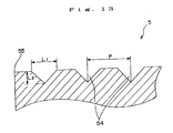
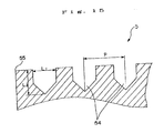
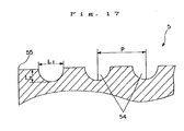
- the average value L 1 of the width of the gas flow passages 54 (at a portion opening to the circumferential surface 53) is preferably set to be 0.5 - 90 ⁇ m, more preferably 1 - 50 ⁇ m, and most preferably 3 - 25 ⁇ m. If the average width L 1 of the gas flow passages 54 is less than the smallest value, there is a case that gas which has entered between the circumferential surface 53 and the puddle 7 can not be sufficiently expelled. On the other hand, if the average width L 1 of the gas flow passages 54 exceeds the largest value, there is a case that the molten alloy 6 enters into the gas flow passages 54 so that the gas flow passages 54 will not function as the gas expelling means.
- the average value L 2 of the depth (maximum depth) of the gas flow passages 54 is preferably set to be 0.5 - 20 ⁇ m, and more preferably 1 - 10 ⁇ m. If the average depth L 2 of the gas flow passages 54 is less than the smallest value, there is a case that gas which has entered between the circumferential surface 53 and the puddle 7 can not be sufficiently expelled. On the other hand, if the average depth L 2 of the gas flow passages 54 exceeds the largest value, the flow rate of the gas flowing in the gas flow passages increases so that the gas flow tends to be turbulent flow with eddies, which results in the case that huge dimples are liable to be formed in the roll contact surface of the melt spun ribbon 8.
- the average width L 1 of the gas flow passages 54 and the average depth L 2 of the gas flow passages 54 satisfy the following equation (I). 0.5 ⁇ L 1 /L 2 ⁇ 15
- the average width L 1 and the average depth L 2 satisfy the following equation (II), and it is further more preferable that they satisfy the following equation (III).
- the average pitch P[ ⁇ m] of the adjacent gas flow passages arranged in parallel with each other should satisfy the following relationship with respect to the average particle size (diameter) D[ ⁇ m] of the particles of the magnetic powder (which will be described later in more detail with reference to the section entitled as "Manufacture of Magnetic Powder”).
- the average pitch P of the adjacent gas flow passages 54 is not limited to a particular value. But it is preferable that the average pitch is in the range of 0.5 - 100 ⁇ m, and it is more preferable that it is in the range of 3 - 50 ⁇ m. If the average pitch is within these ranges, each gas flow passage 54 effectively functions as the gas expelling means, and the interval between the contacting portion and the non-contacting portion of the puddle 7 with respect to the circumferential surface 53 can be made sufficiently small. With this result, the difference in the cooling rates at the contacting portion and the non-contacting portion becomes sufficiently small, so that it is possible to obtain amelt spun ribbon 8 having small dispersion in its grain sizes and magnetic properties .
- the surface layer 52 is made of the ceramics as described above, deterioration of the surface condition of the surface layer 52 such as abrasion or chipping of the surface layer will hardly occur even if the gas flow passages 54 with the small pitch therebetween are formed in the surface layer 52. Therefore, even if the cooling roll 5 is repeatedly used, the effect of the gas expelling means can be maintained.
- the ratio of the area of the gas flow passages 54 with respect to the area of the circumferential surface 53 when they are projected on the same plane is preferably set to be 10-99.5%, and more preferably 30 - 95%. If the ratio of the projected area of the gas flow passages with respect to the projected area of the circumferential surface 53 is less than the lower limit value, the cooling rate of the melt spun ribbon 8 in the vicinity of its roll contact surface 81 thereof becomes large so that such a portion is liable to have an amorphous structure. Further, in the vicinity of the free surface 82 of the melt spun ribbon 8, the crystal grain size becomes coarse due to the relatively lower cooling rate therein as compared with that in the vicinity of the roll contact surface 81, thus leading to the case that magnetic properties are lowered.
- Fig. 4 is a cross-sectional view which schematically shows the situation caused in the vicinity of the colliding section of the molten alloy with respect to the cooling roll of the melt spinning apparatus shown in Fig. 1.
- the arrows indicate main paths of heat conduction caused in the vicinity of the cooling roll 5.
- the heat absorbed by the surface layer 52 in this way is transmitted to the roll base 51.
- the heat transmission to the roll base 51 is mainly achieved by the heat generated from the portions 521.
- the roll base 51 and the surface layer 52 are formed of the materials as described above, the roll base 51 normally has higher heat conductivity than that of the surface layer 52.
- the heat transmitted from the portions 521 to portions 511 of the roll base 51 is then transmitted to adjacent portions 512 of the roll base 51 immediately.
- dispersion of temperatures at these portions 511 and 512 is made small, so that a temperature rise in the roll base 51 is moderated as a whole.
- thermal expansion occurring in the roll base 51 becomes small, so that difference between the thermal expansion of the surface layer 52 and the thermal expansion of the roll base 51 is made small. As a result, the firm bonding between the surface layer 52 and the roll base 51 can be maintained.
- the surface roughness Ra of the circumferential surface 53 other than the portions in which the gas flow passages 54 are formed is not limited to a particular value , but it is preferred that the surface roughness Ra is in the range of 0.05 - 5 ⁇ m, and more preferably 0.07 - 2 ⁇ m. If the surface roughness Ra is lower than the lower limit value, the puddle 7 can not be sufficiently in contact with the cooling roll 5, which results in the case that formation of huge dimples can not be suppressed effectively. On the other hand, if the surface roughness Ra exceeds the upper limit value, dispersion in the thickness of the melt spun ribbon 8 becomes prominent, so that there is a possibility that dispersion in the crystal grain sizes and dispersion in the magnetic properties become large.
- Fig. 3 is a sectional view which schematically shows the structure of a portion in the vicinity of the circumferential surface of the cooling roll, but in this figure a boundary surface between the roll base 51 and the surface layer 52 is omitted (this is the same as Figs. 13, 15, 17, 19 and 20 described hereinbelows).
- Various methods can be used for forming the gas flow passages 54.
- the methods include various machining processes such as cutting, transfer (pressure rolling), gliding, blasting and the like, laser processing, electrical discharge machining, and chemical etching and the like.
- the machining process, especially gliding is particularly preferred, since according to the gliding the width and depth of each gas flow passage and the pitch of the adjacent gas flow passages can be relatively easily adjusted with high precision as compared with other methods.
- the gas flow passages (grooves) 54 are normally formed in the surface layer 52, but other method may be used for forming the gas flow passages. Namely, as shown in Fig. 5, normally, after formation of the surface layer 52, the gas flow passages 54 are formed by any one of the gas flow passage forming methods mentioned above. However, as shown in Fig. 6, it is also possible to first form gas flow passages 54 onto the circumferential surface of the roll base 51 by any one of the gas flow passage forming methods mentioned above, and then to form a surface layer 52 thereon. According to this method, the gas flow passages 54 acting as the gas expelling means can be formed in the circumferential surface 53 without performing any machining process onto the surface layer 52. In this case, since no machining process is performed onto the surface layer 52, the surface roughness Ra of the circumferential surface 53 can be made small without performing polishing or the like at the later stage.
- the magnetic powder has excellent magnetic properties.
- the magnetic powder is preferably formed from alloys containing R (here, R is at least one of rare-earth elements containing Y).
- R is at least one of rare-earth elements containing Y.
- alloys containing R, TM (here, TM is at least one of transition metals) and B (Boron) are particularly preferred. In this case, any one of the following alloys is preferably used.
- Sm-Co based alloys include SmCo 5 , Sm 2 TM 17 (here, TM is a transition metal).
- R-Fe-B based alloys include Nd-Fe-B based alloys, Pr-Fe-B based alloys, Nd-Pr-Fe-B based alloys, Nd-Dy-Fe-B based alloys, Ce-Nd-Fe-B based alloys, Ce-Pr-Nd-Fe-B based alloys, and one of these alloys in which a part of Fe is replaced with other transition metal such as Co or Ni or the like.
- Sm-Fe-N based alloys include Sm 2 Fe 17 N 3 which is formed by nitrifying a Sm 2 Fe 17 alloy and Sm-Zr-Fe-Co-N based alloys having a TbCu 7 phase as its main phase.
- N is introduced with the form of interstitial atom by subjecting the melt spun ribbon to an appropriate heat treatment to nitrify it after the melt spun ribbon has been manufactured.
- examples of the rare-earth elements mentioned above include Y, La, Ce, Pr, Nd, Pm, Sm, Eu, Gd, Tb, Dy, Ho, Er, Tm, Yb, Lu, and a misch metal, and one or more of these rare-earth metals may be contained.
- examples of the transition metals include Fe, Co, Ni and the like, and one or more of these metals may be contained.
- the magnetic materials may contain Al, Cu, Ga, Si, Ti, V, Ta, Zr, Nb, Mo, Hf, Ag, Zn, P, Ge, Cr and W, as needed.
- a soft magnetic phase 10 and a hard magnetic phase 11 exist with a pattern (model) as shown in, for example, Fig. 7, Fig; 8 or Fig.9, in which the thickness of the respective phases and the grain sizes therein are on the order of nanometers. Further, the soft magnetic phase 10 and the hard magnetic phase 11 are arranged adjacent to each other (this also includes the case where these phases are adjacent through intergranular boundary phase), which makes it possible to perform magnetic exchange interaction therebetween.
- the magnetization of the soft magnetic phase readily changes its orientation by the action of an external magnetic field. Therefore, when the soft magnetic phase coexists with the hard magnetic phase, the magnetization curve for the entire system shows a stepped "serpentine curve" in the second quadrant of the B-H diagram (J-Hdiagram).
- J-Hdiagram the B-H diagram
- a magnet having such a composite structure has mainly the following five features.
- magnets composed of the composite structure have excellent magnetic properties. Therefore, it is preferred that the magnetic powders according to the present invention have such a composite structure.
- the ribbon-shaped magnetic material is manufactured by colliding a molten alloy of a magnetic material onto the circumferential surface of the cooling roll to cool and then solidify it.
- a molten alloy of a magnetic material onto the circumferential surface of the cooling roll to cool and then solidify it.
- Fig. 10 is a perspective view which schematically shows a surface condition of a melt spun ribbon manufactured by the melt spinning apparatus shown in Fig. 1.
- Such a melt spinning apparatus shown in Fig. 1 is installed in a chamber (not shown), and it is operated under the condition that the interior of the chamber is filled with an inert gas or other kind of ambient gas.
- the ambient gas is an inert gas.
- examples of such an inert gas include argon gas, helium gas, nitrogen gas or the like.
- the pressure of the ambient gas is not particularly limited to a specific value, but 1 - 760Torr is preferable.
- a predetermined pressure which is higher than the internal pressure of the chamber is applied to the surface of the liquid of the molten alloy 6 in the cylindrical body 2.
- the molten alloy 6 is injected from the nozzle 3 by the differential pressure between the pressure of the ambient gas in the chamber and the summed pressure of the pressure applied to the surface of the liquid of the molten alloy 6 in the cylindrical body 2 and the pressure exerted in the cylindrical body 2 in proportion to the liquid level.
- the molten alloy injecting pressure (that is, the differential pressure between the pressure of the ambient gas in the chamber and the summed pressure of the pressure applied to the surface of the liquid of the molten alloy 6 in the cylindrical body 2 and the pressure exerted in the cylindrical body 2 in proportion to the liquid level) is not particularly limited to a specific value, but 10 - 100kPa is preferable.
- a magnetic material (alloy) is placed in the cylindrical body 2 and melted by heating with the coil 4, and then the molten alloy 6 is injected from the nozzle 3. Then, as shown in Fig. 1, the molten alloy 6 collides with the circumferential surface 53 of the cooling roll 5, and after the formation of a puddle 7, the molten alloy 6 is cooled down rapidly to be solidified while being dragged along the circumferential surface 53 of the rotating cooling roll 5, thereby forming a melt spun ribbon 8 in a continuous or intermittent manner. Under the situation, gas which has entered between the puddle 7 and the circumferential surface 53 is expelled or discharged to the outside through the gas flow passages 54. The roll contact surface 81 of the melt spun ribbon 8 thus formed is soon released from the circumferential surface 53, and the melt spun ribbon 8 proceeds in the direction of an arrow B in Fig. 1.
- the gas flow passages 54 are provided in the circumferential surface 53, the puddle 7 can be reliably in contact with the circumferential surface 53 to prevent formation of huge dimples. Further, ununiform cooling of the puddle 7 is also prevented. As a result, it is possible to obtain a melt spun ribbon 8 having high magnetic properties.
- the optimum range of the peripheral velocity of the cooling roll 5 depends upon the composition of the molten alloy, the structural material (composition) of the surface layer 52, and the surface condition of the circumferential surface 53 (especially, the wettability of the surface layer 52 with respect to the molten alloy 6), and the like.
- a peripheral velocity in the range of 5 to 60m/s is normally preferable, and 10 to 40m/s is more preferable. If the peripheral velocity of the cooling roll 5 is less than the above lower limit value, the cooling rate of the molten alloy 6 is decreased. This tends to increase the crystal grain size, thus leading to the case that the magnetic properties are lowered.
- melt spun ribbon 8 has uniform width w and thickness t.
- the average thickness t of the melt spun ribbon 8 should preferably lie in the range of 8 - 50 ⁇ m and more preferably lie in the range of 10 - 40 ⁇ m. If the average thickness t is less than the lower limit value, amorphous structure becomes dominant, so that there is a case that the magnetic properties can not be sufficiently improved even if a heat treatment is given in the later stage. Further, productivity per an unit time is also lowered. On the other hand, if the average thickness t exceeds the above upper limit value, the crystal grain size at the side of the roll contact surface 81 of the melt spun ribbon 8 tends to be coarse, so that there is a case that the magnetic properties are lowered.
- the obtained melt spun ribbon 8 may be subjected to at least one heat treatment for the purpose of, for example, acceleration of recrystallization of the amorphous structure and homogenization of the structure.
- the conditions of this heat treatment may be, for example, a heating at a temperature of 400 to 900°C for 0.5 to 300 min.
- this heat treatment is performed in a vacuum or under a reduced pressure (for example, in the range of 1 ⁇ 10 -1 to 1 ⁇ 10 -6 Torr), or in a nonoxidizing atmosphere of an inert gas such as nitrogen gas, argon gas, helium gas or the like.
- melt spun ribbon (ribbon-shaped magnetic material) 8 has a microcrystalline structure or a structure in which microcrystals are included in an amorphous structure, and exhibits excellent magnetic properties.
- At least a part of the roll contact surface 81 of the melt spun ribbon 8 is formed with a pattern which is produced by transfer of the shape or form of the circumferential surface 53 of the cooling roll 5.
- at least a part of the roll contact surface 81 of the melt spun ribbon 8 is formed with ridges 83 or recesses 84 which correspond to the shape or form of the circumferential surface 53 of the cooling roll 5.
- a binding resin enters recesses (spaces between the ridges) of particles of the magnetic powder. Accordingly, a bonding strength between the magnetic powder and the binding resin is increased, so that a high mechanical strength can be obtained with a relatively small amount of the binding resin.
- the bonded magnet can contain a relatively large amount of magnetic powder, and therefore have especially excellent magnetic properties.
- the magnetic powder can be sufficiently in contact with the binding resin during the kneading process thereof (that is, wettability is increased). Therefore, in the compound obtained by kneading the magnetic powder and the binding resin, the biding resin is adapted to cover the periphery of each particle of the magnetic powder, so that good moldability can be obtained with a relatively small amount of the binding resin.
- the average crystal grain size is preferably equal to or less than 500nm, more preferably equal to or less than 200nm, and most preferably lies in the range of 10 - 120nm. If the average crystal grain size exceeds 500nm, there is a case that magnetic properties, especially coercive force and rectangularity can not be sufficiently improved.
- the average crystal grain size of the soft magnetic phase 10 and hard magnetic phase 11 should preferably lie in the range of 1 - 100nm, and more preferably lie in the range of 5 - 50nm.
- the average crystal grain size lies in this range, more effective magnetic exchange interaction occurs between the soft magnetic phase 10 and the hard magnetic phase 11, so that markedly improved magnetic properties can be recognized.
- the average crystal grain size of the hard magnetic phase 11 near the roll contact surface 81 is defined as D1h
- the average crystal grain size of the soft magnetic phase 10 near the roll contact surface 81 is defined as D1s
- the average crystal grain size of the hard magnetic phase 11 near the free surface 82 is defined as D2h
- the average crystal grain size of the soft magnetic phase 10 near the free surface 82 is defined as D2s
- the value of D1h/D2h or D1s/D2s is in the range of 0.5 - 1.5, the difference between the crystal grain size near the roll contact surface 81 and the crystal grain size near the free surface 82 is small in both the hard magnetic phase 11 and the soft magnetic phase 10.
- magnetic powder has uniform magnetic properties, and therefore bonded magnets having excellent magnetic properties can be obtained.
- the bonded magnets can have high magnetic energy product (BH) max as well as excellent rectangularity in its hysteresis loop. As a result, the absolute value of the irreversible flux loss is made small, thus improving the reliability of the bonded magnets.
- the description was made with reference to the single roll method.
- twin roll method ridges or recesses as described above can be formed on the opposite surfaces of the obtained melt spun ribbon, respectively.
- the metallic structure that is, crystal grain
- these methods are particularly effective in improving magnetic properties of bonded magnets, especially coercive force thereof.
- Fig. 11 is a perspective view which schematically shows a surface condition of a particle of magnetic powder which is obtained by milling the melt spun ribbon manufactured by the melt spinning apparatus shown in Fig. 1.
- the milling method of the melt spun ribbon is not particularly limited, and various kinds of milling or crushing apparatus such as ball mill, vibration mill, jet mill, and pin mill may be employed.
- the milling process may be carried out in vacuum or under a reduced pressure (for example, under a reduced pressure of 1 ⁇ 10 -1 to 1 ⁇ 10 -6 Torr), or in a nonoxidizing atmosphere of an inert gas such as nitrogen, argon, helium, or the like.
- the average size D[ ⁇ m] of the particles of the magnetic powder is determined so as to have the following relationship with respect to the average pitch P[ ⁇ m]. P ⁇ D
- the value D of the average particle size of the magnetic powder 12 should lie in the range of 5 to 300 ⁇ m, and preferably lie in the range of 10 to 20 ⁇ m from the view points of preventing oxidization of the magnetic powder and preventing deterioration of the magnetic properties during the milling process.
- the bonded magnets In order to obtain a better moldability during the manufacturing process of the bonded magnets, it is preferable to give a certain degree of dispersion to the particle size distribution of the magnetic powder. By so doing, it is possible to reduce the void ratio (porosity) of the bonded magnet obtained. As a result, it is possible to increase the density and the mechanical strength of the bonded magnet as compared with a bonded magnet having the same content of the magnetic powder, thereby enabling to further improve the magnetic properties.
- the average diameter D can be measured by a F.S.S.S. (Fischer Sub-Sieve Sizer) method or a sieving method and the like.
- the obtained magnetic powder is comprised of particles of which surfaces are formed with a number of ridges 13 or recesses 14.
- a binding resin is adapted to enter the recesses or (gaps between the ridges). This improves bonding strength between the magnetic powder and the binding resin, so that it becomes possible to obtain bonded magnets having high mechanical strength with use of a relatively small amount of a binding resin. Further, this in turn means that the obtained bonded magnets can contain a relatively large amount of magnetic powder, so that it is possible to obtain bonded magnets having especially excellent magnetic properties.
- the magnetic powder can be sufficiently in contact with the binding resin during the kneading process thereof (that is, wettability is increased). Therefore, in the compound obtained by kneading the magnetic powder and the binding resin, the biding resin is adapted to cover the periphery of each particle of the magnetic powder, so that good moldability can be obtained with use of a relatively small amount of the binding resin.
- the average particle size (diameter) of the magnetic powder is defined as D ⁇ m
- the length of the each recess or ridge is D/40 ⁇ m or more, and it is more preferable that the length is D/30 ⁇ m or more.
- the length of the recess or ridge is less than D/40 ⁇ m, there is a case that the effects of the present invention can not be sufficiently exhibited depending on the value of the average diameter D of the magnetic powder 12 or the like.
- the average height of the ridges 13 or the average depth of the recesses 14 is preferably 0.1 to 10 ⁇ m, and more preferably 0.3 to 5 ⁇ m.
- the average height of the ridges 13 or the average depth of the recesses 14 is in the rage described above, a necessary and large amount of the biding resin can enter the recesses or gaps between the ridges when the magnetic powder 12 is used for manufacturing bonded magnets, so that bonding strength between the magnetic powder and the binding resin is further improved, and therefore obtained bonded magnets can have further improved mechanical strength and magnetic properties.
- the average pitch of the adjacent two ridges 13 or recesses 14 is 0.5 - 100 ⁇ m, and more preferably 3 - 50 ⁇ m.
- the average pitch of the adjacent two ridges or recesses is within this range, the effects of the present invention described above are more conspicuous.
- a ratio of an area of the part of the particle of the magnetic powder where the ridges 13 or recesses 14 are formed with respect to the entire surface area of the particle is equal to or greater than 15%, and more preferably equal to or greater than 25%.
- the ratio of the area of the part of the particle where the ridges or recesses are formed with respect to the entire surface area of the particle is less than 15%, there is a case that the effects of the present invention described above are not sufficiently exhibited.
- magnétique powder may be subjected to a heat treatment for the purpose of, for example, removing the influence of stress introduced by the milling process and controlling the crystal grain size.
- the conditions of the heat treatment are, for example, heating at a temperature in the range of 350 to 850°C for 0.5 to 300 min.
- the heat treatment in a vacuum or under a reduced pressure (for example, in the range of 1 ⁇ 10 -1 to 1 ⁇ 10 -6 Torr), or in a nonoxidizing atmosphere of an inert gas such as nitrogen gas, argon gas, and helium gas.
- a vacuum or under a reduced pressure for example, in the range of 1 ⁇ 10 -1 to 1 ⁇ 10 -6 Torr
- an inert gas such as nitrogen gas, argon gas, and helium gas.
- magnetic powder can achieve a satisfactory binding with binding resins (wettability of binding resins). Therefore, when a bonded magnet is manufactured using the magnetic powder described above, the bonded magnet has high mechanical strength as well as excellent thermal stability (heat resistance) and corrosion resistance. Consequently, it can be concluded that the magnetic powder is suitable for the manufacture of a bonded magnet, and the manufactured bonded magnet has high reliability.
- the average crystal grain size of the magnetic powder should preferably be equal to or less than 500nm, more preferably equal to or less than 200nm, and most preferably lie in the range of 10 - 120nm. If the average crystal grain size exceeds 500nm, there is a case that magnetic properties, especially coercive force and rectangularity can not be sufficiently improved.
- the average crystal grain size should preferably lie in the range of 1 - 100nm, and more preferably lie in the range of 5 - 50nm.
- the average crystal grain size lies in this range, more effective magnetic exchange interaction occurs between the soft magnetic phase 10 and the hard magnetic phase 11, so that markedly improved magnetic properties can be recognized.
- the bonded magnet according to the present invention is manufactured by binding the magnetic powder described above using a binding resin (binder).
- thermoplastic resin either of a thermoplastic resin or a thermosetting resin may be employed.
- thermoplastic resin examples include polyamid (example: nylon 6, nylon 46, nylon 66, nylon 610, nylon 612, nylon 11, nylon 12, nylon 6-12, nylon 6-66); thermoplastic polyimide; liquid crystal polymer such as aromatic polyester; poly phenylene oxide; poly phenylene sulfide; polyolefin such as polyethylene, polypropylene and ethylene-vinyl acetate copolymer; modified polyolefin; polycarbonate; poly methyl methacrylate; polyester such as poly ethylen terephthalate and poly butylene terephthalate; polyether; polyether ether ketone; polyetherimide; polyacetal; and copolymer, blended body, and polymer alloy having at least one of these materials as a main ingredient. In this case, a mixture of two or more kinds of these materials may be employed.
- thermoplastic resins also have an excellent kneadability with the magnetic powder.
- thermoplastic resins provide an advantage in that awide range of selection can be made. For example, it is possible to provide a thermoplastic resin having a good moldability or to provide a thermoplastic resin having good heat resistance and mechanical strength by appropriately selecting their kinds, copolymerization or the like.
- thermosetting resin examples include various kinds of epoxy resins of bisphenol type, novolak type, and naphthalene-based, phenolic resins, urea resins, melamine resins, polyester (or unsaturated polyester) resins, polyimide resins, silicone resins, polyurethane resins, and the like. In this case, a mixture of two or more kinds of these materials may be employed.
- the epoxy resins are preferable from the viewpoint of their special excellence in the moldability, high mechanical strength, and high heat resistance.
- the epoxy resins are especially preferable.
- These thermosetting resins also have an excellent kneadability with the magnetic powder and homogeneity (uniformity) in kneading.
- the unhardened thermosetting resin to be used may be either in a liquid state or in a solid (powdery) state at a room temperature.
- the bonded magnet according to this invention described in the above may be manufactured, for example, as in the following.
- the magnetic powder, a binding resin and an additive (antioxidant, lubricant, or the like) as needed are mixed and kneaded to form a bonded magnet composite (compound).
- a molding method such as compaction molding (press molding), extrusion molding, or injection molding.
- the binding resin used is a thermosetting type
- the obtained green compact is hardened by heating or the like after molding.
- the kneading process may be carried out at a room temperature. However, it is preferred that the kneading is carried out at a temperature in which the used resin is begun to be soften or a higher temperature thereof. In particular, when the binding resin used is a thermosetting resin, it is preferred that the kneading is carried out at a temperature higher than a temperature in which the binding resin is begun to be softened and lower than a temperature in which the binding resin is begun to be hardened.
- the kneading efficiency is improved and the kneading is carried out uniformly in a shorter time as compared with the kneading at a room temperature.
- bindability between the magnetic powder and the binding resin is improved so that void ratio (porosity) of the compound can be made small.
- the softened or melted resin can enter the recesses or gaps between the ridges effectively.
- the void ratio can be further reduced. Further, this also contributes to reducing the amount of the binding resin to be contained in the compound.
- the molding according to any one of the molding methods is carried out at a temperature in which the binding resin is begun to be softened or melted (that is, warm kneading).
- the fluidity of the binding resin is improved, so that excellent moldability can be secured even in the case where a relatively small amount of the binding resin is used. Further, since the fluidity of the binding resin is improved, the binding resin becomes sufficiently and reliably in contact with the magnetic powder, so that void ratio of the bonded magnet can be made small.
- the binding resin which has been softened or melted effectively enters the recesses or the gaps between the ridges. With this result, the bonding strength between the magnetic powder and the binding resin is further improved, and the void ratio of the obtained bonded magnet can be made small, so that it is possible to manufacture a bonded magnet having a high density and excellent magnetic properties and mechanical strength.
- the indexes for indicating the mechanical strength is mechanical strength obtained by a shear strength by punching-out test known as "Testing Method of Measuring Shear Strength by Punching-out Small Specimen of Bonded Magnets" which is determined by the standard of Electronic Materials Manufactures Association of Japan under the code number of EMAS-7006.
- the mechanical strength of the bonded magnet according to this test should preferably be equal to or larger than 50MPa and more preferably be equal to or larger than 60MPa.
- the content of the magnetic powder in the bonded magnet is not particularly limited, and it is normally determined by considering the kind of the molding method to be employed and the compatibility of moldability and high magnetic properties. For example, it is preferred that the content is in the range of 75 - 99.5wt%, and more preferably in the range of 85 - 97.5wt%.
- the content of the magnetic powder should preferably lie in the range of 90 - 99.5wt%, and more preferably in the range of 93 - 98.5wt%.
- the content of the magnetic powder should preferably lie in the range of 75 - 98wt%, and more preferably in the range of 85 - 97wt%.
- the bonding strength between the magnetic powder and the binding resin becomes especially excellent. For this reason, high mechanical strength can be obtained even if a relatively small amount of the binding resin is used. As a result, it becomes possible to increase the amount of the magnetic powder to be contained, so that a bonded magnet having high magnetic properties can be obtained.
- the density ⁇ of the bonded magnet is determined by factors such as the specific gravity of the magnetic powder contained in the bonded magnet, the content of the magnetic powder, and the void ratio (porosity) of the bonded magnet and the like.
- the density ⁇ is not particularly limited to a specific value, but it is preferable to be in the range of 4.5 - 6.6Mg/m 3 , and more preferably in the range of 5.5 - 6.4Mg/m 3 .
- the shapes (forms), dimensions and the like of the bonded magnet are not particularly limited.
- the shape all shapes such as columnar shape, prism-like shape, cylindrical shape (annular shape), arched shape, plate-like shape, curved plate-like shape, and the like are acceptable.
- the dimensions all sizes starting from large-sized one to ultraminuaturized one are acceptable.
- the present invention is particularly advantageous when it is used for miniaturized magnets and ultraminiaturized magnets.
- the coercive force (H CJ ) (intrinsic coercive force at a room temperature) of the bonded magnet lies in the range of 320 to 1200kA/m, and more preferably in the range of 400 to 800kA/m. If the coercive force (H CJ ) is lower than the lower limit value, demagnetization occurs conspicuously when a reverse magnetic field is applied, and the heat resistance at a high temperature is deteriorated. On the other hand, if the coercive force (H CJ ) exceeds the above upper limit value, magnetizability is deteriorated.
- the maximum magnetic energy product (BH) max of the bonded magnet is equal to or greater than 40kJ/m 3 , more preferably equal to or greater than 50kJ/m 3 , and most preferably in the range of 70 to 130kJ/m 3 .
- the maximum magnetic energy product (BH) max is less than 40kJ/m 3 , it is not possible to obtain a sufficient torque when used for motors depending on the types and structures thereof.
- the cooling roll 5 which is used in the manufacturing method of the magnetic powder of the present invention is provided with the gas flow passages 54, the gas that has entered between the circumferential surface 53 and the puddle 7 can be expelled. This prevents the puddle 7 from being released (or lifted up) from the circumferential surface 53, so that the puddle 7 can be sufficiently and reliably in contact with the circumferential surface 53. With this result, it is possible to obtain a melt spun ribbon 8 having less dispersion in magnetic properties at various portions thereof and therefore having high magnetic properties.
- the average particle size D[ ⁇ m] of the particles of the magnetic powder obtained by milling the melt spun ribbon 8 satisfies the relationship P ⁇ D with respect to the average pitch P[ ⁇ m] of the gas flow passages 54, there is less dispersion of magnetic properties among the respective particles of the magnetic powder, thus the magnetic properties of the magnetic powder as a whole become excellent.
- the bonded magnet manufactured from the melt spun ribbon 8 can have excellent magnetic properties. Further, high magnetic properties can be obtained without pursing a high density when manufacturing bonded magnets. This means that the obtained bonded magnets can have improved moldability, dimensional accuracy, mechanical strength, corrosion resistance and heat resistance and the like.
- Fig. 12 is a front view which schematically shows a cooling roll used in the second embodiment of the magnetic powder manufacturing method of the present invention
- Fig. 13 is a sectional view which schematically shows the structure of a portion in the vicinity of the circumferential surface of the cooling roll 5 shown in Fig. 12.
- a description will be made with regard to the cooling roll 5 used in the second embodiment of the manufacturing method by focusing on different points between the cooling rolls of first and second embodiments, and explanation for the common points is omitted.
- the gas flow passages 54 are spirally formed with respect to the rotation axis 50 of the cooling roll 5.
- the gas flow passages 54 having such spiral forms can be formed relatively easily over the entire of the circumferential surface 53 .
- such gas flow passages 54 can be formed by cutting the outer circumferential portion of the cooling roll 5 with a cutting tool such as a lathe which is moved in a constant speed in parallel with the rotation axis 50 of the cooling roll 5 under the state that the cooling roll 5 is being rotated in a constant speed.
- the number of the spiral gas flow passages may be one or more.
- the angle ⁇ (absolute value) defined between the longitudinal direction of each gas flow passage 54 and the rotational direction of the cooling roll 5 should preferably be equal to or less than 30°, and more preferably equal to or less than 20°. If the angle ⁇ is equal to or less than 30°' the gas that has entered between the circumferential surface 53 and the puddle 7 can be expelled efficiently regardless of the peripheral velocity of the cooling roll 5.
- the angle ⁇ may be changed so as to have the same value or different values depending on locations on the circumferential surface 53. Further, when the two or more gas flow passages 54 are formed, the angle ⁇ may be changed in each of the gas flow passages 54.
- each gas flow passage 54 are formed into openings 56 opened at the opposite edge portions 55 of the circumferential surface 53 in the end surfaces of the cooling roll 5, respectively.
- This arrangement makes it possible to discharge the gas which has been expelled from between the circumferential surface 53 and the puddle 7 to the lateral sides of the cooling roll 5 through the openings 56, so that it is possible to effectively prevent the discharged gas from reentering between the circumferential surface 53 and the puddle 7 again.
- each gas flow passage 54 has the openings 56 at the opposite ends thereof, such an opening may be provided at one of the ends thereof.
- Fig. 14 is a front view which schematically shows a cooling roll used in the third embodiment of the magnetic powder manufacturing method of the present invention
- Fig. 15 is a sectional view which schematically shows the structure of a portion in the vicinity of the circumferential surface of the cooling roll 5 shown in Fig. 14.
- a description will be made with regard to the cooling roll 5 used in the third embodiment of the manufacturing method by focusing on different points between the cooling rolls of the third embodiment and the first and second embodiments, and explanation for the common points is omitted.
- the melt spun ribbon 8 receives laterally exerted force from the dextral spirals as well as laterally exerted force from the sinistral spirals and these forces are cancelled with each other. Therefore, the lateral movement of the melt spun ribbon 8 in Fig. 14 is suppressed so that the advancing direction of the melt spun ribbon 8 becomes stable.
- angles (absolute value) defined between each of the longitudinal directions of the gas flow passages 54 and the rotational direction of the cooling roll 5 are in the same range as that of the angle ⁇ described above with reference to the second embodiment.
- Fig. 16 is a front view which schematically shows a cooling roll 5 used in the fourth embodiment of the magnetic powder manufacturing method of the present invention
- Fig. 17 is a sectional view which schematically shows the structure of a portion in the vicinity of the circumferential surface of the cooling roll 5 shown in Fig. 16.
- a description will be made with regard to the cooling roll 5 of the fourth embodiment by focusing on different points between the fourth embodiment and the first, second and third embodiments, and explanation for the common points is omitted.
- a plurality of V-shaped gas flow passages each having a peak at the center of the axial direction of the cooling roll 5 and two extending grooves extending to the edges 55 of the circumferential surface 53.
- the melt spun ribbon 8 receives laterally exerted force from the grooves located at one side thereof as well as laterally exerted force from the grooves located at the other side thereof, and these forces are balanced with each other.
- the melt spun ribbon 8 is adapted to be positioned at the center of the cooling roll 5 in the axial direction thereof so that the advancing direction of the melt spun ribbon 8 is stable.
- the structure of the gas flow passages 54 is not limited to those of the embodiments.
- the gas flow passages 54 of the present invention can be formed from a number of separate short slanting grooves 54. Further, the cross sectional shape of each groove 54 may be formed into one shown in Fig. 19 or Fig. 20.
- Magnetic powders were manufactured according to each of the following the manufacturing conditions (No. 1 to No. 10).
- a roll base (having diameter of 200mm and width of 30mm) made of a copper (having heat conductivity of 395W ⁇ m -1 ⁇ K -1 at a temperature of 20°C and coefficient of thermal expansion (coefficient of linear expansion ⁇ ) of 16.5 ⁇ 10 -6 K -1 at a temperature of 20°C) was prepared, and then it was ground so as to have a mirror finishing outer circumferential surface with a surface roughness of Ra 0.07 ⁇ m.
- a surface layer of VN (a kind of ceramics) (having heat conductivity of 11.3W ⁇ m -1 ⁇ K -1 at a temperature of 20°C and coefficient of thermal expansion (coefficient of linear expansion ⁇ ) of 9.2 ⁇ 10 -6 K -1 at a temperature of 20°C) was formed onto the outer circumferential surface of the roll base by means of ion plating to obtain the cooling roll shown in Figs. 1 to 3.
- the thickness of the surface layer was 5 ⁇ m. Further, no machining work was performed for the surface layer after formation thereof.
- melt spun ribbons made of an alloy having an alloy composition represented by the formula of (Nd 0.77 Pr 0.18 Dy 0.05 ) 8.9 Fe bal. Co 8.2 B 5.5 were manufactured in accordance with the following method.
- the mother alloy ingot was put into a crystal tube having a nozzle (circular orifice) 3 at the bottom thereof of the melt spinning apparatus 1. Thereafter, a chamber in which the melt spinning apparatus 1 is installed was vacuumed, and then an inert gas (Helium gas) was introduced to create a desired atmosphere of predetermined temperature and pressure.
- an inert gas Helium gas
- the mother alloy ingot in the crystal tube was melt by heating it by means of high frequency inductive heating. Then, under the conditions that the peripheral velocity of the cooling roll 5 was set to be a predetermined velocity, the injection pressure (that is, the differential pressure between the ambient pressure and the summed pressure of the internal pressure of the crystal tube and the pressure applied to the surface of the liquid in the tube which is in proportion to the liquid level) of the molten alloy 6 was set to be 40kPa, and the pressure of the ambient gas was set to be 60kPa, the molten alloy 6 was injected toward the apex of the circumferential surface 53 of the cooling roll 5 from just above the rotational axis of the cooling roll 5, to manufacture a melt spun ribbon 8 in a continuous manner. In this case, several lots of melt spun ribbons were manufactured by changing the peripheral velocity of the cooling roll 5 in various ways.
- melt spun ribbons were subjected to a heat treatment in the argon gas atmosphere at a temperature of 680°C for 5 minutes. Then, the magnetic properties of each of the melt spun ribbons were measured using a vibrating sample magnetometer (VSM). In the measurement, the magnetic field was applied along the major axis of the respective melt spun ribbons. However, no demagnetization correction was performed. After the measurement of the magnetic properties of the melt spun ribbons, the lot of the melt spun ribbons having the most excellent magnetic properties was selected, and then the selected melt spun ribbons were milled and subjected to a heat treatment at a temperature of 650°C for 4 minutes, to obtain magnetic powders having the average particle size of 70 ⁇ m.
- VSM vibrating sample magnetometer
- a cooling roll B having the same configuration as that of the cooling roll A excepting that the shape and form of the grooves were formed into those shown in Figs. 12 and 13 was manufactured in accordance with the same manner.
- this cooling roll B the formation of the grooves was performed in the following manner. Namely, three sets of grooves were formed using a lathe having three cutting tools arranged so as to have the same interval so that the adjacent grooves
- melt spun ribbons were manufactured in the same manner as the manufacturing condition No. 1 excepting that the cooling roll B was used instead of the cooling roll A.
- melt spun ribbons were subjected to a heat treatment in the argon gas atmosphere at a temperature of 680°C for 5 minutes.
- the magnetic properties of each of the melt spun ribbons were measured in the same manner as the manufacturing condition No. 1.
- the lot of the melt spun ribbons having the most excellent magnetic properties was selected, and then the selected melt spun ribbons were milled and subjected to a heat treatment at a temperature of 650°C for 4 minutes, to obtain magnetic powders having the average particle size of 70 ⁇ m.
- a cooling roll C having the same configuration as that of the cooling roll B excepting that the shape and form of the grooves were formed into those shown in Figs. 14 and 15 was manufactured in accordance with the same manner.
- melt spun ribbons were manufactured in the same manner as the manufacturing condition No. 1 excepting that the cooling roll C was used instead of the cooling roll A.
- melt spun ribbons were subjected to a heat treatment in the argon gas atmosphere at a temperature of 680°C for 5minutes.
- the magnetic properties of each of the melt spun ribbons were measured in the same manner as the manufacturing condition No. 1.
- the lot of the melt spun ribbons having the most excellent magnetic properties was selected, and then the selected melt spun ribbons were milled and subjected to a heat treatment at a temperature of 650°C for 4 minutes, to obtain magnetic powders having the average particle size of 70 ⁇ m.
- a cooling roll D having the same configuration as that of the cooling roll B excepting that the shape and form of the grooves were formed into those shown in Figs. 16 and 17 was manufactured in accordance with the same manner.
- melt spun ribbons were manufactured in the same manner as the manufacturing condition No. 1 excepting that the cooling roll D was used instead of the cooling roll A.
- melt spun ribbons were subjected to a heat treatment in the argon gas atmosphere at a temperature of 680°C for 5minutes.
- the magnetic properties of each of the melt spun ribbons were measured in the same manner as the manufacturing condition No. 1.
- the lot of the melt spun ribbons having the most excellent magnetic properties was selected, and then the selected melt spun ribbons were milled and subjected to a heat treatment at a temperature of 650°C for 4 minutes, to obtain magnetic powders having the average particle size of 70 ⁇ m.
- a cooling roll E having the same configuration as that of the cooling roll B excepting that the structural material of the surface layer was TiN having heat conductivity of 29.4W ⁇ m -1 ⁇ K -1 at a temperature of 20°C and coefficient of thermal expansion (coefficient of linear expansion ⁇ ) of 9.3 ⁇ 10 -6 K -1 at a temperature of 20°C.
- melt spun ribbons were manufactured in the same manner as the manufacturing condition No. 1 excepting that the cooling roll E was used instead of the cooling roll A.
- melt spun ribbons were subjected to a heat treatment in the argon gas atmosphere at a temperature of 680°C for 5minutes.
- the magnetic properties of each of the melt spun ribbons were measured in the same manner as the manufacturing condition No. 1.
- a lot of the melt spun ribbons having the most excellent magnetic properties was selected, and then the selected melt spun ribbons were milled and subjected to a heat treatment at a temperature of 650°C for 4 minutes, to obtain magnetic powders having the average particle size of 70 ⁇ m.
- a cooling roll F having the same configuration as that of the cooling roll B excepting that the structural material of the surface layer was ZrN having heat conductivity of 16.8W ⁇ m -1 ⁇ K -1 at a temperature of 20°C and coefficient of thermal expansion (coefficient of linear expansion ⁇ ) of 7.2 ⁇ 10 -6 K -1 at a temperature of 20°C.
- melt spun ribbons were manufactured in the same manner as the manufacturing condition No. 1 excepting that the cooling roll F was used instead of the cooling roll A.
- melt spun ribbons were subjected to a heat treatment in the argon gas atmosphere at a temperature of 680°C for 5minutes.
- the magnetic properties of each of the melt spun ribbons were measured in the same manner as the manufacturing condition No. 1.
- a lot of the melt spun ribbons having the most excellent magnetic properties was selected, and then the selected melt spun ribbons were milled and subjected to a heat treatment at a temperature of 650°C for 4 minutes, to obtain magnetic powders having the average particle size of 70 ⁇ m.
- a cooling roll C having the same configuration as that of the cooling roll B excepting that the structural material of the surface layer was TiC having heat conductivity of 25.2W' m -1 ⁇ K -1 at a temperature of 20°C and coefficient of thermal expansion (coefficient of linear expansion ⁇ ) of 8.0 ⁇ 10 -6 K -1 at a temperature of 20°C.
- melt spun ribbons were manufactured in the same manner as the manufacturing condition No. 1 excepting that the cooling roll G was used instead of the cooling roll A.
- melt spun ribbons were subjected to a heat treatment in the argon gas atmosphere at a temperature of 680°C for 5minutes.
- the magnetic properties of each of the melt spun ribbons were measured in the same manner as the manufacturing condition No. 1.
- a lot of the melt spun ribbons having the most excellent magnetic properties was selected, and then the selected melt spun ribbons were milled and subjected to a heat treatment at a temperature of 650°C for 4 minutes, to obtain magnetic powders having the average particle size of 70 ⁇ m.
- melt spun ribbons were manufactured in the same manner as the manufacturing condition No. 1 excepting that the cooling roll H was used instead of the cooling roll A.
- melt spun ribbons were subjected to a heat treatment in the argon gas atmosphere at a temperature of 680°C for 5minutes.
- the magnetic properties of each of the melt spun ribbons were measured in the same manner as the manufacturing condition No. 1.
- a lot of the melt spun ribbons having the most excellent magnetic properties was selected, and then the selected melt spun ribbons were milled and subjected to a heat treatment at a temperature of 650°C for 4 minutes, to obtain magnetic powders having the average particle size of 70 ⁇ m.
- a roll base (having diameter of 200mm and width of 30mm) made of a copper (having heat conductivity of 395W ⁇ m -1 ⁇ K -1 at a temperature of 20°C and coefficient of thermal expansion (coefficient of linear expansion ⁇ ) of 16.5 ⁇ 10 -6 K -1 at a temperature of 20°C) was prepared, and then it was ground so as to have a mirror finishing outer circumferential surface with a surface roughness of Ra 0.07 ⁇ m.
- melt spun ribbons were manufactured in the same manner as the manufacturing condition No. 1 excepting that the cooling roll I was used instead of the cooling roll A.
- melt spun ribbons were subjected to a heat treatment in the argon gas atmosphere at a temperature of 680°C for 5minutes.
- the magnetic properties of each of the melt spun ribbons were measured in the same manner as the manufacturing condition No. 1.
- a lot of the melt spun ribbons having the most excellent magnetic properties was selected, and then the selected melt spun ribbons were milled and subjected to a heat treatment at a temperature of 650°C for 4 minutes, to obtain magnetic powders having the average particle size of 70 ⁇ m.
- a roll base (having diameter of 200mm and width of 30mm) made of a copper (having heat conductivity of 395W ⁇ m -1 ⁇ K -1 at a temperature of 20°C and coefficient of thermal expansion (coefficient of linear expansion ⁇ ) of 16.5 ⁇ 10 -6 K -1 at a temperature of 20°C) was prepared, and then it was ground so as to have a mirror finishing outer circumferential surface with a surface roughness of Ra 0.07 ⁇ m.
- melt spun ribbons were manufactured in the same manner as the manufacturing condition No. 1 excepting that the cooling roll J was used instead of the cooling roll A.
- melt spun ribbons were subjected to a heat treatment in the argon gas atmosphere at a temperature of 680°C for 5minutes.
- the magnetic properties of each of the melt spun ribbons were measured in the same manner as the manufacturing condition No. 1.
- a lot of the melt spun ribbons having the most excellent magnetic properties was selected, and then the selected melt spun ribbons were milled and subjected to a heat treatment at a temperature of 650°C for 4 minutes, to obtain magnetic powders having the average particle size of 70 ⁇ m.
- each of these cooling rolls used in the manufacturing conditions No. 1 to No. 10 the width L 1 of each gas flow passage (average value), the depth L 2 of each gas flow passage (average value), the pitch P (average value) of the adjacent gas flow passages, the angle ⁇ defined between the longitudinal direction of each gas flow passage and the rotational direction of the cooling roll, the ratio of the projected area of the gas flow passages with respect to the projected area of the circumferential surface of the cooling roll, and the surface roughness Ra of a part of the circumferential surface other than a part of the gas flow passages were measured, and the measured values thereof are shown in the attached TABLE 1.
- the peripheral velocity of the cooling roll at which the melt spun ribbons having the most excellent magnetic properties could be obtained is also shown.
- the height and length of the ridges formed on the surface of the particle and the pitch between the adjacent ridges were measured. Further, based on the observation results by the scanning electron microscope (SEM), a ratio of the area of a part of the surface of the particle where the ridges or recesses are formed with respect to the entire surface area of the particle was also obtained for each of the magnetic powders. These results are shown in the attached Table 2.
- the respective magnetic powders were subjected to an X-ray diffraction test using Cu-K ⁇ line at the diffraction angle (2 ⁇ ) of 20° - 60°.
- TEM transmission electron microscope
- each of the cooling rolls A to H used in the manufacturing conditions No. 1 to No. 8 had the gas flow passages acting as the gas expelling means on its circumferential surface. Therefore, in each of the manufacturing processes using these cooling rolls A to H, gas which entered between the puddle and the circumferential surface was effectively expelled so that the puddle could be sufficiently and reliably in contact with the circumferential surface, thereby enabling to prevent or suppress formation of huge dimples on the roll contact surface of the melt spun ribbon. Consequently, the difference in the cooling rates at the various portions of the melt spun ribbon can be made small.
- the average pitch P[ ⁇ m] of the gas flow passages formed on the circumferential surface was determined so as to satisfy the relationship of P ⁇ D with respect to the average particle size D[ ⁇ m] of the magnetic powder.
- the particles of the respective magnetic powder had small structural difference (that is, only small dispersion in their crystal grain sizes), and therefore dispersion in the magnetic properties was also small in each of the particles. It is believed that, for these reasons, each of the magnetic powders according to the present invention had improved magnetic properties as a whole as described above.
- the cooling roll I used in the manufacturing condition No. 9 had no gas flow passages on its circumferential surface. Therefore, in the manufacturing process using the cooling roll I, the puddle could not be sufficiently and reliably in contact with the circumferential surface of the cooling roll, so that gas was liable to enter between the puddle and the circumferential surface. In this melt spun ribbon, the gas which has entered between the puddle and the circumferential surface remained as it is to form huge dimples on the roll contact surface of the melt spun ribbon. Therefore, while a portion of the roll contact surface which was in contact with the circumferential surface had a relatively high cooling rate, a portion of the roll contact surface where such dimples were formed had a lower cooling rate so that the crystal grain size at that portion became coarse. It is believed that this causes the large dispersion in the magnetic properties of the obtained melt spun ribbon, and therefore the magnetic powder obtained by milling the melt spun ribbon had the poor magnetic properties as a whole.
- the cooling roll J used in the manufacturing condition No. 10 had the gas flow passages. Therefore, in the manufacturing process of the melt spun ribbon using the cooling roll J, it is believed that the puddle could be sufficiently and reliably in contact with the circumferential surface of the cooling roll.
- the average particle size D[ ⁇ m] of the magnetic powder was smaller than the average pitch P[ ⁇ m] of the gas flow passages, so that there were structural differences among the particles of the magnetic powder (that is, there was large dispersion in the crystal grain sizes of these particles). It is believed that this causes the large dispersion in the magnetic properties of the particles of the magnetic powder ribbon, and therefore the magnetic powder had the poor magnetic properties as a whole.
- each of the magnetic powders obtained in the Example 1 was mixed with an epoxy resin and a small amount of hydrazine-based antioxidant at a temperature of 100°C for 10 minutes, to obtain compositions for bonded magnets (compounds).
- the mixing ratio (parts by weight) of the magnetic powder, the epoxy resin and the hydrazine-based antioxidant was 97.5wt%, 1.3wt% and 1.2wt%, respectively.
- each of the thus obtained compounds was milled or crushed to be granular.
- the granular substance (particle) was weighed and filled into a die of a press machine, and then it was subjected to a compaction molding (in the absence of a magnetic field) at a temperature of 120°C and under the pressure of 600Mpa, to obtain a mold body.
- the epoxy resin was hardened by heating at a temperature of 175°C to obtain a bonded magnet of a columnar shape having a diameter of 10mm and a height of 7mm (for use in tests for measuring magnetic properties and heat resistance).
- a bonded magnet of a flat plate-shape having a cross section of 10mm x 10mm and a height of 7mm for use in test for measuring mechanical strength.
- a bonded magnet of a flat plate-shape having a cross section of 10mm x 10mm and a height of 7mm for use in test for measuring mechanical strength.
- the bonded magnets according to the manufacturing conditions No. 1 to No. 8 could be manufactured with good moldability.
- the bonded magnets by the manufacturing conditions No. 1 to No. 8 were manufactured using the magnetic powders obtained from the melt spun ribbons having excellent magnetic properties (with less dispersion thereof), respectively, the bonded magnets manufactured using these magnetic powders could have the excellent magnetic properties. Further, in each of these magnetic powders, the particles were formed with the ridges, and the recesses between the ridges were effectively filled with the binding resin when formed into the bonded magnet. Therefore, the bonding strength between the magnetic powder and the binding resin was increased, so that the high mechanical strength was obtained with the use of the relatively small amount of the binding resin. Further, the use of the relatively small amount of the binding resin in turn increased the density of the bonded magnet, and as a result thereof the magnetic properties were enhanced.
- the bonded magnets according to the manufacturing conditions No. 9 and No. 10 were manufactured from the magnetic powders obtained from the melt spun ribbons having the poor magnetic properties. Therefore, the magnetic properties of the bonded magnets were also poor. Further, since the bonded magnet according to the manufacturing condition No. 9 was manufacturing using the magnetic powder comprised of the particles having no ridges or recesses thereon, the bonding strength between the magnetic powder and the binding resin was relatively low as compared with the bonded magnets of the present invention and, as a result thereof, the mechanical strength was low.
- the gas flow passages gas expelling means are provided on the circumferential surface of the cooling roll, the puddle can be sufficiently and reliably in contact with the circumferential surface so that high magnetic properties can be obtained stably.
- the average pitch P[ ⁇ m] of the gas flow passages formed on the circumferential surface of the cooling roll is determined so as to satisfy the relationship of P ⁇ D with respect to the average particle size D[ ⁇ m] of the magnetic powder, the particles of the magnetic powder have small dispersion in their crystal grain sizes and, as a result thereof, the magnetic powder according to the present invention can have improved magnetic properties as a whole.
- the magnetic powder is constituted from a composite structure having a soft magnetic phase and a hard magnetic phase, the magnetic powder can have highmagnetizability and exhibit excellent magnetic properties. According to the present invention, coercive force and heat resistance are particularly enhanced.
- the magnetic powder since the magnetic powder includes the particles each having the ridges or recesses formed on at least a part of the surfaces thereof, the bonding strength between the magnetic powder and the binding resin is further improved, thereby enabling to obtain bonded magnets having high mechanical strength.
- bonded magnets having high mechanical strength can be obtained with good moldability even though a relatively small amount of binding resin is used, it becomes possible to increase an amount of the magnetic powder (content of the magnetic powder) and it is also possible to reduce the void ratio, and, with these results, bonded magnets having excellent magnetic properties cane be obtain.
- the magnetizability of the bonded magnet according to this invention is excellent, it is possible to magnetize the magnet with a lower magnetizing field.
- multipolar magnetization or the like can be accomplished easily and reliably, and further a high magnetic flux density can be also obtained.
Landscapes
- Engineering & Computer Science (AREA)
- Power Engineering (AREA)
- Chemical & Material Sciences (AREA)
- Crystallography & Structural Chemistry (AREA)
- Inorganic Chemistry (AREA)
- Manufacturing & Machinery (AREA)
- Hard Magnetic Materials (AREA)
- Continuous Casting (AREA)
- Manufacture Of Metal Powder And Suspensions Thereof (AREA)
- Powder Metallurgy (AREA)
Abstract
Description
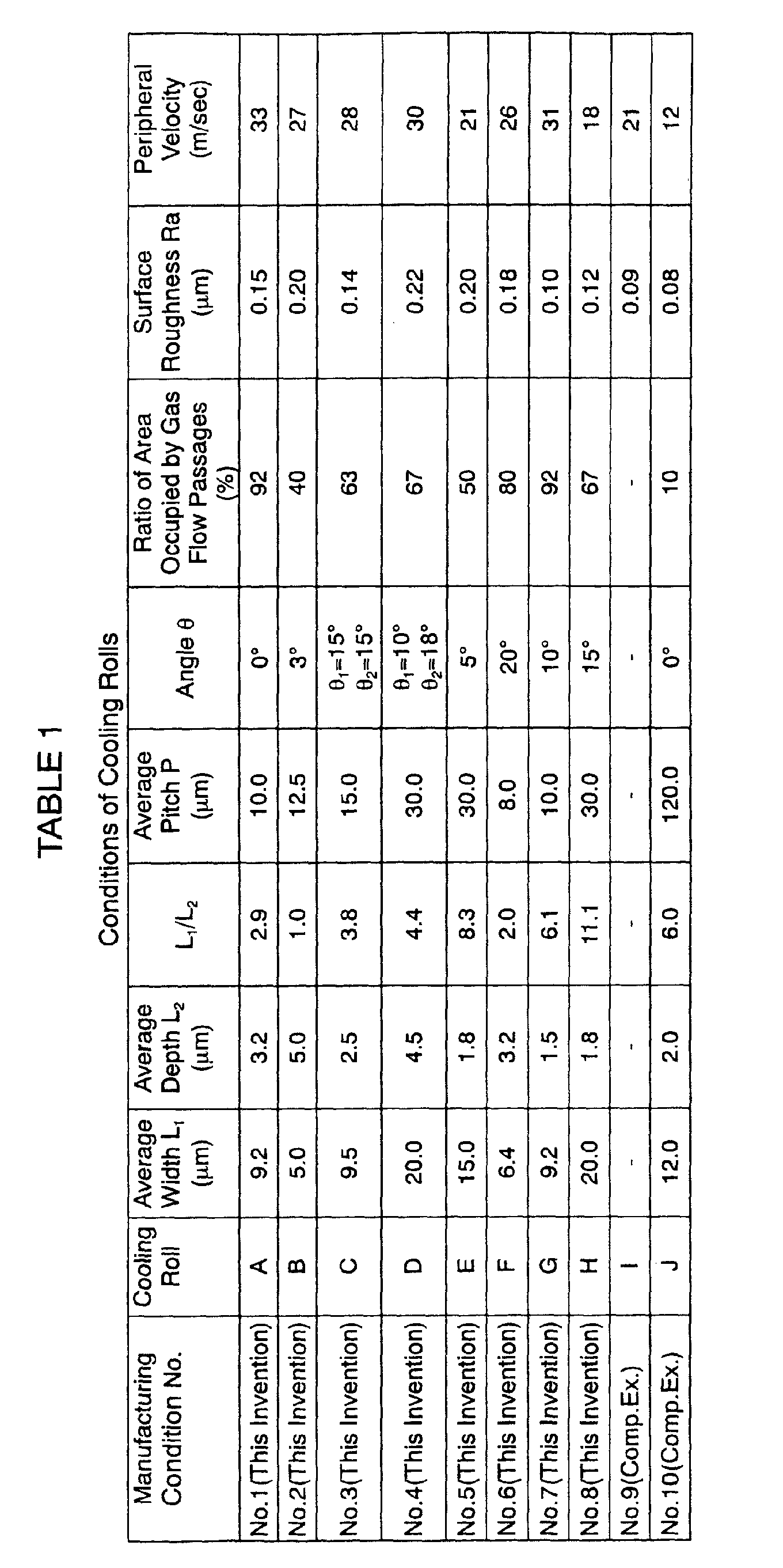


Claims (34)
- A method of manufacturing magnetic powder in which the magnetic powder is manufactured by milling a ribbon-shaped magnetic material which has been obtained by colliding a molten alloy of a magnetic material to a circumferential surface of a rotating cooling roll so as to cool and then solidify it,
wherein the method is characterized in that the cooling roll is formed with gas flow passages as gas expelling means for expelling gas entered between the circumferential surface and a puddle of the molten alloy in the circumferential surface thereof, and, when the average pitch of these gas flow passages is defined as Pµm and the average particle size of the magnetic powder is defined as Dµm, the relationship represented by the formula P < D is satisfied. - The manufacturing method as claimed in claim 1, wherein the average particle size of the magnetic powder lies in the range of 5 to 300µm.
- The manufacturing method as claimed in claim 1, wherein the average pitch P of the gas flow passages lies in the range of 0.5µm or more and less than 100µm.
- The manufacturing method as claimed in claim 1, wherein the average width of the gas flow passages lies in the range of 0.5 to 90µm.
- The manufacturing method as claimed in claim 1, wherein the average depth of the gas flow passages lies in the range of 0.5 to 20µm.
- The manufacturing method as claimed in claim 1, wherein when the average width of the gas flow passages is defined as L1 and the average depth of the gas flow passages is defined as L2, the relationship represented by the formula of 0.5 ≤ L1/L2 ≤ 15 is satisfied.
- The manufacturing method as claimed in claim 1, wherein the cooling roll includes a roll base and an outer surface layer provided on an outer peripheral portion of the roll base, and said gas flow passages are provided in the outer surface layer.
- The manufacturing method as claimed in claim 7, wherein the outer surface layer of the cooling roll is formed of a material having heat conductivity lower than the heat conductivity of the structural material of the roll base at or around a room temperature.
- The manufacturing method as claimed in claim 7, wherein the heat conductivity of the outer surface layer of the cooling roll at or around a room temperature is equal to or less than 80W· m-1· K-1.
- The manufacturing method as claimed in claim 7, wherein the outer surface layer of the cooling roll is formed of a ceramics.
- The manufacturing method as claimed in claim 7, wherein the thickness of the outer surface layer of the cooling roll is 0.5 to 50µm.
- The manufacturing method as claimed in claim 7, wherein the outer surface layer of the cooling roll is manufactured without experience of machining process.
- The manufacturing method as claimed in claim 1, wherein the angle defined by the longitudinal direction of the gas flow passages and the rotational direction of the cooling roll is equal to or less than 30 degrees.
- The manufacturing method as claimed in claim 1, wherein the gas flow passages are formed spirally with respect to the rotation axis of the cooling roll.
- The manufacturing method as claimed in claim 1, wherein each gas flow passage has openings located at the peripheral edges of the circumferential surface.
- The manufacturing method as claimed in claim 1, wherein the ratio of the projected area of the gas flow passages with respect to the projected area of the circumferential surface is in the range of 10 - 99.5%.
- The manufacturing method as claimed in claim 1, wherein said ribbon-shaped magnetic material has a roll contact surface which has been in contact with the cooling roll, in which the shape of the circumferential surface of the cooling roll is transferred to at least a part of the roll contact surface of the ribbon-shaped magnetic material.
- Magnetic powder which is manufactured according to the manufacturing method as defined in any one of claims 1 to 17.
- The magnetic powder as claimed in claim 18, wherein the magnetic powder contains particles each of which is formed with a plurality of recesses or ridges in at least a part of its surface.
- The magnetic powder as claimed in claim 19, wherein when the average diameter of the particles of the magnetic powder is defined as Dµm, the average length of the ridges or recesses is equal to or greater than D/40µm.
- The magnetic powder as claimed in claim 19, wherein the average height of the ridges or the average depth of the recesses is in the range of 0.1 to 10µm.
- The magnetic powder as claimed in claim 19, wherein the ridges or recesses are formed in parallel with each other, in which the average pitch of the adjacent ridges or recesses is in the range of 0.5 to 100µm.
- The magnetic powder as claimed in claim 19, wherein the ratio of an area of a portion of the particle where the ridges or recesses are formed with respect to the total surface area of the particle is equal to or greater than 15%.
- The magnetic powder as claimed in claim 18, wherein the average particle size of the magnetic powder is in the range of 5 to 300µm.
- The magnetic powder as claimed in claim 18, wherein the magnetic powder is subjected to at least one heat treatment during or after the manufacturing process thereof.
- The magnetic powder as claimed in claim 18, wherein the magnetic powder has a composite structure composed of a hard magnetic phase and a soft magnetic phase.
- The magnetic powder as claimed in claim 26, wherein the average crystal grain size of each of the hard magnetic phase and the soft magnetic phase is in the range of 1 - 100nm.
- A bonded magnet which is manufactured by binding the magnetic powder defined in any one of claims 18 to 27 with a binding resin.
- A bonded magnet which is manufactured by binding the magnetic powder defined in any one of claims 19 to 27 with a binding resin, wherein the binding resin enters between the ridges or into the recesses.
- The bonded magnet as claimed in claim 28, wherein the bonded magnet is manufactured by a warm molding.
- The bonded magnet as claimed in claim 28, wherein the intrinsic coercive force (HCJ) of the bonded magnet at a room temperature lies within the range of 320 - 1200 kA/m.
- The bonded magnet as claimed in claim 28, wherein the maximum magnetic energy product (BH)max of the bonded magnet is equal to or greater than 40kJ/m3.
- The bonded magnet as claimed in claim 28, wherein the content of the magnetic powered contained in the bonded magnet is in the range of 75 to 99.5wt%.
- The bonded magnet as claimed in claim 28, wherein the mechanical strength of the bonded magnet which is measured by the shear strength by punching-out test is equal to or greater than 50MPa.
Applications Claiming Priority (2)
| Application Number | Priority Date | Filing Date | Title |
|---|---|---|---|
| JP2000232488 | 2000-07-31 | ||
| JP2000232488A JP3587140B2 (en) | 2000-07-31 | 2000-07-31 | Method for producing magnet powder, magnet powder and bonded magnet |
Publications (3)
| Publication Number | Publication Date |
|---|---|
| EP1178503A2 true EP1178503A2 (en) | 2002-02-06 |
| EP1178503A3 EP1178503A3 (en) | 2002-11-06 |
| EP1178503B1 EP1178503B1 (en) | 2007-03-21 |
Family
ID=18725168
Family Applications (1)
| Application Number | Title | Priority Date | Filing Date |
|---|---|---|---|
| EP01118452A Expired - Lifetime EP1178503B1 (en) | 2000-07-31 | 2001-07-31 | Method of manufacturing magnetic powder, magnetic powder and bonded magnets |
Country Status (7)
| Country | Link |
|---|---|
| US (2) | US6554913B2 (en) |
| EP (1) | EP1178503B1 (en) |
| JP (1) | JP3587140B2 (en) |
| KR (1) | KR100427151B1 (en) |
| CN (1) | CN100467171C (en) |
| DE (1) | DE60127353T2 (en) |
| TW (1) | TW563138B (en) |
Families Citing this family (3)
| Publication number | Priority date | Publication date | Assignee | Title |
|---|---|---|---|---|
| WO2005095024A1 (en) | 2004-03-31 | 2005-10-13 | Santoku Corporation | Process for producing alloy slab for rare-earth sintered magnet, alloy slab for rare-earth sintered magnet and rare-earth sintered magnet |
| CN100400199C (en) * | 2004-03-31 | 2008-07-09 | 株式会社三德 | Alloy cast sheet for rare earth sintered magnet, manufacturing method thereof, and rare earth sintered magnet |
| US9224526B1 (en) * | 2010-05-24 | 2015-12-29 | Utron Kinetics, LLC | Magnet construction by combustion driven high compaction |
Family Cites Families (27)
| Publication number | Priority date | Publication date | Assignee | Title |
|---|---|---|---|---|
| US4212343A (en) * | 1979-03-16 | 1980-07-15 | Allied Chemical Corporation | Continuous casting method and apparatus for structurally defined metallic strips |
| US4408653A (en) * | 1981-11-09 | 1983-10-11 | Allied Corporation | Method for making serrated metal ribbon |
| US4705095A (en) * | 1986-01-09 | 1987-11-10 | Ribbon Technology Corporation | Textured substrate and method for the direct, continuous casting of metal sheet exhibiting improved uniformity |
| DE3606804A1 (en) | 1986-03-01 | 1987-09-10 | Thyssen Huette Ag | METALLIC SEMI-FINISHED PRODUCT AND METHOD FOR THE PRODUCTION AND USE THEREOF |
| JPS6442501A (en) | 1987-08-07 | 1989-02-14 | Matsushita Electric Works Ltd | Production of permanent magnet |
| US4819712A (en) * | 1987-09-28 | 1989-04-11 | Battelle Development Corporation | Method and apparatus for continuous casting of molten metal |
| US4934443A (en) * | 1988-02-16 | 1990-06-19 | Reynolds Metals Company | Method of and apparatus for direct casting of metal strip |
| JPH02165849A (en) | 1988-09-27 | 1990-06-26 | Kawasaki Steel Corp | Cooling roll for reducing twin roll type rapidly cooled strip |
| US4903751A (en) * | 1988-11-04 | 1990-02-27 | Ribbon Technology Corporation | Two wheel melt overflow process and apparatus |
| FI90400C (en) * | 1990-05-23 | 1994-02-10 | Bretec Oy | Hydraulic hammer |
| JP3502107B2 (en) | 1991-08-29 | 2004-03-02 | Tdk株式会社 | Manufacturing method of permanent magnet material |
| JP3248942B2 (en) * | 1992-03-24 | 2002-01-21 | ティーディーケイ株式会社 | Cooling roll, method for manufacturing permanent magnet material, permanent magnet material, and permanent magnet material powder |
| JPH05337611A (en) | 1992-06-04 | 1993-12-21 | Seiko Epson Corp | Production of alloy for rare earth metal bonded magnet |
| JPH08176648A (en) | 1994-12-28 | 1996-07-09 | Nippon Steel Corp | Hearth roll for heat treatment furnace |
| JPH08215801A (en) | 1995-02-17 | 1996-08-27 | Nippon Steel Corp | Quenched metal ribbon and its manufacturing equipment |
| JPH09271909A (en) * | 1996-04-05 | 1997-10-21 | Nippon Steel Corp | Cooling substrate for manufacturing quenched metal ribbon |
| JPH1041114A (en) | 1996-07-19 | 1998-02-13 | Tokin Corp | Method for producing powder for polymer composite type rare earth magnet |
| JP3771710B2 (en) | 1997-03-14 | 2006-04-26 | 住友金属工業株式会社 | Raw material alloy for rare earth magnet and method for producing the same |
| JPH1154306A (en) | 1997-07-31 | 1999-02-26 | Seiko Epson Corp | Magnet alloy ribbon and resin-bonded bonded magnet |
| JPH11309549A (en) * | 1998-04-24 | 1999-11-09 | Seiko Epson Corp | Manufacturing method of magnet material, magnet material and bonded magnet |
| JP2000077219A (en) * | 1998-08-27 | 2000-03-14 | Seiko Epson Corp | Manufacturing method of magnet material, magnet material and bonded magnet |
| JP4374633B2 (en) | 1998-12-15 | 2009-12-02 | 日立金属株式会社 | Method for producing raw material alloy for nanocomposite magnet, and method for producing nanocomposite magnet powder and magnet |
| JP2000345313A (en) | 1999-06-08 | 2000-12-12 | Nippon Steel Hardfacing Co Ltd | Roll manufacturing method for continuous casting with improved heat resistance, corrosion resistance and wear resistance of the roll body substrate surface subjected to repeated thermal shock and sliding wear |
| JP3611107B2 (en) | 2000-04-12 | 2005-01-19 | セイコーエプソン株式会社 | Cooling roll |
| JP3728396B2 (en) | 2000-04-12 | 2005-12-21 | セイコーエプソン株式会社 | Manufacturing method of magnet material |
| JP3277933B2 (en) * | 2000-04-24 | 2002-04-22 | セイコーエプソン株式会社 | Magnet powder, method for producing bonded magnet, and bonded magnet |
| JP2002035899A (en) | 2000-07-31 | 2002-02-05 | Seiko Epson Corp | Cooling roll, ribbon-shaped magnet material, magnet powder and bonded magnet |
-
2000
- 2000-07-31 JP JP2000232488A patent/JP3587140B2/en not_active Expired - Fee Related
-
2001
- 2001-07-31 EP EP01118452A patent/EP1178503B1/en not_active Expired - Lifetime
- 2001-07-31 KR KR10-2001-0046349A patent/KR100427151B1/en not_active Expired - Fee Related
- 2001-07-31 TW TW090118631A patent/TW563138B/en active
- 2001-07-31 DE DE60127353T patent/DE60127353T2/en not_active Expired - Lifetime
- 2001-07-31 CN CNB011407131A patent/CN100467171C/en not_active Expired - Fee Related
- 2001-07-31 US US09/919,242 patent/US6554913B2/en not_active Expired - Fee Related
-
2003
- 2003-02-25 US US10/373,973 patent/US6872326B2/en not_active Expired - Fee Related
Also Published As
| Publication number | Publication date |
|---|---|
| DE60127353D1 (en) | 2007-05-03 |
| US6554913B2 (en) | 2003-04-29 |
| US6872326B2 (en) | 2005-03-29 |
| TW563138B (en) | 2003-11-21 |
| EP1178503A3 (en) | 2002-11-06 |
| EP1178503B1 (en) | 2007-03-21 |
| CN100467171C (en) | 2009-03-11 |
| KR20020011125A (en) | 2002-02-07 |
| KR100427151B1 (en) | 2004-04-14 |
| JP2002050507A (en) | 2002-02-15 |
| US20020066498A1 (en) | 2002-06-06 |
| JP3587140B2 (en) | 2004-11-10 |
| CN1342537A (en) | 2002-04-03 |
| DE60127353T2 (en) | 2007-11-29 |
| US20030213532A1 (en) | 2003-11-20 |
Similar Documents
| Publication | Publication Date | Title |
|---|---|---|
| EP1160807B1 (en) | Cooling roll, ribbon-shaped magnetic materials and method for manufacturing thereof | |
| EP1146525B1 (en) | Cooling roll | |
| EP1160803A2 (en) | Magnetic powder, manufacturing method of magnetic powder and bonded magnets | |
| EP1162634A1 (en) | Magnetic powder, manufacturing method of magnetic powder and bonded magnets | |
| US6830633B2 (en) | Magnetic material manufacturing method, ribbon-shaped magnetic materials, powdered magnetic materials and bonded magnets | |
| EP1146524B1 (en) | Method of manufacturing magnetic materials, powdered magnetic materials and a bonded magnet | |
| EP1168380B1 (en) | Thin strip magnet material, magnet powder and rare earth bond magnet | |
| EP1178503B1 (en) | Method of manufacturing magnetic powder, magnetic powder and bonded magnets | |
| JP3988644B2 (en) | Magnet powder and bonded magnet | |
| JP3988643B2 (en) | Magnet powder and bonded magnet | |
| JP2003077748A (en) | Cooling roll, ribbon-shaped magnet material, magnet powder and bonded magnet | |
| JP2000286114A (en) | Thin strip magnet material, magnet powder and rare earth bonded magnet | |
| JP2001274009A (en) | Magnet powder and isotropic bonded magnet | |
| JP2002035899A (en) | Cooling roll, ribbon-shaped magnet material, magnet powder and bonded magnet |
Legal Events
| Date | Code | Title | Description |
|---|---|---|---|
| PUAI | Public reference made under article 153(3) epc to a published international application that has entered the european phase |
Free format text: ORIGINAL CODE: 0009012 |
|
| AK | Designated contracting states |
Kind code of ref document: A2 Designated state(s): AT BE CH CY DE DK ES FI FR GB GR IE IT LI LU MC NL PT SE TR |
|
| AX | Request for extension of the european patent |
Free format text: AL;LT;LV;MK;RO;SI |
|
| PUAL | Search report despatched |
Free format text: ORIGINAL CODE: 0009013 |
|
| AK | Designated contracting states |
Kind code of ref document: A3 Designated state(s): AT BE CH CY DE DK ES FI FR GB GR IE IT LI LU MC NL PT SE TR |
|
| AX | Request for extension of the european patent |
Free format text: AL;LT;LV;MK;RO;SI |
|
| RIC1 | Information provided on ipc code assigned before grant |
Free format text: 7H 01F 41/02 A, 7H 01F 1/057 B, 7H 01F 1/059 B, 7H 01F 1/055 B |
|
| 17P | Request for examination filed |
Effective date: 20021121 |
|
| AKX | Designation fees paid |
Designated state(s): DE FR GB |
|
| 17Q | First examination report despatched |
Effective date: 20040517 |
|
| GRAP | Despatch of communication of intention to grant a patent |
Free format text: ORIGINAL CODE: EPIDOSNIGR1 |
|
| GRAS | Grant fee paid |
Free format text: ORIGINAL CODE: EPIDOSNIGR3 |
|
| GRAA | (expected) grant |
Free format text: ORIGINAL CODE: 0009210 |
|
| AK | Designated contracting states |
Kind code of ref document: B1 Designated state(s): DE FR GB |
|
| REG | Reference to a national code |
Ref country code: GB Ref legal event code: FG4D |
|
| REF | Corresponds to: |
Ref document number: 60127353 Country of ref document: DE Date of ref document: 20070503 Kind code of ref document: P |
|
| ET | Fr: translation filed | ||
| PLBE | No opposition filed within time limit |
Free format text: ORIGINAL CODE: 0009261 |
|
| STAA | Information on the status of an ep patent application or granted ep patent |
Free format text: STATUS: NO OPPOSITION FILED WITHIN TIME LIMIT |
|
| 26N | No opposition filed |
Effective date: 20071227 |
|
| PGFP | Annual fee paid to national office [announced via postgrant information from national office to epo] |
Ref country code: FR Payment date: 20110727 Year of fee payment: 11 |
|
| PGFP | Annual fee paid to national office [announced via postgrant information from national office to epo] |
Ref country code: GB Payment date: 20110727 Year of fee payment: 11 Ref country code: DE Payment date: 20110727 Year of fee payment: 11 |
|
| GBPC | Gb: european patent ceased through non-payment of renewal fee |
Effective date: 20120731 |
|
| REG | Reference to a national code |
Ref country code: FR Ref legal event code: ST Effective date: 20130329 |
|
| PG25 | Lapsed in a contracting state [announced via postgrant information from national office to epo] |
Ref country code: FR Free format text: LAPSE BECAUSE OF NON-PAYMENT OF DUE FEES Effective date: 20120731 Ref country code: DE Free format text: LAPSE BECAUSE OF NON-PAYMENT OF DUE FEES Effective date: 20130201 Ref country code: GB Free format text: LAPSE BECAUSE OF NON-PAYMENT OF DUE FEES Effective date: 20120731 |
|
| REG | Reference to a national code |
Ref country code: DE Ref legal event code: R119 Ref document number: 60127353 Country of ref document: DE Effective date: 20130201 |