EP1178201B1 - Brennstoffabschaltung im Schubbetrieb - Google Patents
Brennstoffabschaltung im Schubbetrieb Download PDFInfo
- Publication number
- EP1178201B1 EP1178201B1 EP01306078A EP01306078A EP1178201B1 EP 1178201 B1 EP1178201 B1 EP 1178201B1 EP 01306078 A EP01306078 A EP 01306078A EP 01306078 A EP01306078 A EP 01306078A EP 1178201 B1 EP1178201 B1 EP 1178201B1
- Authority
- EP
- European Patent Office
- Prior art keywords
- combustion chamber
- engine
- internal combustion
- vehicle
- poppet valve
- Prior art date
- Legal status (The legal status is an assumption and is not a legal conclusion. Google has not performed a legal analysis and makes no representation as to the accuracy of the status listed.)
- Expired - Lifetime
Links
Images


Classifications
-
- F—MECHANICAL ENGINEERING; LIGHTING; HEATING; WEAPONS; BLASTING
- F02—COMBUSTION ENGINES; HOT-GAS OR COMBUSTION-PRODUCT ENGINE PLANTS
- F02D—CONTROLLING COMBUSTION ENGINES
- F02D41/00—Electrical control of supply of combustible mixture or its constituents
- F02D41/008—Controlling each cylinder individually
- F02D41/0087—Selective cylinder activation, i.e. partial cylinder operation
-
- F—MECHANICAL ENGINEERING; LIGHTING; HEATING; WEAPONS; BLASTING
- F02—COMBUSTION ENGINES; HOT-GAS OR COMBUSTION-PRODUCT ENGINE PLANTS
- F02D—CONTROLLING COMBUSTION ENGINES
- F02D13/00—Controlling the engine output power by varying inlet or exhaust valve operating characteristics, e.g. timing
- F02D13/02—Controlling the engine output power by varying inlet or exhaust valve operating characteristics, e.g. timing during engine operation
- F02D13/06—Cutting-out cylinders
-
- F—MECHANICAL ENGINEERING; LIGHTING; HEATING; WEAPONS; BLASTING
- F02—COMBUSTION ENGINES; HOT-GAS OR COMBUSTION-PRODUCT ENGINE PLANTS
- F02D—CONTROLLING COMBUSTION ENGINES
- F02D41/00—Electrical control of supply of combustible mixture or its constituents
- F02D41/02—Circuit arrangements for generating control signals
- F02D41/04—Introducing corrections for particular operating conditions
- F02D41/12—Introducing corrections for particular operating conditions for deceleration
- F02D41/123—Introducing corrections for particular operating conditions for deceleration the fuel injection being cut-off
-
- F—MECHANICAL ENGINEERING; LIGHTING; HEATING; WEAPONS; BLASTING
- F02—COMBUSTION ENGINES; HOT-GAS OR COMBUSTION-PRODUCT ENGINE PLANTS
- F02D—CONTROLLING COMBUSTION ENGINES
- F02D41/00—Electrical control of supply of combustible mixture or its constituents
- F02D41/0002—Controlling intake air
- F02D2041/001—Controlling intake air for engines with variable valve actuation
- F02D2041/0012—Controlling intake air for engines with variable valve actuation with selective deactivation of cylinders
-
- Y—GENERAL TAGGING OF NEW TECHNOLOGICAL DEVELOPMENTS; GENERAL TAGGING OF CROSS-SECTIONAL TECHNOLOGIES SPANNING OVER SEVERAL SECTIONS OF THE IPC; TECHNICAL SUBJECTS COVERED BY FORMER USPC CROSS-REFERENCE ART COLLECTIONS [XRACs] AND DIGESTS
- Y02—TECHNOLOGIES OR APPLICATIONS FOR MITIGATION OR ADAPTATION AGAINST CLIMATE CHANGE
- Y02T—CLIMATE CHANGE MITIGATION TECHNOLOGIES RELATED TO TRANSPORTATION
- Y02T10/00—Road transport of goods or passengers
- Y02T10/10—Internal combustion engine [ICE] based vehicles
- Y02T10/12—Improving ICE efficiencies
Definitions
- the field of the present invention is that of automotive engines, in particularly automotive engines having deceleration fuel shut off.
- Deceleration fuel shut off can lead up to four percent fuel savings on the combined Federal Test Procedure cycle. Even greater fuel savings are possible with drive cycles which include more deceleration time.
- One of the problems in implementing DFSO is transient fuel behaviour in the intake system. Transient fuel behaviour can be alleviated with direct in-cylinder fuel injection or more advanced port fuel injection systems with less wall wetting.
- a second problem in implementing DFSO is the more intense vehicle deceleration due to increased braking by the engine. The problem of increased braking by the engine can be resolved by increased driver acclimation and by acknowledgement of the benefit of less stress and wear upon the vehicle braking system.
- the third issue and the hardest technical challenge to overcome is the issue of excessive air being pumped to the engine exhaust system. Excessive air causes cooling and oxygen loading of the exhaust system catalyst under normal DFSO conditions.
- an internal combustion engine and a method of operation thereof which allows DFSO. It is also desirable to provide an arrangement of an internal combustion engine and a method of operation thereof which allows DFSO without causing cooling or excessive oxygen loading of the vehicle catalyst in order to avoid degrading the NOx conversion efficiency of the catalyst upon subsequent engine operation. It is further desirable to provide an internal combustion engine and a method of operation thereof with the above-noted features which can also be utilised to provide engine braking when high levels of vehicle deceleration are desired.
- the intake event of the cylindrical combustion chamber intake poppet valves is phased to be symmetric about the top dead centre (phase advanced) or preferably the bottom dead centre (phase retarded) position. Equal amounts of airflow are pulled into the combustion chamber via the intake valve opening during the intake stroke and expelled through the inlet valve opening from the combustion chamber during the first part of the compression stroke minimising pumping work.
- the exhaust poppet valve is deactivated. Accordingly, during this period of deceleration, the fuel can be shut off from the vehicle. If additional braking is required, the intake cam can be advanced to standard timing. The advancement of the intake cam to standard timing increases pumping work and engine braking.
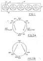
- Figure 1 is a schematic view of a single bank of deactivatable cylinder combustion chambers in a V-10 internal combustion engine built and operated according to the principles of the present invention wherein each cylinder has a single exhaust and dual intake poppet valves.
- Figure 2A is a schematic view illustrating opening and closing timing of the inlet poppet valves in the internal combustion engine with the deactivatable combustion chambers as shown in Figure 1 wherein the opening and closing of the intake poppet valves for a deactivated cylinder are retarded to be generally symmetric about a bottom dead centre position of an engine piston.
- Figure 2B is a schematic view illustrating opening and closing timing of the inlet poppet valves in the internal combustion engine with the deactivatable combustion chambers as shown in Figure 1, wherein the opening and closing of the intake poppet valves for a deactivated cylinder are advanced to be generally symmetric about a top dead centre position of an engine piston.
- Figure 3 is a pressure volume diagram illustrating work of a deactivated cylindrical combustion chamber which has a disabled exhaust poppet valve and a normal phase operating inlet poppet valve inlet.
- Figure 4 is a pressure volume diagram similar to that of Figure 3 illustrating the work of a deactivated cylinder in an internal combustion engine arrangement according to the present invention.
- Figures 5A through 5H are schematic views illustrating the operation of the inlet and outlet poppet valves during the deactivated stage of operation of a cylinder in the internal combustion engine arrangement according to the present invention.
- Figures 6 and 7 give an example of a poppet valve disablement which can be utilised on the exhaust valve in an internal combustion engine arrangement of the present invention.
- Figure 8 is a schematic view of the operation of an engine controller internal combustion engine of the present invention.
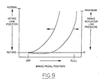
- Figure 9 is a chart illustrating a function relationship of brake system pressure and cam phase operation when utilising the present inventive internal combustion engine to brake a vehicle.
- a four-cycle internal combustion engine arrangement 8 built and operated according to the present invention has a bank of cylindrical combustion chambers 12 which are presented in a V-formation.
- Each combustion chamber 12 has a reciprocating piston 15 slidably mounted therein.
- the piston 15 is pivotally connected with a piston rod 19 which is in turn pivotally connected on an engine crankshaft (not shown).
- Each combustion chamber 12 has a single exhaust poppet valve 14 and two intake poppet valves 16.
- the exhaust poppet valves 14 are driven by a phase variable camshaft 17 ( Figures 6 and 7).
- the camshaft 17 has connected thereto a series of cams 18 (only one shown).
- Each of the cams 18 contacts a rocker arm 20.
- the rocker arm 20 (associated with an exhaust valve 14 of one of the deactivatable combustion chambers 12), on one end pivots on a fulcrum 23.
- the fulcrum 23 is provided by the end of a hydraulic valve lifter 22.
- An opposite end 24 of the rocker arm 20 pushes a top end of the exhaust valve 14 downward to open the exhaust valve 14 when the cam 18 is at the position shown.
- an engine controller under the appropriate desired vehicle load conditions will signal for a deactivation of the cylinders 12.
- valve lifter 22 will be signalled to move the fulcrum 23 down to disable the exhaust valve 14.
- intake valves 16 are operated by a phase retardable cam.
- the cam can be on the same camshaft 17 which drives the exhaust valve 14.
- the camshaft 17 and associated cams are retarded by a cam phaser such as a helical spline cam phaser found on the Ford Motor Company 2.0L 1998 Escort engine.
- the retardation will be between 60 and 70 degrees and is preferably 65 degrees and is symmetric about the bottom dead centre position 45 of the piston ( Figure 2).
- the exhaust valve 14 has been disabled to its closed position.
- the inlet stroke of the piston 15 is beginning. In normal operation the inlet valve 16 opens during the very last stages of the exhaust stroke of the piston 15.
- the piston 15 has moved downward.
- the intake valve 16 is still closed during the initial inlet stroke.
- the initial valve opening (IVO) of valve 16 is shown in Figure 5C and, in Figure 2A at point 41 is approximately 60 to 70 degrees and preferably 65 degrees from the normal initial valve opening point 43 which is 10 to 15 degrees from the top dead centre position of the piston 15. Referring to Figure 4, the IVO will take place at approximately 55 crank angle degrees after top dead centre at point 41.
- the intake valve 16 is still open.
- the intake valve 16 remains open at the position shown in Figure 5E and only closes at the phantom position shown in Figure 5E approximately 55 crank angle degrees before top dead centre.
- Figure 2B illustrates an alternate embodiment of the present invention.
- the engine arrangement shown in Figure 2B is identical to that described with limited exception.
- the IVO 41A and the IVC 47A are symmetrical about the top dead centre position of the piston.
- the exhaust poppet valve 14 is disabled.
- the engine arrangement and method of Figure 2B requires a greater clearance between the top dead centre position of the piston 15 and the top of the combustion chamber 12 since the inlet valve 16 is open when the piston 15 is at the top dead centre position. Accordingly, for most applications the embodiment of the invention shown in Figure 2A will be found to be preferable.
- the engine controller 70 has several inputs.
- the engine controller 70 is cognisant of the condition of the vehicle brake system by monitoring brake pedal 72 position, master cylinder 74 pressure or other brake system operational parameters from the braking system controller 76.
- the engine controller 70 is also connected with the engine fuel system 78, the engine block 80, the intake cam phaser 82, and with a positional input from the accelerator pedal 83. From the aforementioned inputs and other inputs, the engine controller will be cognisant of a desired deceleration of the vehicle the engine is powering 84. Under appropriate conditions, when a desired deceleration event occurs, the engine controller 70 will signal the cam phaser to phase the intake poppet valve cam operation to be symmetric, preferably about the bottom centre position.
- the exhaust poppet valve 14 will be signalled to the closed position.
- the engine controller 70 will signal the engine fuel system 78 to go to a deceleration fuel shut-off mode of operation.
- the engine controller 70 first will signal the cam phaser 82 to return the intake valve cam operation to its normal operation to allow the engine 80 to brake the vehicle 84.
- the braking system controller 76 allows the brake line pressure (in part determined by the brake pressure modulator 75) to the wheel actuators 77 to increase. This mode of operation is especially beneficial when the present invention is used in large vehicles and/or trucks.
- Figure 9 illustrates a relationship between brake pedal position, brake actuator line pressure, and desired intake cam position for the embodiment of the present invention having cam retard and valve operation symmetric about the bottom dead centre position.
Landscapes
- Engineering & Computer Science (AREA)
- Chemical & Material Sciences (AREA)
- Combustion & Propulsion (AREA)
- Mechanical Engineering (AREA)
- General Engineering & Computer Science (AREA)
- Output Control And Ontrol Of Special Type Engine (AREA)
- Valve Device For Special Equipments (AREA)
Claims (15)
- Anordnung einer Viertakt-Brennkraftmaschine für ein Kraftfahrzeug, folgendes aufweisend:eine Motorsteuerung, welcher eine Soll-Verzögerungsbedingung für ein von besagtem Motor angetriebenes Fahrzeug bekannt ist; undwenigstens einen ersten Brennraum mit einem darin eingesetzten hin- und hergehenden Kolben, wobei besagter Kolben eine obere Totpunkt- und eine untere Totpunktlage hat welcher besagter erster Brennraum ein von einem Nocken betätigtes Auslaß-Tellerventil aufweist, das selektiv in einer Schließstellung stillgelegt werden kann, so daß besagter erster Brennraum in Reaktion auf ein von besagter Motorsteuerung gesendetes Signal deaktiviert werden kann, wobei besagter erster Brennraum außerdem ein über einen phasenverstellbaren Nocken betätigtes Einlaß-Tellerventil beinhaltet, das auf ein von besagter Motorsteuerung gesendetes Signal so anspricht, daß der Öffnungs- und Schließbetrieb des besagten Tellerventils selektiv so eingestellt werden kann, daß er während der besagten Deaktivierung des besagten ersten Brennraumes während besagter Fahrzeugverzögerung allgemein symmetrisch um eine der beiden besagten Totpunktlagen liegt, und so auf ein von besagter Motorsteuerung gesendetes Signal anspricht, daß der Öffnungs-und Schließbetrieb des besagten Einlaß-Tellerventils in eine normale Betriebsphase zurückgestellt wird, um eine erhöhte Motorbremswirkung zu erzeugen.
- Anordnung einer Brennkraftmaschine nach Anspruch 1, worin besagte selektive Einstellung der besagten Öffnung des besagten Einlaß-Tellerventils während der besagten Deaktivierung des besagten ersten Brennraumes in einem Abstand von etwa 60 bis 70 Grad von besagter oberer Totpunktlage des besagten Kolbens liegt.
- Anordnung einer Brennkraftmaschine nach Anspruch 2, worin besagte selektive Einstellung des besagten Einlaß-Tellerventils des ersten Brennraumes in einem Abstand von etwa 65 Grad von besagter oberer Totpunktlage des besagten Kolbens liegt.
- Anordnung einer Brennkraftmaschine nach Anspruch 1, worin besagter Öffnungs- und Schließbetrieb des besagten Einlaß-Tellerventils für besagten ersten Zylinder bei deaktiviertem besagtem erstem Brennraum allgemein symmetrisch um besagte untere Totpunktlage des besagten hin- und hergehenden Kolbens in besagtem erstem Brennraum liegt.
- Anordnung einer Brennkraftmaschine nach Anspruch 1, worin besagter erster Brennraum ein Auslaß-Tellerventil und mehrere Einlaß-Tellerventile hat, und besagte Einlaß-Tellerventile von einer gemeinsamen Nockenwelle betätigt werden.
- Anordnung einer Brennkraftmaschine nach Anspruch 5, worin besagte gemeinsame Nockenwelle Nocken für besagte Einlaß- und besagte Auslaßventile für besagten ersten Brennraum treibt.
- Anordnung einer Brennkraftmaschine nach Anspruch 1, worin besagter Motorsteuerung ein variabler Soll-Verzögerungswert des besagten Fahrzeuges bekannt ist, und worin besagte Motorsteuerung die Betriebsphase des besagten Nockens gegenüber einer Normalbetriebsphase so verstellt, daß besagter Motor besagtes Fahrzeug mit einem vorgegebenen Soll-Verzögerungspegel des besagten Fahrzeuges abbremst.
- Anordnung einer Brennkraftmaschine nach Anspruch 7, worin besagte Motorsteuerung beim Bestimmen der besagten Soll-Verzögerung des besagten Fahrzeuges über den Betrieb der besagten Fahrzeugbremsanlage informiert ist.
- Verfahren zum Betreiben einer Viertakt-Brennkraftmaschine mit wenigstens einem Brennraum mit einem hin- und hergehenden Kolben, mit von Nocken betätigten Einlaß- und Auslaß-Tellerventilen, wobei besagter Kolben eine obere Totpunktlage und eine untere Totpunktlage hat, welches Verfahren die selektive Deaktivierung wenigstens eines der besagten Brennräume während eines Soll-Verzögerungsereignisses des besagten Fahrzeuges beinhaltet, und welches Verfahren folgendes beinhaltet:Deaktivieren des besagten von einem Nocken betätigten Auslaß-Tellerventils für besagten deaktivierten Brennraum: undVerstellen der Betriebsphase des besagten, die Öffnung und Schließung der besagten Einlaß-Tellerventile des deaktivierten Brennraumes steuernden Nockens derart, daß sie allgemein symmetrisch um eine der besagten Totpunktlagen des Kolbens liegt, so daß ein erster Soll-Verzögerungspegel geschaffen wird, und Zurückstellen des Öffnungs- und Schließbetriebes der besagten Einlaß-Tellerventile auf eine normale Betriebsphase zur Schaffung eines zweiten Soll-Verzögerungspegels.
- Verfahren zum Betreiben einer Brennkraftmaschine nach Anspruch 9, worin besagter Betrieb des besagten Einlaß-Tellerventils für den besagten deaktivierten Brennraum allgemein symmetrisch um besagte untere Totpunktlage des besagten Kolbens liegt.
- Verfahren zum Betreiben einer Brennkraftmaschine nach Anspruch 10, worin besagter Öffnungsbetrieb des besagten Einlaß-Tellerventils während der Deaktivierung des besagten Brennraumes in einem Abstand von etwa 60 bis 70 Grad von besagter oberer Totpunktlage des besagten Kolbens liegt.
- Verfahren zum Betreiben einer Brennkraftmaschine nach Anspruch 11, worin besagte Öffnung des besagten Einlaß-Tellerventils des deaktivierten Brennraumes in einem Abstand von etwa 65 Grad von besagter oberer Totpunktlage des besagten Kolbens liegt.
- Verfahren zum Betreiben einer Brennkraftmaschine nach Anspruch 9. worin mehrere besagte deaktivierbare Brennräume je ein Auslaß-Tellerventil und mehrere Einlaß-Tellerventile aufweisen, und worin besagte Einlaß- und Auslaß-Tellerventile von einer gemeinsamen Nockenwelle betätigt werden.
- Verfahren zum Betreiben einer Brennkraftmaschine nach Anspruch 9, worin die Betriebsphase des besagten, die Öffnung und Schließung des Einlaß-Tellerventils des besagten deaktivierten Brennraumes steuernden Nockens von einer allgemein symmetrisch um eine der besagten Totpunktlagen des besagten Kolbens liegenden Position in eine Normalbetriebsphasenposition verschoben wird, so daß besagter Motor dazu gebracht wird, besagtes Fahrzeug entsprechend einem Soll-Verzögerungspegel des besagten Fahrzeuges abzubremsen.
- Verfahren zum Betreiben einer Brennkraftmaschine nach Anspruch 14, worin besagte Rückstellung des Betriebes des besagten, die Öffnung und Schließung des besagten Einlaß-Tellerventils des besagten deaktivierten Zylinderbrennraumes steuernden Nockens in Reaktion auf eine Betriebsbedingung einer Bremsanlage des besagten Fahrzeuges bewirkt wird.
Applications Claiming Priority (2)
| Application Number | Priority Date | Filing Date | Title |
|---|---|---|---|
| US630472 | 2000-08-02 | ||
| US09/630,472 US6553962B1 (en) | 2000-08-02 | 2000-08-02 | Exhaust valve deactivation and intake valve phasing to enable deceleration fuel shut off and engine braking |
Publications (3)
| Publication Number | Publication Date |
|---|---|
| EP1178201A2 EP1178201A2 (de) | 2002-02-06 |
| EP1178201A3 EP1178201A3 (de) | 2003-12-17 |
| EP1178201B1 true EP1178201B1 (de) | 2006-03-01 |
Family
ID=24527312
Family Applications (1)
| Application Number | Title | Priority Date | Filing Date |
|---|---|---|---|
| EP01306078A Expired - Lifetime EP1178201B1 (de) | 2000-08-02 | 2001-07-13 | Brennstoffabschaltung im Schubbetrieb |
Country Status (3)
| Country | Link |
|---|---|
| US (1) | US6553962B1 (de) |
| EP (1) | EP1178201B1 (de) |
| DE (1) | DE60117483T2 (de) |
Cited By (1)
| Publication number | Priority date | Publication date | Assignee | Title |
|---|---|---|---|---|
| CN101258312B (zh) * | 2005-09-12 | 2011-02-16 | 沃尔沃拉斯特瓦格纳公司 | 用于操作内燃机的方法 |
Families Citing this family (26)
| Publication number | Priority date | Publication date | Assignee | Title |
|---|---|---|---|---|
| US6647947B2 (en) * | 2002-03-12 | 2003-11-18 | Ford Global Technologies, Llc | Strategy and control system for deactivation and reactivation of cylinders of a variable displacement engine |
| DE10211119A1 (de) * | 2002-03-14 | 2003-09-25 | Bosch Gmbh Robert | Steuerung eines Verbrennungsmotors im Schiebebetrieb |
| JP4685491B2 (ja) * | 2005-03-31 | 2011-05-18 | 日立オートモティブシステムズ株式会社 | ペダル装置 |
| US20080185194A1 (en) * | 2007-02-02 | 2008-08-07 | Ford Global Technologies, Llc | Hybrid Vehicle With Engine Power Cylinder Deactivation |
| US20090229553A1 (en) * | 2007-03-09 | 2009-09-17 | Bililies Theodore C | Engine System |
| FR2916806A1 (fr) | 2007-06-01 | 2008-12-05 | Renault Sas | Systeme de deconnexion des soupapes d'admission d'un moteur a combustion interne et fonctionnement de ce systeme |
| US8333063B2 (en) * | 2007-11-12 | 2012-12-18 | Ford Global Technologies, Llc | Hydrocarbon retaining system and method |
| CN101936388B (zh) * | 2009-06-29 | 2015-09-30 | 博格华纳公司 | 采用双轴线链条的dct变速器 |
| US8601892B2 (en) | 2010-01-12 | 2013-12-10 | Borgwarner Inc. | DCT transmission utilizing a two axis chain |
| CN102425517B (zh) * | 2011-10-28 | 2013-06-05 | 南京理工大学 | 一种气体燃料电控喷射装置 |
| US10408140B2 (en) | 2012-07-31 | 2019-09-10 | Tula Technology, Inc. | Engine control in fuel and/or cylinder cut off modes based on intake manifold pressure |
| US9328672B2 (en) * | 2012-07-31 | 2016-05-03 | Tula Technology, Inc. | Engine braking controller |
| US9790867B2 (en) | 2012-07-31 | 2017-10-17 | Tula Technology, Inc. | Deceleration cylinder cut-off |
| US10167799B2 (en) | 2012-07-31 | 2019-01-01 | Tula Technology, Inc. | Deceleration cylinder cut-off in a hybrid vehicle |
| WO2014026160A1 (en) | 2012-08-10 | 2014-02-13 | Tula Technology, Inc. | Split bank and multimode skip fire operation |
| EP3044447B1 (de) * | 2013-09-11 | 2020-12-09 | Scania CV AB | Verfahren zur steuerung eines verbrennungsmotors zur entschleunigung eines fahrzeugs |
| DE212016000178U1 (de) | 2015-09-25 | 2018-06-01 | Eaton Intelligent Power Limited | Steuerung zur Zylinderabschaltung |
| WO2017117289A1 (en) * | 2015-12-28 | 2017-07-06 | Eaton Corporation | Cylinder deactivation and engine braking for start or stop harmonics management |
| US11326533B2 (en) | 2016-01-19 | 2022-05-10 | Eaton Intelligent Power Limited | Cylinder deactivation and engine braking for thermal management |
| US10232841B2 (en) * | 2016-11-18 | 2019-03-19 | Ford Global Technologies, Llc | Methods and system for improving response of a hybrid vehicle |
| WO2018102542A1 (en) * | 2016-11-30 | 2018-06-07 | Cummins Inc. | Compression release valvetrain design |
| DE102017208788A1 (de) * | 2017-05-24 | 2018-11-29 | Robert Bosch Gmbh | Verfahren und Vorrichtung zum Betreiben eines fremdgezündeten Verbrennungsmotors |
| US10215116B2 (en) | 2017-06-01 | 2019-02-26 | Ford Global Technologies, Llc | System and method for operating an engine that includes a fuel vapor canister |
| US10648414B2 (en) * | 2018-05-22 | 2020-05-12 | Ford Global Technologies, Llc | Method and system for engine control |
| US11549455B2 (en) | 2019-04-08 | 2023-01-10 | Tula Technology, Inc. | Skip cylinder compression braking |
| US11085390B2 (en) | 2019-11-26 | 2021-08-10 | GM Global Technology Operations LLC | System and method for a motor vehicle with reduced fuel enrichment after a fuel cutoff event |
Family Cites Families (8)
| Publication number | Priority date | Publication date | Assignee | Title |
|---|---|---|---|---|
| US4033304A (en) | 1974-06-14 | 1977-07-05 | David Luria | Piston-type internal combustion engine |
| US4230076A (en) * | 1975-09-05 | 1980-10-28 | Eaton Corporation | Control for valve disablers |
| US4516542A (en) * | 1982-06-02 | 1985-05-14 | Nissan Motor Co., Ltd. | Valve operation changing system of internal combustion engine |
| US4592319A (en) * | 1985-08-09 | 1986-06-03 | The Jacobs Manufacturing Company | Engine retarding method and apparatus |
| US5377631A (en) | 1993-09-20 | 1995-01-03 | Ford Motor Company | Skip-cycle strategies for four cycle engine |
| US5642703A (en) | 1995-10-16 | 1997-07-01 | Ford Motor Company | Internal combustion engine with intake and exhaust camshaft phase shifting for cylinder deactivation |
| US5975052A (en) | 1998-01-26 | 1999-11-02 | Moyer; David F. | Fuel efficient valve control |
| US6161521A (en) * | 1998-11-04 | 2000-12-19 | Ford Global Technologies, Inc. | Internal combustion engine having deceleration fuel shut off and camshaft controlled charge trapping |
-
2000
- 2000-08-02 US US09/630,472 patent/US6553962B1/en not_active Expired - Lifetime
-
2001
- 2001-07-13 EP EP01306078A patent/EP1178201B1/de not_active Expired - Lifetime
- 2001-07-13 DE DE60117483T patent/DE60117483T2/de not_active Expired - Lifetime
Cited By (1)
| Publication number | Priority date | Publication date | Assignee | Title |
|---|---|---|---|---|
| CN101258312B (zh) * | 2005-09-12 | 2011-02-16 | 沃尔沃拉斯特瓦格纳公司 | 用于操作内燃机的方法 |
Also Published As
| Publication number | Publication date |
|---|---|
| EP1178201A2 (de) | 2002-02-06 |
| US6553962B1 (en) | 2003-04-29 |
| DE60117483T2 (de) | 2006-11-02 |
| DE60117483D1 (de) | 2006-04-27 |
| EP1178201A3 (de) | 2003-12-17 |
Similar Documents
| Publication | Publication Date | Title |
|---|---|---|
| EP1178201B1 (de) | Brennstoffabschaltung im Schubbetrieb | |
| US5408966A (en) | System and method for synchronously activating cylinders within a variable displacement engine | |
| EP0732489B1 (de) | Verstellung der Nockenwellenphase für Zylinderabschaltung | |
| US6752121B2 (en) | Cylinder deactivation system timing control synchronization | |
| US5992390A (en) | Fuel efficient hybrid internal combustion engine | |
| EP1442204B1 (de) | Verfahren und system zum verbessern der motorbremsung durch variable ventilbetätigung | |
| CN100385100C (zh) | 频率可调的可变压缩比发动机 | |
| US7278383B2 (en) | Internal combustion engine with variable compression ratio and valve characteristics | |
| US9657611B2 (en) | Variable displacement solenoid control | |
| US6237559B1 (en) | Cylinder deactivation via exhaust valve deactivation and intake cam retard | |
| JP2001527182A (ja) | 弁積極動力作動を伴うエンジン・ブレーキング | |
| WO2007018255A1 (en) | Internal combustion engine | |
| US7690350B2 (en) | Method and device for controlling an internal combustion engine with variable valve lift and motor vehicle equipped therewith | |
| US7406937B2 (en) | Method for operating an internal combustion engine | |
| CN111271149B (zh) | 内燃机系统 | |
| US7490001B2 (en) | Method for controlling the operation of a cylinder group for an internal combustion engine | |
| WO2009136900A2 (en) | Method for exhaust gas temperature control via engine braking in an internal combustion engine | |
| WO2015002777A1 (en) | Engine braking via advancing the exhaust valve | |
| US7152560B2 (en) | Engine valve performance controller | |
| US7668642B2 (en) | Control apparatus for internal combustion engine | |
| US11008952B2 (en) | Vacuum and compression release braking in spark-ignited engines | |
| US7603223B2 (en) | Apparatus for adjusting valve timing when starting internal combustion engine | |
| US20130220272A1 (en) | Engine control apparatus | |
| CN111448378B (zh) | 用于控制内燃发动机装置的方法 | |
| US12378910B1 (en) | Systems and methods for extra-stroke engine cycle operation |
Legal Events
| Date | Code | Title | Description |
|---|---|---|---|
| PUAI | Public reference made under article 153(3) epc to a published international application that has entered the european phase |
Free format text: ORIGINAL CODE: 0009012 |
|
| AK | Designated contracting states |
Kind code of ref document: A2 Designated state(s): AT BE CH CY DE DK ES FI FR GB GR IE IT LI LU MC NL PT SE TR |
|
| AX | Request for extension of the european patent |
Free format text: AL;LT;LV;MK;RO;SI |
|
| PUAL | Search report despatched |
Free format text: ORIGINAL CODE: 0009013 |
|
| AK | Designated contracting states |
Kind code of ref document: A3 Designated state(s): AT BE CH CY DE DK ES FI FR GB GR IE IT LI LU MC NL PT SE TR |
|
| AX | Request for extension of the european patent |
Extension state: AL LT LV MK RO SI |
|
| 17P | Request for examination filed |
Effective date: 20040428 |
|
| 17Q | First examination report despatched |
Effective date: 20040601 |
|
| AKX | Designation fees paid |
Designated state(s): DE GB SE |
|
| GRAP | Despatch of communication of intention to grant a patent |
Free format text: ORIGINAL CODE: EPIDOSNIGR1 |
|
| GRAS | Grant fee paid |
Free format text: ORIGINAL CODE: EPIDOSNIGR3 |
|
| GRAA | (expected) grant |
Free format text: ORIGINAL CODE: 0009210 |
|
| AK | Designated contracting states |
Kind code of ref document: B1 Designated state(s): DE GB SE |
|
| REG | Reference to a national code |
Ref country code: GB Ref legal event code: FG4D |
|
| REF | Corresponds to: |
Ref document number: 60117483 Country of ref document: DE Date of ref document: 20060427 Kind code of ref document: P |
|
| PG25 | Lapsed in a contracting state [announced via postgrant information from national office to epo] |
Ref country code: SE Free format text: LAPSE BECAUSE OF FAILURE TO SUBMIT A TRANSLATION OF THE DESCRIPTION OR TO PAY THE FEE WITHIN THE PRESCRIBED TIME-LIMIT Effective date: 20060601 |
|
| PLBE | No opposition filed within time limit |
Free format text: ORIGINAL CODE: 0009261 |
|
| STAA | Information on the status of an ep patent application or granted ep patent |
Free format text: STATUS: NO OPPOSITION FILED WITHIN TIME LIMIT |
|
| 26N | No opposition filed |
Effective date: 20061204 |
|
| REG | Reference to a national code |
Ref country code: DE Ref legal event code: R082 Ref document number: 60117483 Country of ref document: DE Representative=s name: DOERFLER, THOMAS, DR.-ING., DE |
|
| PGFP | Annual fee paid to national office [announced via postgrant information from national office to epo] |
Ref country code: DE Payment date: 20180618 Year of fee payment: 18 Ref country code: GB Payment date: 20180625 Year of fee payment: 18 |
|
| REG | Reference to a national code |
Ref country code: DE Ref legal event code: R119 Ref document number: 60117483 Country of ref document: DE |
|
| GBPC | Gb: european patent ceased through non-payment of renewal fee |
Effective date: 20190713 |
|
| PG25 | Lapsed in a contracting state [announced via postgrant information from national office to epo] |
Ref country code: DE Free format text: LAPSE BECAUSE OF NON-PAYMENT OF DUE FEES Effective date: 20200201 Ref country code: GB Free format text: LAPSE BECAUSE OF NON-PAYMENT OF DUE FEES Effective date: 20190713 |