EP0732489B1 - Verstellung der Nockenwellenphase für Zylinderabschaltung - Google Patents
Verstellung der Nockenwellenphase für Zylinderabschaltung Download PDFInfo
- Publication number
- EP0732489B1 EP0732489B1 EP96300912A EP96300912A EP0732489B1 EP 0732489 B1 EP0732489 B1 EP 0732489B1 EP 96300912 A EP96300912 A EP 96300912A EP 96300912 A EP96300912 A EP 96300912A EP 0732489 B1 EP0732489 B1 EP 0732489B1
- Authority
- EP
- European Patent Office
- Prior art keywords
- cylinders
- camshaft
- engine
- exhaust
- stroke
- Prior art date
- Legal status (The legal status is an assumption and is not a legal conclusion. Google has not performed a legal analysis and makes no representation as to the accuracy of the status listed.)
- Expired - Lifetime
Links
- 230000009849 deactivation Effects 0.000 title description 8
- RDYMFSUJUZBWLH-UHFFFAOYSA-N endosulfan Chemical compound C12COS(=O)OCC2C2(Cl)C(Cl)=C(Cl)C1(Cl)C2(Cl)Cl RDYMFSUJUZBWLH-UHFFFAOYSA-N 0.000 claims description 33
- 238000002485 combustion reaction Methods 0.000 claims description 9
- 238000000034 method Methods 0.000 claims description 7
- 239000000446 fuel Substances 0.000 claims description 6
- 238000011144 upstream manufacturing Methods 0.000 claims description 2
- 230000006835 compression Effects 0.000 description 5
- 238000007906 compression Methods 0.000 description 5
- 238000010586 diagram Methods 0.000 description 4
- 230000007423 decrease Effects 0.000 description 3
- 230000007246 mechanism Effects 0.000 description 3
- 239000007789 gas Substances 0.000 description 2
- 238000005086 pumping Methods 0.000 description 2
- 230000009286 beneficial effect Effects 0.000 description 1
- 230000003247 decreasing effect Effects 0.000 description 1
- 230000000694 effects Effects 0.000 description 1
- 238000010304 firing Methods 0.000 description 1
Images


Classifications
-
- F—MECHANICAL ENGINEERING; LIGHTING; HEATING; WEAPONS; BLASTING
- F02—COMBUSTION ENGINES; HOT-GAS OR COMBUSTION-PRODUCT ENGINE PLANTS
- F02D—CONTROLLING COMBUSTION ENGINES
- F02D13/00—Controlling the engine output power by varying inlet or exhaust valve operating characteristics, e.g. timing
- F02D13/02—Controlling the engine output power by varying inlet or exhaust valve operating characteristics, e.g. timing during engine operation
- F02D13/06—Cutting-out cylinders
-
- F—MECHANICAL ENGINEERING; LIGHTING; HEATING; WEAPONS; BLASTING
- F02—COMBUSTION ENGINES; HOT-GAS OR COMBUSTION-PRODUCT ENGINE PLANTS
- F02D—CONTROLLING COMBUSTION ENGINES
- F02D13/00—Controlling the engine output power by varying inlet or exhaust valve operating characteristics, e.g. timing
- F02D13/02—Controlling the engine output power by varying inlet or exhaust valve operating characteristics, e.g. timing during engine operation
- F02D13/0242—Variable control of the exhaust valves only
- F02D13/0249—Variable control of the exhaust valves only changing the valve timing only
-
- Y—GENERAL TAGGING OF NEW TECHNOLOGICAL DEVELOPMENTS; GENERAL TAGGING OF CROSS-SECTIONAL TECHNOLOGIES SPANNING OVER SEVERAL SECTIONS OF THE IPC; TECHNICAL SUBJECTS COVERED BY FORMER USPC CROSS-REFERENCE ART COLLECTIONS [XRACs] AND DIGESTS
- Y02—TECHNOLOGIES OR APPLICATIONS FOR MITIGATION OR ADAPTATION AGAINST CLIMATE CHANGE
- Y02T—CLIMATE CHANGE MITIGATION TECHNOLOGIES RELATED TO TRANSPORTATION
- Y02T10/00—Road transport of goods or passengers
- Y02T10/10—Internal combustion engine [ICE] based vehicles
- Y02T10/12—Improving ICE efficiencies
Definitions
- the invention relates to a system and method for selectively deactivating at least some of the cylinders of a reciprocating internal combustion engine.
- the piston begins its upstroke, or exhaust stroke, and pressure ultimately builds to the same maximum at TDC at overlap ("O/L"). Then, expansion to a subatmospheric pressure occurs during the intake stroke as the piston moves down again to the position of BDC and thereafter rises during the compression stroke to TDC of ignition. Because the piston merely compresses and expands air which is trapped in the cylinder, the thermodynamic losses are relatively small and the other engine cylinders, which are actually firing, may be operated with sufficiently greater efficiency that the overall efficiency of the engine is improved.
- a system according to the present invention produces a result which is comparable to the previously described valve disabling system, while using less expensive hardware - hardware which may be used to advantage in other engine operating modes. It is therefore an advantage of the present invention that cylinder deactivation may be achieved without the necessity of cylinder valve actuation hardware capable of completely deactivating the valves in one or more cylinders. Rather, the deactivation is achieved through a combination of intake port throttling and exhaust valve timing adjustment.
- GB-A-2119853 discloses a four-stroke cycle, multicylinder reciprocating internal combustion engine having a crankshaft and a plurality of pistons reciprocally contained within a plurality of cylinders, with said engine further comprising: at least one intake poppet valve and at least one exhaust poppet valve and a camshaft for operating at least the exhaust valves.
- a four-stroke cycle, multicylinder reciprocating internal combustion engine having a crankshaft and a plurality of pistons reciprocally contained within a plurality of cylinders
- a system according to the present invention may be applied to a V-type engine having two banks of cylinders, with each bank (or just the bank to be deactivated) having a separate exhaust camshaft and an associated camshaft phaser, with a controller operating the camshaft phaser and port throttles of one of the bank's cylinders such that all of the cylinders of one bank are deactivated.
- the present system may also be applied to an engine in which a V-type engine having a single camshaft for each bank of cylinders, with a controller operating a camshaft phaser and port throttles of a single bank so that the bank may be deactivated.
- an engine having the present system may comprise an inline type having front and rear groups of cylinders equal in number, with each group having a separate exhaust camshaft and associated camshaft phaser, with the controller operating the camshaft phaser and port throttles of one of the groups of the cylinders such that all of the cylinders of the group are deactivated.
- a method for operating a four-stroke cycle, multi-cylinder reciprocating internal combustion engine in fewer than the maximum number of cylinders includes the steps of: sensing a plurality of engine operating parameters including at least engine load and engine speed; comparing the sensed operating parameters with predetermined threshold values; issuing a fractional operation command in the event that the sensed parameters exceed threshold values; closing intake port throttles in each of the cylinders to be deactivated in response to the fractional operation command; and, adjusting the timing of a camshaft which operates exhaust poppet valves of the cylinders to be deactivated so that the position of maximum exhaust valve lift is moved from approximately 90° before TDC on the exhaust stroke to a point at which the maximum lift occurs at TDC of the exhaust stroke.
- deactivation of cylinders according to the present invention is marked by operation of a camshaft phaser such that the position of maximum exhaust valve lift is moved from 90° before TDC on the exhaust stroke to a point at which a maximum lift occurs either at TDC of the exhaust stroke or at BDC of the expansion stroke.
- the terms "intake stroke,” “exhaust stroke,” “compression stroke,” and “expansion stroke” are meant to refer to these conventional strokes which are known to those skilled in the art of internal combustion engines, and these strokes are referred to in a conventional fashion even when the cylinder is deactivated. This is done for the convenience of understanding the points in the cycle of engine operation wherein various events occur according to the present invention.
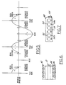
- one cylinder of a multi-cylinder, four-stroke cycle reciprocating internal combustion engine 10 has crankshaft 12 with connecting rod 14 and piston 16. Air flows into the cylinder past intake port throttle 28 and through intake port 18 and then past intake valve 20. Exhaust gases exit the cylinder through exhaust port 22 after flowing past exhaust valve 24. Exhaust valve 24 is operated by exhaust camshaft 26. As may be seen in Figure 1, ingress of air into the engine may be stopped by closing intake port throttle 28 entirely; when port throttle 28 is closed, air will not be allowed to enter the individual cylinder associated with the port throttle, even if intake valve 20 is allowed to open and close in normal fashion. A combination of port throttle 28 and the adjustment of timing of exhaust camshaft 26, will produce cylinder pressure histories of the types shown in Figures 4 and 5.
- FIG. 2 illustrates a control system according to the present invention.
- Controller 30 receives a variety of inputs from engine operating sensors 32 which include many of the types of sensors known to those skilled in the art of engine control and suggested by this disclosure. Accordingly, sensors 32 may include engine speed, engine load, intake manifold absolute pressure, engine intake air mass flow rate, engine temperature, vehicle speed, vehicle gear selection, throttle position, accelerator position, and other parameters known to those skilled in the art and suggested by this disclosure. The fact remains that there are many conditions in which it is desirable to operate an engine in less than the maximum number of cylinders, and, as noted above, the purpose of the present invention is to allow such fractional operation.
- controller 30, which may comprise an electronic engine operating controller drawn from many of the types known to those skilled in the art of automotive electronic engine controllers, is connected with camshaft phaser 34 and port throttles 28.
- Controller 30 operates an engine according to the present invention by sensing a plurality of engine and vehicle operating parameters, including at least engine load and engine speed. Other parameters which could be used include, without limitation, vehicle speed, throttle position, and other parameters known to those skilled in the art and suggested by this disclosure. Controller 30 compares the sensed operating parameters with predetermined threshold values. For example, in a typical control algorithm, cylinder deactivation would not be used unless engine speed exceeded a minimum threshold value and engine load was less than a minimum threshold value. In this sense, the term “exceed” is used herein to mean that the value of the sensed parameter may either be greater than or less than the threshold value.
- controller 30 will command camshaft phaser 34 to move to adjust the timing of camshaft 26 which operates exhaust valves 24 to achieve the timing shown in either Figure 4 or Figure 5.
- the position of maximum exhaust valve lift is moved from approximately 90° before TDC on the exhaust stroke to a point in which maximum lift occurs either at TDC of the exhaust stroke, or at BDC of the expansion stroke. In either case, pressure within the cylinder will be maintained approximately at atmospheric level during the time in which the exhaust valve is open.
- Figure 5 illustrates an alternative method in which exhaust valve timing is advanced about 70 crankshaft degrees from normal timing.
- the exhaust valve opens symmetrically about BDC on the expansion stroke and closes well into the exhaust stroke, with the result that pressure within the cylinder is maintained at roughly an atmospheric level between the points at which the exhaust valve opens and closes, and only minimal pressure builds up in the cylinder thereafter, with the pressure build-up being symmetrical about TDC during the O/L position, with an expansion occurring to a sub-atmospheric pressure during the intake stroke, followed by recompression of the air in the cylinder during the compression stroke.
- exhaust camshaft timing control may be used for beneficial operation in terms of decreased emissions and increased fuel economy, even while the engine is operated in all of the cylinders. Accordingly, the total cost of the hardware needed to operate an engine according to the present invention need not be borne solely by the need for achieving fractional operation of the engine. Yet another advantage of the present system resides in the fact that because the peak pressure achieved in the deactivated cylinders is less than the peak pressure achieved with prior art valve disabling systems, the motoring loss of the deactivated cylinders will be less, with the result that fuel economy will be enhanced.
- FIG. 6 is a schematic representation of a V-type of engine -- in this case, a V-6 -- having a system according to the present invention.
- camshaft 42 comprises a single camshaft for one bank of cylinders of the engine, with camshaft 42 operating both intake and exhaust valves.
- the bank of cylinders associated with camshaft 42 may be deactivated by single camshaft phaser 34 (not shown) which would be applied to one end of camshaft 42.
- intake camshaft 44 and exhaust camshaft 46 on the opposite bank of engine cylinders could be driven independently by crankshaft 12, or, alternatively, a camshaft phaser 34 could be applied to exhaust camshaft 46 according to the present invention.
- camshaft phaser 34 is controlled by controller 30 and will advance or retard the camshaft as commanded by controller 30 to achieve operation of the engine with disabled cylinders according to the present invention.
- each port throttle 28 and its accompanying intake valve 20 should be less than approximately 20% of the displaced volume of the cylinder to prevent a diminution of the efficacy of closing the port throttle due to the throttling loss due to the partially opened intake valve as the trapped charge lying between the port throttle is alternatively compressed and expanded.
Landscapes
- Engineering & Computer Science (AREA)
- Chemical & Material Sciences (AREA)
- Combustion & Propulsion (AREA)
- Mechanical Engineering (AREA)
- General Engineering & Computer Science (AREA)
- Output Control And Ontrol Of Special Type Engine (AREA)
Claims (12)
- Mehrzylindrige Viertakt-Hubkolben-Brennkraftmaschine mit einer Kurbelwelle (12) und mehreren, in mehreren Zylindern hin- und hergehend gelagerten Kolben (16),dadurch gekennzeichnet, daß besagte Brennkraftmaschine (10) außerdem folgendes aufweist:wenigstens einem Einlaß-Tellerventil (20) und wenigstens einem Auslaß-Tellerventil (24) für jeden Zylinder des Motors,einer Nockenwelle (26) zur Betätigung wenigstens der Auslaßventile (24),einen Phasensteuermechanismus (34) für die Nockenwelle zum Antrieb besagter Nockenwelle (26) und zur Einstellung der Steuerzeiten der Nockenwelle (26) in bezug auf die Drehstellung der Kurbelwelle (12);mehrere Einlaßdrosseln (28), wobei eine der besagten Drosseln in der Nähe und stromoberhalb eines jeden der besagten Einlaßventile (20) angeordnet ist; undeine mit besagten Einlaßdrosseln (28) und besagtem Phasensteuermechanismus (34) für die Nockenwelle verbundene Steuerung (30) zur Abschaltung wenigstens einiger der Zylinder durch Betätigen des Phasensteuermechanismus (34) der Nockenwelle und besagter Einlaßdrosseln (28) derart, daß für jeden abzuschaltenden Zylinder die Einlaßdrossel (28) geschlossen und die Nockenwellensteuerung derart eingestellt wird, daß die Position mit dem größten Auslaßventilhub von etwa 90° vor dem oberen Totpunkt im Auspuffhub auf einen Punkt verschoben wird, bei dem der größte Ventilhub entweder ungefähr im oberen Totpunkt des Auspuffhubes auftritt oder ungefähr im unteren Totpunkt des Expansionshubes.
- Brennkraftmaschine nach Anspruch 1, in welcher sich das Auslaßventil vorzugsweise in etwa über den gleichen Drehwinkelbereich der Kurbelwelle um die untere Totpunktlage des Kolbens am Ende des Expansionshubes öffnet und schließt.
- Brennkraftmaschine nach Anspruch 1, in welcher sich das Auslaßventil vorzugsweise in etwa über den gleichen Drehwinkelbereich der Kurbelwelle um die obere Totpunktlage des Kolbens am Ende des Auspuffhubes öffnet und schließt.
- Brennkraftmaschine nach Anspruch 1, in welcher besagte Steuerung den besagten Phasensteuermechanismus der Nockenwelle derart betätigt, daß die Auslaßnockenwelle um etwa 110 Grad Kurbelwellendrehung gegenüber ihrer normalen Betriebslage verspätet eingestellt wird.
- Brennkraftmaschine nach Anspruch 1, in welcher besagte Steuerung den besagten Phasensteuermechanismus der Nockenwelle derart betätigt, daß die Auslaßnockenwelle um etwa 70 Grad Kurbelwellendrehung gegenüber ihrer normalen Betriebslage vorverstellt wird.
- Brennkraftmaschine nach Anspruch 1, in welcher besagter Motor ein V-Motor mit zwei Zylinderreihen ist, wobei jede Zylinderreihe eine separate Auslaßnockenwelle und einen ihr zugeordneten Nockenwellen-Phasensteuermechanismus aufweist, wobei besagte Steuerung den besagten Nockenwellen-Phasensteuermechanismus und die Einlaßdrosseln einer der beiden Zylinderreihen derart betätigt, daß diese Zylinderreihe abgeschaltet wird.
- Brennkraftmaschine nach Anspruch 1, in welcher besagter Motor ein V-Motor mit zwei Zylinderreihen ist, wobei jede Zylinderreihe eine einzige Nockenwelle sowohl für die Einlaß- als auch für die Auslaßventile und einen ihr zugeordneten Nockenwellen-Phasensteuermechanismus aufweist, wobei besagte Steuerung den besagten Nockenwellen-Phasensteuermechanismus und die Einlaßdrosseln einer der beiden Zylinderreihen derart betätigt, daß alle Zylinder dieser Zylinderreihe abgeschaltet werden.
- Brennkraftmaschine nach Anspruch 1, in welcher besagter Motor ein Reihenmotor mit einer vorderen Zylindergruppe und einer hinteren Zylindergruppe ist, wobei jede Zylindergruppe eine separate Auslaßnockenwelle und einen ihr zugeordneten Nockenwellen-Phasensteuermechanismus aufweist, wobei besagte Steuerung den Phasensteuermechanismus und die Einlaßdrosseln einer der besagten Zylindergruppen derart betätigt, daß diese Gruppe abgeschaltet wird.
- Brennkraftmaschine nach Anspruch 1, in welcher besagter Motor ein Reihenmotor mit einer vorderen Zylindergruppe und einer hinteren Zylindergruppe ist, wobei jede Zylindergruppe eine einzige Nockenwelle sowohl für die Einlaß- als auch für die Auslaßventile und einen ihr zugeordneten Nockenwellen-Phasensteuermechanismus aufweist, wobei besagte Steuerung den Phasensteuermechanismus und die Einlaßdrosseln einer der besagten Zylindergruppen derart betätigt, daß alle Zylinder dieser Gruppe abgeschaltet werden.
- Verfahren zum Betreiben einer Mehrzylinder-Viertakt-Hubkolben-Brennkraftmaschine mit weniger als der maximalen Zylinderzahl, welches folgende Schritte aufweist:Erfassung mehrerer Motorbetriebsparameter, welche wenigstens die Motorlast und die Motordrehzahl einschließen;Vergleichen der erfaßten Betriebsparameter mit vorbestimmten Schwellenwerten;Ausgabe eines Teilbetriebsbefehles, wenn die erfaßten Parameter die Schwellenwerte überschreiten;Schließen der Einlaßdrosseln in jedem der abzuschaltenden Zylinder in Reaktion auf den Teilbetriebsbefehl; undVerstellen der Steuerzeiten der Nockenwelle, welche die Auslaß-Tellerventile der abzuschaltenden Zylinder betätigt, so daß die Lage des größten Auslaßventilhubes von etwa 90° vor OT im Auspuffhub auf einen Punkt verschoben wird, in welchem der größte Ventilhub in OT des Auspuffhubes vorliegt.
- Verfahren nach Anspruch 10, außerdem den Schritt der Abschaltung der Kraftstoffzufuhr zu den abgeschalteten Zylindern beinhaltend.
- Verfahren nach Anspruch 10, in welchem besagte Einlaßdrosseln gleichzeitig mit dem Verstellen der Steuerzeiten der besagten Nockenwelle geschlossen werden.
Applications Claiming Priority (2)
| Application Number | Priority Date | Filing Date | Title |
|---|---|---|---|
| US407523 | 1995-03-16 | ||
| US08/407,523 US5467748A (en) | 1995-03-16 | 1995-03-16 | Internal combustion engine with intake port throttling and exhaust camshaft phase shifting for cylinder deactivation |
Publications (2)
| Publication Number | Publication Date |
|---|---|
| EP0732489A1 EP0732489A1 (de) | 1996-09-18 |
| EP0732489B1 true EP0732489B1 (de) | 1998-11-11 |
Family
ID=23612430
Family Applications (1)
| Application Number | Title | Priority Date | Filing Date |
|---|---|---|---|
| EP96300912A Expired - Lifetime EP0732489B1 (de) | 1995-03-16 | 1996-02-09 | Verstellung der Nockenwellenphase für Zylinderabschaltung |
Country Status (4)
| Country | Link |
|---|---|
| US (1) | US5467748A (de) |
| EP (1) | EP0732489B1 (de) |
| CA (1) | CA2168913A1 (de) |
| DE (1) | DE69600937T2 (de) |
Cited By (1)
| Publication number | Priority date | Publication date | Assignee | Title |
|---|---|---|---|---|
| DE10159758A1 (de) * | 2001-12-05 | 2003-07-24 | Daimler Chrysler Ag | Verfahren zum Betrieb einer mehrzylindrigen Brennkraftmaschine |
Families Citing this family (41)
| Publication number | Priority date | Publication date | Assignee | Title |
|---|---|---|---|---|
| US5642703A (en) * | 1995-10-16 | 1997-07-01 | Ford Motor Company | Internal combustion engine with intake and exhaust camshaft phase shifting for cylinder deactivation |
| EP0854273A1 (de) | 1997-01-21 | 1998-07-22 | Ford Global Technologies, Inc. | Variable Ventilzeitsteuerung und variable Ventilhube für Brennkraftmaschine |
| US5934263A (en) * | 1997-07-09 | 1999-08-10 | Ford Global Technologies, Inc. | Internal combustion engine with camshaft phase shifting and internal EGR |
| US5950582A (en) * | 1998-06-08 | 1999-09-14 | Ford Global Technologies, Inc. | Internal combustion engine with variable camshaft timing and intake valve masking |
| US5957096A (en) * | 1998-06-09 | 1999-09-28 | Ford Global Technologies, Inc. | Internal combustion engine with variable camshaft timing, charge motion control valve, and variable air/fuel ratio |
| US5960755A (en) * | 1998-06-09 | 1999-10-05 | Ford Global Technologies, Inc. | Internal combustion engine with variable camshaft timing and variable duration exhaust event |
| US6161521A (en) * | 1998-11-04 | 2000-12-19 | Ford Global Technologies, Inc. | Internal combustion engine having deceleration fuel shut off and camshaft controlled charge trapping |
| JP3733786B2 (ja) * | 1999-05-21 | 2006-01-11 | トヨタ自動車株式会社 | 電磁駆動弁を有する内燃機関 |
| US6237559B1 (en) * | 2000-03-29 | 2001-05-29 | Ford Global Technologies, Inc. | Cylinder deactivation via exhaust valve deactivation and intake cam retard |
| DE10055595A1 (de) * | 2000-11-09 | 2002-05-29 | Ina Schaeffler Kg | Verfahren und Vorrichtung zur Zylinderabschaltung bei Verbrennungsmotoren |
| US20020123401A1 (en) | 2001-03-02 | 2002-09-05 | Henry Rassem Ragheb | Combination starter-generator |
| US6647947B2 (en) | 2002-03-12 | 2003-11-18 | Ford Global Technologies, Llc | Strategy and control system for deactivation and reactivation of cylinders of a variable displacement engine |
| US6962143B2 (en) * | 2003-07-16 | 2005-11-08 | Southwest Research Institute | High-efficiency, low emission gasoline engines for heavy-duty applications |
| US8327619B2 (en) * | 2005-09-12 | 2012-12-11 | Volvo Lastvagnar Ab | Method for operating an internal combustion engine |
| FR2893676B1 (fr) * | 2005-11-24 | 2008-01-04 | Inst Francais Du Petrole | Procede pour controler l'admission et/ou l'echappement d'au moins un cylindre desactive d'un moteur a combustion interne |
| US20080185194A1 (en) * | 2007-02-02 | 2008-08-07 | Ford Global Technologies, Llc | Hybrid Vehicle With Engine Power Cylinder Deactivation |
| US7866292B2 (en) * | 2008-03-26 | 2011-01-11 | AES Industries Inc | Apparatus and methods for continuous variable valve timing |
| US8457862B2 (en) * | 2008-06-13 | 2013-06-04 | Delphi Technologies, Inc. | Method for controlling and diagnosing a vane-type cam phaser having intermediate position pin locking |
| FR2939476A1 (fr) * | 2008-12-10 | 2010-06-11 | Inst Francais Du Petrole | Procede pour controler le fonctionnement d'un moteur a combustion interne avec desactivation d'au moins un cylindre |
| DE102009060211A1 (de) | 2009-12-23 | 2011-06-30 | MAHLE International GmbH, 70376 | Brennkraftmaschine und zugehöriges Betriebsverfahren |
| US8651075B2 (en) | 2010-12-08 | 2014-02-18 | GM Global Technology Operations LLC | Engine assembly including camshaft with independent cam phasing |
| US8467927B2 (en) * | 2011-11-03 | 2013-06-18 | Ford Global Technologies, Llc | Method and system for speed control of a hybrid vehicle |
| US8467926B2 (en) | 2011-11-03 | 2013-06-18 | Ford Global Technologies, Llc | Method and system for valve operation control |
| DE102012206372A1 (de) | 2012-04-18 | 2013-10-24 | Bayerische Motoren Werke Aktiengesellschaft | Mengengeregelte 4-Takt-Hubkolben-Brennkraftmaschine und Verfahren zum Betrieb der 4-Takt-Hubkolben-Brennkraftmaschine |
| US9145822B2 (en) * | 2012-07-16 | 2015-09-29 | Ford Global Technologies, Llc | Method and device for controlling a four-stroke internal combustion engine |
| US10619584B2 (en) | 2016-06-02 | 2020-04-14 | Tula Technology, Inc. | Dynamic valve control in a skip fire controlled engine |
| US11261807B2 (en) | 2012-07-31 | 2022-03-01 | Tula Technology, Inc. | Dynamic valve control in a skip fire controlled engine |
| US9109507B2 (en) | 2012-10-18 | 2015-08-18 | GM Global Technology Operations LLC | Engine assembly with variable valve displacement on one cylinder bank and method of controlling same |
| DE102012022800A1 (de) | 2012-11-21 | 2014-05-22 | Volkswagen Aktiengesellschaft | Nockenwelle mit einer Innenwelle und einer Außenwelle |
| US9010300B2 (en) * | 2013-06-27 | 2015-04-21 | GM Global Technology Operations LLC | Reduced torque variation for engines with active fuel management |
| WO2015035133A1 (en) * | 2013-09-06 | 2015-03-12 | Cummins Inc. | Thermal management of exhaust gas via cylinder deactivation |
| US11236689B2 (en) | 2014-03-13 | 2022-02-01 | Tula Technology, Inc. | Skip fire valve control |
| US9976500B2 (en) | 2014-10-20 | 2018-05-22 | Ford Global Technologies, Llc | Method and system for selective cylinder deactivation |
| US11578672B2 (en) * | 2016-08-17 | 2023-02-14 | Eaton Intelligent Power Limited | Friction mitigation in cylinder deactivation |
| US10364739B2 (en) | 2016-09-01 | 2019-07-30 | Bright Acceleration Technologies LLC | Synergistic induction and turbocharging in internal combustion engine systems |
| US10697357B2 (en) | 2016-09-01 | 2020-06-30 | Bright Acceleration Technologies LLC | Cross-port air flow to reduce pumping losses |
| US10107215B2 (en) | 2016-09-01 | 2018-10-23 | Bright Acceleration Technologies LLC | Synergistic induction and turbocharging in internal combustion engine systems |
| US9638095B1 (en) | 2016-09-01 | 2017-05-02 | Bright Acceleration Technologies LLC | Synergistic induction and turbocharging in internal combustion engine systems |
| CN110637153B (zh) * | 2017-05-18 | 2022-04-05 | 图拉技术公司 | 跳过点火式控制的发动机中的动态气门控制 |
| US11181017B2 (en) * | 2020-03-26 | 2021-11-23 | Ford Global Technologies, Llc | System and method for maintaining a temperature of an emission device |
| US11306672B2 (en) | 2020-05-22 | 2022-04-19 | Tula Technology, Inc. | Use of different pneumatic cylinder spring types in a variable displacement engine for engine and aftertreatment system temperature control |
Family Cites Families (12)
| Publication number | Priority date | Publication date | Assignee | Title |
|---|---|---|---|---|
| FR1515767A (fr) * | 1966-10-20 | 1968-03-01 | Dispositif corrigeant automatiquement la distribution dans les moteurs à quatre temps | |
| JPS5951667B2 (ja) * | 1979-06-22 | 1984-12-15 | 日産自動車株式会社 | 気筒数制御エンジン |
| JPS5672234A (en) * | 1979-11-15 | 1981-06-16 | Nissan Motor Co Ltd | Cylinder number controlled engine |
| US4401069A (en) * | 1981-02-10 | 1983-08-30 | Foley James E | Camshaft lobes which provide selective cylinder cutout of an internal combustion engine |
| DE3316446A1 (de) * | 1982-05-07 | 1983-11-10 | Nissan Motor Co., Ltd., Yokohama, Kanagawa | Vierzylinder-verbrennungsmotor |
| JPS58176428A (ja) * | 1982-09-30 | 1983-10-15 | Nissan Motor Co Ltd | 気筒数制御エンジン |
| US4499870A (en) * | 1983-04-26 | 1985-02-19 | Nissan Motor Company, Limited | Multi-cylinder internal combustion engine |
| JPS6045740A (ja) * | 1983-08-23 | 1985-03-12 | Mazda Motor Corp | 気筒数制御エンジンの回転数検出装置 |
| JPS60150411A (ja) * | 1984-01-18 | 1985-08-08 | Mazda Motor Corp | 気筒数制御エンジン |
| JP2741266B2 (ja) * | 1989-12-18 | 1998-04-15 | マツダ株式会社 | エンジンの吸排気制御装置 |
| US5190013A (en) * | 1992-01-10 | 1993-03-02 | Siemens Automotive L.P. | Engine intake valve selective deactivation system and method |
| EP0583583B1 (de) * | 1992-07-16 | 1996-09-04 | Mitsubishi Jidosha Kogyo Kabushiki Kaisha | Kraftwagenbrennkraftmaschine |
-
1995
- 1995-03-16 US US08/407,523 patent/US5467748A/en not_active Expired - Fee Related
-
1996
- 1996-02-06 CA CA002168913A patent/CA2168913A1/en not_active Abandoned
- 1996-02-09 DE DE69600937T patent/DE69600937T2/de not_active Expired - Fee Related
- 1996-02-09 EP EP96300912A patent/EP0732489B1/de not_active Expired - Lifetime
Cited By (1)
| Publication number | Priority date | Publication date | Assignee | Title |
|---|---|---|---|---|
| DE10159758A1 (de) * | 2001-12-05 | 2003-07-24 | Daimler Chrysler Ag | Verfahren zum Betrieb einer mehrzylindrigen Brennkraftmaschine |
Also Published As
| Publication number | Publication date |
|---|---|
| DE69600937D1 (de) | 1998-12-17 |
| US5467748A (en) | 1995-11-21 |
| DE69600937T2 (de) | 1999-04-01 |
| EP0732489A1 (de) | 1996-09-18 |
| CA2168913A1 (en) | 1996-09-17 |
Similar Documents
| Publication | Publication Date | Title |
|---|---|---|
| EP0732489B1 (de) | Verstellung der Nockenwellenphase für Zylinderabschaltung | |
| US5642703A (en) | Internal combustion engine with intake and exhaust camshaft phase shifting for cylinder deactivation | |
| US5934263A (en) | Internal combustion engine with camshaft phase shifting and internal EGR | |
| US6647947B2 (en) | Strategy and control system for deactivation and reactivation of cylinders of a variable displacement engine | |
| US6161521A (en) | Internal combustion engine having deceleration fuel shut off and camshaft controlled charge trapping | |
| US6523504B2 (en) | Control system for controlling variable valve type internal combustion engine | |
| US7162996B2 (en) | Engine braking methods and apparatus | |
| US6622689B2 (en) | Method and system for controlling auto-ignition in an internal combustion engine | |
| US6553962B1 (en) | Exhaust valve deactivation and intake valve phasing to enable deceleration fuel shut off and engine braking | |
| US6561145B1 (en) | Torque control method and system in an engine with a fully variable intake valve | |
| US5918577A (en) | Stratified exhaust residual engine | |
| US7628136B2 (en) | Engine control with cylinder deactivation and variable valve timing | |
| US6237559B1 (en) | Cylinder deactivation via exhaust valve deactivation and intake cam retard | |
| US4860709A (en) | Engine induction system and method | |
| US12247502B2 (en) | Multi-cylinder internal combustion engine, with cylinders equipped with intake valve variable actuation systems having hydraulic circuits which cross each other | |
| US6269793B1 (en) | Internal combustion engine having deceleration fuel shut off and camshaft controlled charge trapping | |
| US7290524B2 (en) | Control apparatus and method for four-stroke premixed compression ignition internal combustion engine | |
| WO2007018255A1 (en) | Internal combustion engine | |
| US6216667B1 (en) | Method and device for a supercharged engine brake | |
| GB2119853A (en) | Four-cylinder I.C. engine operable with two effective cylinders | |
| WO1996001939A1 (en) | A restricted induction reciprocating piston type internal combustion engine | |
| EP0636777B1 (de) | Viertaktbrennkraftmaschine | |
| EP1803913A2 (de) | Motorbremsverfahren und Einrichtung | |
| US20170306869A1 (en) | Diesel engine and method for starting a diesel engine | |
| EP1063392A2 (de) | Brennkraftmaschine für Kraftfahrzeuge |
Legal Events
| Date | Code | Title | Description |
|---|---|---|---|
| PUAI | Public reference made under article 153(3) epc to a published international application that has entered the european phase |
Free format text: ORIGINAL CODE: 0009012 |
|
| AK | Designated contracting states |
Kind code of ref document: A1 Designated state(s): DE FR GB |
|
| 17P | Request for examination filed |
Effective date: 19961111 |
|
| 17Q | First examination report despatched |
Effective date: 19970602 |
|
| GRAG | Despatch of communication of intention to grant |
Free format text: ORIGINAL CODE: EPIDOS AGRA |
|
| GRAG | Despatch of communication of intention to grant |
Free format text: ORIGINAL CODE: EPIDOS AGRA |
|
| GRAH | Despatch of communication of intention to grant a patent |
Free format text: ORIGINAL CODE: EPIDOS IGRA |
|
| GRAH | Despatch of communication of intention to grant a patent |
Free format text: ORIGINAL CODE: EPIDOS IGRA |
|
| GRAA | (expected) grant |
Free format text: ORIGINAL CODE: 0009210 |
|
| AK | Designated contracting states |
Kind code of ref document: B1 Designated state(s): DE FR GB |
|
| REF | Corresponds to: |
Ref document number: 69600937 Country of ref document: DE Date of ref document: 19981217 |
|
| ET | Fr: translation filed | ||
| PLBE | No opposition filed within time limit |
Free format text: ORIGINAL CODE: 0009261 |
|
| STAA | Information on the status of an ep patent application or granted ep patent |
Free format text: STATUS: NO OPPOSITION FILED WITHIN TIME LIMIT |
|
| 26N | No opposition filed | ||
| REG | Reference to a national code |
Ref country code: FR Ref legal event code: TP Ref country code: FR Ref legal event code: CD |
|
| REG | Reference to a national code |
Ref country code: GB Ref legal event code: IF02 |
|
| PGFP | Annual fee paid to national office [announced via postgrant information from national office to epo] |
Ref country code: GB Payment date: 20040107 Year of fee payment: 9 |
|
| PGFP | Annual fee paid to national office [announced via postgrant information from national office to epo] |
Ref country code: FR Payment date: 20040202 Year of fee payment: 9 |
|
| PGFP | Annual fee paid to national office [announced via postgrant information from national office to epo] |
Ref country code: DE Payment date: 20040227 Year of fee payment: 9 |
|
| PG25 | Lapsed in a contracting state [announced via postgrant information from national office to epo] |
Ref country code: GB Free format text: LAPSE BECAUSE OF NON-PAYMENT OF DUE FEES Effective date: 20050209 |
|
| PG25 | Lapsed in a contracting state [announced via postgrant information from national office to epo] |
Ref country code: DE Free format text: LAPSE BECAUSE OF NON-PAYMENT OF DUE FEES Effective date: 20050901 |
|
| GBPC | Gb: european patent ceased through non-payment of renewal fee |
Effective date: 20050206 |
|
| PG25 | Lapsed in a contracting state [announced via postgrant information from national office to epo] |
Ref country code: FR Free format text: LAPSE BECAUSE OF NON-PAYMENT OF DUE FEES Effective date: 20051031 |
|
| REG | Reference to a national code |
Ref country code: FR Ref legal event code: ST Effective date: 20051031 |
|
| REG | Reference to a national code |
Ref country code: FR Ref legal event code: CD Ref country code: FR Ref legal event code: CA |