EP1176420B1 - Method and apparatus for inspecting components - Google Patents
Method and apparatus for inspecting components Download PDFInfo
- Publication number
- EP1176420B1 EP1176420B1 EP01306415A EP01306415A EP1176420B1 EP 1176420 B1 EP1176420 B1 EP 1176420B1 EP 01306415 A EP01306415 A EP 01306415A EP 01306415 A EP01306415 A EP 01306415A EP 1176420 B1 EP1176420 B1 EP 1176420B1
- Authority
- EP
- European Patent Office
- Prior art keywords
- eddy current
- component
- coils
- primary
- area
- Prior art date
- Legal status (The legal status is an assumption and is not a legal conclusion. Google has not performed a legal analysis and makes no representation as to the accuracy of the status listed.)
- Expired - Lifetime
Links
- 238000000034 method Methods 0.000 title claims description 13
- 238000007689 inspection Methods 0.000 claims description 20
- 239000000758 substrate Substances 0.000 claims description 16
- 230000001939 inductive effect Effects 0.000 claims description 3
- 238000007789 sealing Methods 0.000 claims 1
- 239000000523 sample Substances 0.000 description 7
- 239000002828 fuel tank Substances 0.000 description 3
- 239000000853 adhesive Substances 0.000 description 2
- 230000001070 adhesive effect Effects 0.000 description 2
- 239000000463 material Substances 0.000 description 2
- 229920003223 poly(pyromellitimide-1,4-diphenyl ether) Polymers 0.000 description 2
- RYGMFSIKBFXOCR-UHFFFAOYSA-N Copper Chemical compound [Cu] RYGMFSIKBFXOCR-UHFFFAOYSA-N 0.000 description 1
- 239000002390 adhesive tape Substances 0.000 description 1
- XAGFODPZIPBFFR-UHFFFAOYSA-N aluminium Chemical compound [Al] XAGFODPZIPBFFR-UHFFFAOYSA-N 0.000 description 1
- 229910052782 aluminium Inorganic materials 0.000 description 1
- 229910052802 copper Inorganic materials 0.000 description 1
- 239000010949 copper Substances 0.000 description 1
- 238000005336 cracking Methods 0.000 description 1
- 230000005674 electromagnetic induction Effects 0.000 description 1
- 230000001681 protective effect Effects 0.000 description 1
- 239000000565 sealant Substances 0.000 description 1
Images

Classifications
-
- G—PHYSICS
- G01—MEASURING; TESTING
- G01N—INVESTIGATING OR ANALYSING MATERIALS BY DETERMINING THEIR CHEMICAL OR PHYSICAL PROPERTIES
- G01N27/00—Investigating or analysing materials by the use of electric, electrochemical, or magnetic means
- G01N27/72—Investigating or analysing materials by the use of electric, electrochemical, or magnetic means by investigating magnetic variables
- G01N27/82—Investigating or analysing materials by the use of electric, electrochemical, or magnetic means by investigating magnetic variables for investigating the presence of flaws
- G01N27/90—Investigating or analysing materials by the use of electric, electrochemical, or magnetic means by investigating magnetic variables for investigating the presence of flaws using eddy currents
- G01N27/9006—Details, e.g. in the structure or functioning of sensors
Definitions
- the present invention relates generally to eddy current inspection, and more particularly to components having permanently affixed eddy current elements.
- Eddy current inspection is commonly used to detect flaws in electrically conductive components such as aluminum aircraft fuel tanks. Electromagnetic induction is used in this type of inspection to induce eddy currents in the component being inspected.
- a probe having one or more coils is used to generate alternating magnetic fields which induce the eddy currents in the component.
- the altered eddy currents produce changes in a secondary magnetic field which are detected by the probe.
- the probe generates an electrical signal in response to the altered secondary magnetic field. The amplitude and phase of the electrical signal is generally proportionate to the size of the flaw.
- a probe having one or more coils was used in the past to perform the inspections.
- the probe was positioned adjacent to the surface being inspected.
- Using a probe to inspect interior surfaces of components such as bulkheads forming fuel tanks inside aircraft wings required disassembly of the structure to position the probe adjacent the surface.
- disassembly, inspection and reassembly can take several hours, days, weeks or longer. During this time, the structure is unavailable. Further, the cost of labor required to perform these tasks can be high. Accordingly, a need exists for a method and apparatus for performing eddy current inspection of interior surfaces of complex structures without disassembling the structures.
- GB 886,247 discloses a method of periodically measuring the impedance of coils built into washers or gaskets to ascertain whether any cracking or physical change has been produced in a structure into which the coils are incorporated.
- the present invention provides a method of inspecting a preselected area of an electrically conductive component to determine whether flaws are present therein.
- the method comprises the steps of permanently mounting an eddy current element comprising a plurality of eddy current coils arranged on the component over the preselected area and energizing the element to generate alternating magnetic fields proximate the component thereby inducing eddy currents in the component
- An electrical signal generated by a secondary magnetic field formed proximate the component by the eddy currents is detected by the element, and the detected electrical signal is compared to a reference signal to determine whether the detected signal is different than the reference signal, the reference signal being generated by a plurality of coils on the component in a reference location known to be free of flaws. A difference in the signals indicates a flaw is present in the component.
- the further method comprises attaching a conduit to the component.
- a lead is attached to each primary and reference eddy current elements, the leads are bundled and threaded through the conduit for selectively connecting the eddy current element to remote eddy current inspection equipment.
- a further aspect of the present invention provides an electrically conductive component having an area selected for inspection in combination with apparatus for detecting flaws in the selected area of the component.
- the apparatus comprises the features disclosed in claim 4.
- an electrically conductive component such as a portion of a bulkhead used to form an aircraft fuel tank is generally designated by the reference number 10.
- the component 10 is conventional in all respects and will not be described in further detail.
- inspection apparatus (generally designated by 12) is mounted on the component 10 for detecting flaws (e.g., a crack 14) in a preselected area 16 of the component.
- flaws e.g., a crack 14
- a preselected area 16 of the component e.g., a crack 14
- the apparatus 12 may be positioned over each critical portion of the component or those portions which are particularly susceptible to failure. Further, the entire component 10 (or those portions which are inspectible by eddy current inspection) may be covered by the apparatus 12 without departing from the scope of the present invention.
- the apparatus 12 includes a substrate 20 sized and shaped for covering the preselected area 16 of the component 10.
- the substrate 20 of the preferred embodiment is rectangular, having a width of about 12.5 mm and a length of about 112.5 mm.
- the substrate 20 of the preferred embodiment is a sheet of Kapton tape has an adhesive backing for attaching the substrate to the component 10 over the preselected area 16.
- Kapton is a U.S. federally registered trademark of E. I. du Pont de Nemours and Company of Wilmington, Delaware.
- a separate adhesive tape (not shown) may be used to attach the substrate 20 to the component 10.
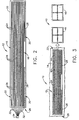
- a primary eddy current element, generally designated by 22, comprising several eddy current coils 24 is mounted on the substrate 20 (Fig. 2).
- the primary element 22 of the preferred embodiment has an array of coils formed by nine rows of coils containing three overlapping coils each.
- each of the coils of the preferred embodiment is rectangular, having a width of about 0.75 mm and a length of about 42.5 mm.
- the element 22 of the preferred embodiment is sized and shaped for covering at least a portion of the preselected area 16 to detect flaws in the component.
- the coils 24 in each row of the preferred embodiment are overlapped by a distance of about 7.5 mm.
- the coils may be made of other materials and by other processes without departing from the scope of the present invention, the coils of the preferred embodiment are copper and are etched in the substrate by a conventional photolithographic process.
- a reference eddy current element 26 comprising eddy current coils 28 is mounted on the substrate 20 below the lowermost row of primary eddy current coils 24.
- the primary eddy current element 22 and the reference eddy current element 26 are spaced from the component 10 by the substrate 20, these elements are spaced from the component by a substantially equal and constant distance (i.e., the thickness of the substrate).
- the reference element 26 of the preferred embodiment has two separated coils 28 positioned over a reference area 30 (Fig. 1) of the component 10 located outside the area selected for inspection 16.
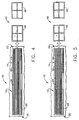
- Instrumentation leads 32 are connected to each primary coil 24 and each reference coil 28 as shown in Fig. 2. These leads 32 are bundled and fed through a protective tube or conduit 34 leading to an electrical connector 36 positioned for access by technicians to selectively connect the primary element 22 and reference element 26 to conventional eddy current equipment (generally designated by 40 in Fig. 3).
- the tube 34 may have other configurations without departing from the scope of the present invention, in one preferred embodiment the tube is a cylindrical tube having an outer diameter of about 5 mm. Further, although other means of attaching the tube 34 to the component may be used without departing from the scope of the present invention, in one embodiment the tube is attached to the component with a suitable conventional adhesive.
- Holes and/or grooves or other openings may be formed in low stress regions of the component 10 to accommodate the tube 34. Further, the ends of the tube 34 may be sealed with a suitable conventional sealant to prevent contaminates from entering the tube and component 10. Still further, it is envisioned that openings may be formed in the side of the tube 34 to provide access for the leads 32.
- the apparatus 12 described above may be used to inspect a preselected area 16 of an electrically conductive component 10 to determine whether flaws (e.g., a crack 14) are present.
- a preselected area 16 of an electrically conductive component 10 to determine whether flaws (e.g., a crack 14) are present.
- an eddy current element 22 is permanently mounted on the component 10 over the preselected area 16.
- conventional eddy current equipment 40 is connected to the element 22 using the connector 36.
- the equipment 40 energizes the element 22 to generate alternating magnetic fields proximate the component 10 thereby inducing eddy currents in the component.
- the element 22 detects an electrical signal generated by a secondary magnetic field formed proximate the component 10 by the eddy currents.
- the detected electrical signal is compared to the preference signal to determine whether the detected signal is different than the reference signal. Such a difference indicates the presence of a flaw 14 in the component 10.
- the electrical signals received by the primary coils are equal to the reference signals received by the reference coils 28.
- the impedance of coil 42 is compared to the impedance of the reference coils 28 on a corresponding display 46 of the eddy current equipment 40
- the difference is zero.
- the impedance of coil 44 is compared to the impedance of the reference coils 28 on a corresponding display 48 of the eddy current equipment 40
- the difference is zero.
- the display 46 shows a difference in impedance between coil 42 and coils 28.
- the corresponding display 48 displays a null reading. As the crack grows longer as shown in Fig. 5, displays 46 and 48 both show a difference in impedance between the respective coils. Thus, the location and the length of any flaws may be detected using the apparatus 12 and method described above.
Landscapes
- Chemical & Material Sciences (AREA)
- Chemical Kinetics & Catalysis (AREA)
- Electrochemistry (AREA)
- Physics & Mathematics (AREA)
- Health & Medical Sciences (AREA)
- Life Sciences & Earth Sciences (AREA)
- Analytical Chemistry (AREA)
- Biochemistry (AREA)
- General Health & Medical Sciences (AREA)
- General Physics & Mathematics (AREA)
- Immunology (AREA)
- Pathology (AREA)
- Investigating Or Analyzing Materials By The Use Of Magnetic Means (AREA)
Applications Claiming Priority (2)
| Application Number | Priority Date | Filing Date | Title |
|---|---|---|---|
| US627049 | 1990-12-13 | ||
| US09/627,049 US6414483B1 (en) | 2000-07-27 | 2000-07-27 | Eddy current inspection method and apparatus for detecting flaws in an electrically conductive component |
Publications (3)
| Publication Number | Publication Date |
|---|---|
| EP1176420A2 EP1176420A2 (en) | 2002-01-30 |
| EP1176420A3 EP1176420A3 (en) | 2004-04-07 |
| EP1176420B1 true EP1176420B1 (en) | 2007-05-16 |
Family
ID=24512962
Family Applications (1)
| Application Number | Title | Priority Date | Filing Date |
|---|---|---|---|
| EP01306415A Expired - Lifetime EP1176420B1 (en) | 2000-07-27 | 2001-07-26 | Method and apparatus for inspecting components |
Country Status (9)
Families Citing this family (13)
| Publication number | Priority date | Publication date | Assignee | Title |
|---|---|---|---|---|
| US20030164700A1 (en) * | 2001-03-19 | 2003-09-04 | Jentek Sensors, Inc. | High resolution hidden damage imaging |
| US7673521B2 (en) * | 2002-12-09 | 2010-03-09 | Rensselaer Polytechnic Institute | Embedded nanotube array sensor and method of making a nanotube polymer composite |
| US6888347B2 (en) * | 2003-09-12 | 2005-05-03 | General Electric Company | Omnidirectional eddy current probes, array probes, and inspection systems |
| US7015690B2 (en) * | 2004-05-27 | 2006-03-21 | General Electric Company | Omnidirectional eddy current probe and inspection system |
| US7402999B2 (en) * | 2005-11-30 | 2008-07-22 | General Electric Company | Pulsed eddy current pipeline inspection system and method |
| US7459916B2 (en) * | 2006-08-30 | 2008-12-02 | L-3 Communications Corporation | Electromagnetic shielding defect monitoring system and method for using the same |
| CA2566933C (en) * | 2006-10-17 | 2013-09-24 | Athena Industrial Technologies Inc. | Inspection apparatus and method |
| FR2929008B1 (fr) * | 2008-03-20 | 2010-04-02 | Eads Europ Aeronautic Defence | Dispositif de surveillance de la structure d'un vehicule |
| EP2128701A1 (en) * | 2008-05-30 | 2009-12-02 | ASML Netherlands BV | Method of determining defects in a substrate and apparatus for exposing a substrate in a lithographic process |
| FR2965356A1 (fr) * | 2010-09-23 | 2012-03-30 | Airbus Operations Sas | Controle non destructif d'une structure dans un aeronef |
| US8884614B2 (en) | 2011-10-31 | 2014-11-11 | General Electric Company | Eddy current array probe |
| CN102768238A (zh) * | 2012-08-01 | 2012-11-07 | 上海海事大学 | 一种多激励高灵敏度的电磁探伤传感装置 |
| WO2015159226A1 (en) * | 2014-04-14 | 2015-10-22 | Eddyfi Ndt Inc. | Eddy current array probe with independent transmitters |
Citations (1)
| Publication number | Priority date | Publication date | Assignee | Title |
|---|---|---|---|---|
| GB2031589A (en) * | 1978-09-08 | 1980-04-23 | Atomic Energy Authority Uk | Non-destructive testing techniques |
Family Cites Families (13)
| Publication number | Priority date | Publication date | Assignee | Title |
|---|---|---|---|---|
| GB886247A (en) * | 1958-05-02 | 1962-01-03 | Secr Aviation | Improvements in or relating to structures to facilitate non-destructive testing thereof |
| SU1022040A1 (ru) * | 1981-11-17 | 1983-06-07 | Центральный Научно-Исследовательский Экспериментальный И Проектный Институт По Сельскому Строительству | Способ контрол напр женно-деформированного состо ни металлических изделий и устройство дл его осуществлени |
| US4706020A (en) * | 1983-12-12 | 1987-11-10 | General Electric Company | High frequency eddy current probe with planar, spiral-like coil on flexible substrate for detecting flaws in semi-conductive material |
| FR2570501B1 (fr) * | 1984-09-20 | 1987-12-18 | Siderurgie Fse Inst Rech | Procede de detection de defauts de surface par courants de foucault et dispositif mettant en oeuvre ce procede |
| EP0228177A3 (en) * | 1985-11-19 | 1988-11-02 | Electric Power Research Institute, Inc | Flexible eddy-current coil and coil array for nondestructive testing |
| CH673896A5 (en) * | 1988-01-28 | 1990-04-12 | Asea Brown Boveri | Non-destructive eddy-current tester - has pairs of coils excited and sampled by multiplexer in clock circuit pre-programmed for computerised scanning of flexible test mat |
| JPH01248049A (ja) * | 1988-03-29 | 1989-10-03 | Kyowa Electron Instr Co Ltd | 亀裂変化検出方法及び亀裂変化監視システム |
| US5047719A (en) * | 1990-05-25 | 1991-09-10 | The Failure Group, Inc. | Flexible coil assembly for reflectance-mode nondestructive eddy-current examination |
| US5262722A (en) * | 1992-04-03 | 1993-11-16 | General Electric Company | Apparatus for near surface nondestructive eddy current scanning of a conductive part using a multi-layer eddy current probe array |
| US5485084A (en) * | 1993-05-10 | 1996-01-16 | The Boeing Company | Apparatus and method for detecting structural cracks using a movable detector |
| US5659248A (en) * | 1994-10-17 | 1997-08-19 | General Electric Company | Multilayer eddy current probe array for complete coverage of an inspection surface without mechanical scanning |
| US5793206A (en) * | 1995-08-25 | 1998-08-11 | Jentek Sensors, Inc. | Meandering winding test circuit |
| JP2952576B2 (ja) * | 1996-12-25 | 1999-09-27 | 株式会社ビーエムシー | 構造材料の疲労損傷検知方法およびその検知装置 |
-
2000
- 2000-07-27 US US09/627,049 patent/US6414483B1/en not_active Expired - Fee Related
-
2001
- 2001-07-12 CA CA002353043A patent/CA2353043C/en not_active Expired - Fee Related
- 2001-07-25 BR BR0103028-0A patent/BR0103028A/pt not_active IP Right Cessation
- 2001-07-26 JP JP2001225351A patent/JP2002139477A/ja active Pending
- 2001-07-26 DE DE60128424T patent/DE60128424T2/de not_active Expired - Lifetime
- 2001-07-26 AU AU57660/01A patent/AU773318B2/en not_active Ceased
- 2001-07-26 EP EP01306415A patent/EP1176420B1/en not_active Expired - Lifetime
- 2001-07-27 CN CNB011246618A patent/CN100437107C/zh not_active Expired - Fee Related
- 2001-07-27 SG SG200104539A patent/SG97186A1/en unknown
Patent Citations (1)
| Publication number | Priority date | Publication date | Assignee | Title |
|---|---|---|---|---|
| GB2031589A (en) * | 1978-09-08 | 1980-04-23 | Atomic Energy Authority Uk | Non-destructive testing techniques |
Also Published As
| Publication number | Publication date |
|---|---|
| CA2353043A1 (en) | 2002-01-27 |
| EP1176420A3 (en) | 2004-04-07 |
| CN1339701A (zh) | 2002-03-13 |
| US6414483B1 (en) | 2002-07-02 |
| AU5766001A (en) | 2002-01-31 |
| DE60128424D1 (de) | 2007-06-28 |
| BR0103028A (pt) | 2002-02-26 |
| EP1176420A2 (en) | 2002-01-30 |
| JP2002139477A (ja) | 2002-05-17 |
| CN100437107C (zh) | 2008-11-26 |
| DE60128424T2 (de) | 2008-01-17 |
| SG97186A1 (en) | 2003-07-18 |
| AU773318B2 (en) | 2004-05-20 |
| CA2353043C (en) | 2007-07-10 |
Similar Documents
| Publication | Publication Date | Title |
|---|---|---|
| EP1176420B1 (en) | Method and apparatus for inspecting components | |
| US9000781B2 (en) | Device for the non-destructive testing of an electrically conductive structure | |
| US6952095B1 (en) | Surface mounted and scanning spatially periodic eddy-current sensor arrays | |
| US7161350B2 (en) | Method for material property monitoring with perforated, surface mounted sensors | |
| US7994781B2 (en) | Eddy current sensor with concentric segments | |
| US5506503A (en) | Differential transmit-receive eddy current probe incorporating bracelets of multi-coil units | |
| US20070222439A1 (en) | Eddy current array probes with enhanced drive fields | |
| EP1600769A1 (en) | Omni-directional eddy current probe | |
| JP3247666B2 (ja) | 探傷検査用コイル素子および探傷検査用コイル | |
| US8988071B2 (en) | Nondestructive inspection of a structure in an aircraft | |
| GB2201789A (en) | Circumferentially compensating eddy current probe | |
| WO2000008458A1 (fr) | Detecteur de defauts par courants de foucault | |
| US6545469B1 (en) | Embedded eddy current inspection apparatus, system, and method | |
| WO2019232546A1 (en) | An eddy current probe with 3-d excitation coils | |
| US6888347B2 (en) | Omnidirectional eddy current probes, array probes, and inspection systems | |
| US20050248339A1 (en) | Segmented field sensors | |
| US8841904B1 (en) | Nondestructive inspection probe and method | |
| US20070029997A1 (en) | Test circuit with drive windings and sense elements | |
| Pelkner et al. | Eddy current testing with high-spatial resolution probes using MR arrays as receiver | |
| US7501814B2 (en) | Apparatus and method for second-layer through-bushing inspection of aircraft wing attachment fittings using electric current perturbation | |
| WO2009093070A1 (en) | Eddy current inspection system and method of eddy current flaw detection | |
| US4827216A (en) | Differential triple-coil tester for wire rope with periodic lay effect cancellation | |
| JP2002221514A (ja) | 渦電流探傷プローブ | |
| KR20020073828A (ko) | 항공기 구조물의 스트레스 모니터링 장치 |
Legal Events
| Date | Code | Title | Description |
|---|---|---|---|
| PUAI | Public reference made under article 153(3) epc to a published international application that has entered the european phase |
Free format text: ORIGINAL CODE: 0009012 |
|
| AK | Designated contracting states |
Kind code of ref document: A2 Designated state(s): AT BE CH CY DE DK ES FI FR GB GR IE IT LI LU MC NL PT SE TR |
|
| AX | Request for extension of the european patent |
Free format text: AL;LT;LV;MK;RO;SI |
|
| PUAL | Search report despatched |
Free format text: ORIGINAL CODE: 0009013 |
|
| AK | Designated contracting states |
Kind code of ref document: A3 Designated state(s): AT BE CH CY DE DK ES FI FR GB GR IE IT LI LU MC NL PT SE TR |
|
| AX | Request for extension of the european patent |
Extension state: AL LT LV MK RO SI |
|
| 17P | Request for examination filed |
Effective date: 20041007 |
|
| AKX | Designation fees paid |
Designated state(s): DE FR GB IE |
|
| 17Q | First examination report despatched |
Effective date: 20050705 |
|
| GRAP | Despatch of communication of intention to grant a patent |
Free format text: ORIGINAL CODE: EPIDOSNIGR1 |
|
| GRAS | Grant fee paid |
Free format text: ORIGINAL CODE: EPIDOSNIGR3 |
|
| GRAA | (expected) grant |
Free format text: ORIGINAL CODE: 0009210 |
|
| AK | Designated contracting states |
Kind code of ref document: B1 Designated state(s): DE FR GB IE |
|
| REG | Reference to a national code |
Ref country code: GB Ref legal event code: FG4D |
|
| REG | Reference to a national code |
Ref country code: IE Ref legal event code: FG4D |
|
| REF | Corresponds to: |
Ref document number: 60128424 Country of ref document: DE Date of ref document: 20070628 Kind code of ref document: P |
|
| ET | Fr: translation filed | ||
| PLBE | No opposition filed within time limit |
Free format text: ORIGINAL CODE: 0009261 |
|
| STAA | Information on the status of an ep patent application or granted ep patent |
Free format text: STATUS: NO OPPOSITION FILED WITHIN TIME LIMIT |
|
| 26N | No opposition filed |
Effective date: 20080219 |
|
| PGFP | Annual fee paid to national office [announced via postgrant information from national office to epo] |
Ref country code: IE Payment date: 20100726 Year of fee payment: 10 |
|
| PGFP | Annual fee paid to national office [announced via postgrant information from national office to epo] |
Ref country code: FR Payment date: 20100805 Year of fee payment: 10 Ref country code: DE Payment date: 20100728 Year of fee payment: 10 |
|
| PGFP | Annual fee paid to national office [announced via postgrant information from national office to epo] |
Ref country code: GB Payment date: 20100726 Year of fee payment: 10 |
|
| GBPC | Gb: european patent ceased through non-payment of renewal fee |
Effective date: 20110726 |
|
| REG | Reference to a national code |
Ref country code: FR Ref legal event code: ST Effective date: 20120330 |
|
| REG | Reference to a national code |
Ref country code: IE Ref legal event code: MM4A |
|
| PG25 | Lapsed in a contracting state [announced via postgrant information from national office to epo] |
Ref country code: FR Free format text: LAPSE BECAUSE OF NON-PAYMENT OF DUE FEES Effective date: 20110801 Ref country code: DE Free format text: LAPSE BECAUSE OF NON-PAYMENT OF DUE FEES Effective date: 20120201 |
|
| REG | Reference to a national code |
Ref country code: DE Ref legal event code: R119 Ref document number: 60128424 Country of ref document: DE Effective date: 20120201 |
|
| PG25 | Lapsed in a contracting state [announced via postgrant information from national office to epo] |
Ref country code: GB Free format text: LAPSE BECAUSE OF NON-PAYMENT OF DUE FEES Effective date: 20110726 |
|
| PG25 | Lapsed in a contracting state [announced via postgrant information from national office to epo] |
Ref country code: IE Free format text: LAPSE BECAUSE OF NON-PAYMENT OF DUE FEES Effective date: 20110726 |