EP1175011A1 - Digital encoder control method and apparatus - Google Patents
Digital encoder control method and apparatus Download PDFInfo
- Publication number
- EP1175011A1 EP1175011A1 EP01306141A EP01306141A EP1175011A1 EP 1175011 A1 EP1175011 A1 EP 1175011A1 EP 01306141 A EP01306141 A EP 01306141A EP 01306141 A EP01306141 A EP 01306141A EP 1175011 A1 EP1175011 A1 EP 1175011A1
- Authority
- EP
- European Patent Office
- Prior art keywords
- edge
- period
- detecting means
- data
- period data
- Prior art date
- Legal status (The legal status is an assumption and is not a legal conclusion. Google has not performed a legal analysis and makes no representation as to the accuracy of the status listed.)
- Granted
Links
- 238000000034 method Methods 0.000 title claims abstract description 10
- 206010016173 Fall Diseases 0.000 claims abstract description 32
- 230000000630 rising effect Effects 0.000 claims 13
- 238000003708 edge detection Methods 0.000 description 24
- 239000000976 ink Substances 0.000 description 13
- 238000010586 diagram Methods 0.000 description 9
- 238000005070 sampling Methods 0.000 description 9
- 230000001360 synchronised effect Effects 0.000 description 9
- 230000035945 sensitivity Effects 0.000 description 5
- 238000004140 cleaning Methods 0.000 description 1
- 238000011084 recovery Methods 0.000 description 1
- 230000000087 stabilizing effect Effects 0.000 description 1
Images




Classifications
-
- H—ELECTRICITY
- H03—ELECTRONIC CIRCUITRY
- H03M—CODING; DECODING; CODE CONVERSION IN GENERAL
- H03M1/00—Analogue/digital conversion; Digital/analogue conversion
- H03M1/12—Analogue/digital converters
- H03M1/20—Increasing resolution using an n bit system to obtain n + m bits
- H03M1/202—Increasing resolution using an n bit system to obtain n + m bits by interpolation
- H03M1/206—Increasing resolution using an n bit system to obtain n + m bits by interpolation using a logic interpolation circuit
-
- G—PHYSICS
- G01—MEASURING; TESTING
- G01P—MEASURING LINEAR OR ANGULAR SPEED, ACCELERATION, DECELERATION, OR SHOCK; INDICATING PRESENCE, ABSENCE, OR DIRECTION, OF MOVEMENT
- G01P3/00—Measuring linear or angular speed; Measuring differences of linear or angular speeds
- G01P3/42—Devices characterised by the use of electric or magnetic means
- G01P3/44—Devices characterised by the use of electric or magnetic means for measuring angular speed
- G01P3/48—Devices characterised by the use of electric or magnetic means for measuring angular speed by measuring frequency of generated current or voltage
- G01P3/481—Devices characterised by the use of electric or magnetic means for measuring angular speed by measuring frequency of generated current or voltage of pulse signals
-
- H—ELECTRICITY
- H03—ELECTRONIC CIRCUITRY
- H03M—CODING; DECODING; CODE CONVERSION IN GENERAL
- H03M1/00—Analogue/digital conversion; Digital/analogue conversion
- H03M1/12—Analogue/digital converters
- H03M1/22—Analogue/digital converters pattern-reading type
- H03M1/24—Analogue/digital converters pattern-reading type using relatively movable reader and disc or strip
- H03M1/28—Analogue/digital converters pattern-reading type using relatively movable reader and disc or strip with non-weighted coding
- H03M1/30—Analogue/digital converters pattern-reading type using relatively movable reader and disc or strip with non-weighted coding incremental
- H03M1/303—Circuits or methods for processing the quadrature signals
Definitions
- a servo controller 209 reads the velocity data in the edge interval adder unit 208 when the servo period of a predetermined interval comes. On the basis of the obtained velocity data, position data, and the like, the servo controller 209 executes an arithmetic operation and outputs the optimum motor control data to a motor driver 210.
- the motor driver 210 outputs a driving signal to the motor 211 in accordance with the inputted control data, thereby driving the motor 211.
Landscapes
- Engineering & Computer Science (AREA)
- Theoretical Computer Science (AREA)
- Physics & Mathematics (AREA)
- General Physics & Mathematics (AREA)
- Character Spaces And Line Spaces In Printers (AREA)
- Handling Of Sheets (AREA)
- Transmission And Conversion Of Sensor Element Output (AREA)
- Optical Transform (AREA)
- Control Of Electric Motors In General (AREA)
- Control Of Direct Current Motors (AREA)
Abstract
Description
- The invention relates to a method of and apparatus for updating velocity data in case of performing a servo control on the basis of a digital encoder signal. More particularly, the invention relates to a diqital encoder control method and apparatus suitable for applying to a positioning servo for controlling a feed position by a paper feed control of a recording apparatus.
- An ink jet recording apparatus is widely used as a means which is installed into a printer, a facsimile, or a copying apparatus and records an image (including characters and symbols) onto a recording medium such as paper, plastic thin sheet (OHP or the like), or the like on the basis of image data.
- The ink jet recording apparatus performs the recording by emitting an ink droplet from a recording head onto the recording medium and has features such that a compact size of recording means can be easily realized, an image of a high precision can be recorded at a high speed, running costs are low, and noises are small since it is a non-impact type. The ink jet recording apparatus also has an advantage such that a color image can be easily recorded by using inks of multicolors.
- As driving sources of the ink jet recording apparatus, there are a carriage motor for reciprocatively driving a carriage on which the recording head is mounted, an ASF motor for feeding the recording medium, a recovery system motor for performing a head cleaning or the like, a paper feed motor for feeding the recording medium every recording scan, and the like. Hitherto, a stepping motor has often been used as such a driving source because low costs can be easily realized, a control is simple, and the like.
- The noises of the ink jet recording apparatus are small because it is the non-impact type. However, the number of use times of a DC motor as such a driving source is increasing for the purpose of realizing a further silent operation or the like. In this case, an encoder is generally used for obtaining control data of the DC motor.
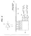
- Fig. 6 shows a model diagram of the encoder. According to the encoder, a
detector 703 detects light emitted from anLED 701 through acode wheel 702 and generates a signal. Light transmittingportions 704 and lightnon-transmitting portions 705 are arranged on thecode wheel 702 at predetermined intervals.Photodiodes detector 703 at predetermined intervals. The lights detected by thephotodiodes electric signal A 710, an electric signal *A 711, anelectric signal B 712, and an electric signal *B 713 and output them. The outputtedelectric signals Channel B 717, bycomparators - Fig. 7 shows waveforms of the differential output signals. A signal which is inverted at a cross point of an
electric signal A 801 and an electric signal *A 802 becomes aChannel A 803. When a velocity is constant, a duty ratio of the Channel A 803 is ideally equal to 50%. However, the duty ratio changes due to various factors. Serous one of the factors is a sensitivity difference of the photodiodes. - Fig. 8 shows waveforms of the differential output signals in the case where there is a difference between the sensitivities of the photodiodes. The sensitivity of the photodiode appears as an amplitude difference of the electric signals. Fig. 8 shows a
Channel A 903 in the case where an amplitude of anelectric signal A 901 is smaller than that of an electric signal *A 902. It will be understood from Fig. 8 that the sensitivity difference of the photodiodes changes a duty ratio of an output signal. However, it does not exert an influence on a period of the Channel A. Because of the reasons as mentioned above, generally, the period of the output signal of the encoder has the highest precision. - Position data and velocity data are obtained as control data of the DC motor from the encoder signal. To obtain more accurate data as velocity data, generally, a one-edge sampling system for counting and employing, for example, a period in a range from a rising-up edge to another rising-up edge of an output signal is used.
- However, when the velocity data is obtained by the one-edge sampling system, the velocity data is not updated unless the output signal of the encoder elapses one period. That is, the number of times of update of the velocity data is only 1/2 as compared to that of a both-edge sampling system and is only 1/4 as compared to that in case of sampling both edges of two phases, i.e. the Channel A and the Channel B.
- For example, when considering a paper feed control of the ink jet recording apparatus, the paper is fed at a high speed at the beginning and a servo control is performed at a low speed from a position that is slightly before a stop position. After that, the control mode is shifted to a stop mode at a position just before a target stop position, thereby stopping the paper at the target position. In this case, the operation for stabilizing the low-speed servo control at the position which is slightly before the stop position, largely influences on a stop precision of the paper.
- As mentioned above, when the paper is fed at a low speed, a change in encoder signal naturally becomes slow and an updating interval of the velocity data in the one-edge sampling system also becomes long. Therefore, a case where the velocity data obtained at a servo period is not updated from previously obtained velocity data occurs, and thus a problem such that the servo operation is not stable occurs.
- If the both-edge sampling system or the like is used in order to solve the above problem, although the updating interval of the velocity data becomes short, the precision of the velocity data deteriorates due to the above-mentioned reasons, and thus a problem such that the servo operation is not stable similarly occurs.
- It is a concern of the invention to provide a digital encoder controllmethod and apparatus which can realise the stable servo operation of a short velocity data updating interval at a precision that is equal to that of a conventional one-edge sampling system. Aspects of the invention are set out in
claims -
- Fig. 1 is a whole perspective view showing a schematic structure of a serial type ink jet printer as an embodiment of the invention;
- Fig. 2 is a block diagram for explaining the first embodiment of the invention;
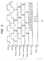
- Fig. 3 is a timing chart for explaining the first embodiment of the invention;
- Fig. 4 is a block diagram for explaining the second embodiment of the invention;
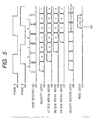
- Fig. 5 is a timing chart for explaining the second embodiment of the invention;
- Fig. 6 is a model diagram of a digital encoder;
- Fig. 7 is a diagram of waveforms of encoder differential outputs; and
- Fig. 8 is a diagram of waveforms of encoder differential outputs in the case where there is a sensitivity difference between photodiodes.
-
- A preferred embodiment of the invention will now be described in detail hereinbelow with reference to the drawings. An example of a serial type ink jet printer in which a recording head having a detachable ink tank has been mounted will be described here.
- Fig. 1 is a whole perspective view showing a schematic structure of the serial type ink jet printer in the first embodiment of the invention. In the diagram,
reference numeral 1 denotes a recording head having an ink tank and 2 indicates a carriage on which therecording head 1 is mounted. - A
guide shaft 3 is inserted into a bearing portion of thecarriage 2 in a state where it is slidable in the main scanning direction. Both edges of theshaft 3 are fixed to achassis 14. A driving force of a drivingmotor 5 is transferred to thecarriage 2 through abelt 4 as carriage drive transfer means which is in engagement with thecarriage 2, so that thecarriage 2 moves in the main scanning direction. - In a recording standby mode, recording
papers 15 are stacked onto a paper feed base 6. At the start of the recording, the recording papers are fed one by one by a paper feed roller (not shown). To convey the fed recording paper, a conveyingroller 10 is rotated by a driving force of a conveyingmotor 7 as a DC motor through a gear train (motor gear 8, conveying roller gear 9) as transfer means. Therecording paper 15 is conveyed only by a proper feed amount by the conveyingroller 10 andpinch rollers 11 which are rotated with being pressed onto theconveying roller 10 by a pinch roller spring (not shown). - Slits of a code wheel (rotary encoder film 16) inserted into the
conveying roller gear 9 with a pressure are detected and counted by anencoder sensor 17, whereby a conveying amount is managed, and thus a feed amount may be controlled at a high precision. - Fig. 2 shows a block diagram for explaining the first embodiment of the invention. In Fig. 2, by the driving of a
motor 115, anencoder 101 outputs two signals of phase A and phase B to an encodersignal control unit 102. Anedge detecting unit 103 for detecting edges of the encoder signals is provided in the encodersignal control unit 102. In theedge detecting unit 103, each edge of each phase is detected, that is, a rising-upedge detection 104 of phase A, a falling-down edge detection 105 of phase A, a rising-upedge detection 106 of phase B, and a falling-down edge detection 107 of phase B are independently performed, so that a signal synchronized with each edge is generated. - The signals synchronized with the respective edges are sent to edge interval counters 108, 109, 110, and 111, respectively. Each edge interval is independently counted. The edge detection signals are sent from the
edge detecting unit 103 to the edge interval counters 108, 109, 110, and 111 and each time the edge interval is determined, the velocity data in a velocitydata storing unit 112 is overwritten. When a servo period of a predetermined interval comes, aservo controller 113 reads (Read) the velocitydata storing unit 112 in order to obtain the velocity data necessary for the servo control. On the basis of the obtained velocity data, position data, and the like, theservo controller 113 executes an arithmetic operation and outputs optimum motor control data to amotor driver 114. Themotor driver 114 outputs a driving signal to themotor 115 in accordance with the inputted control data, thereby driving themotor 115. - Fig. 3 shows a timing chart for explaining the first embodiment of the invention. With respect to
phase A 301 andphase B 302 of the encoder signal, the following edge detection signals are generated: that is, a phase A rising-upedge detection signal 303 synchronized with a rising-up edge ofphase A 301; a phase B rising-upedge detection signal 304 synchronized with a rising-up edge ofphase B 302; a phase A falling-downedge detection signal 305 synchronized with a falling-down edge ofphase A 301; and a phase B falling-downedge detection signal 306 synchronized with a falling-down edge ofphase B 302, respectively. An interval of each edge signal is independently counted by each counter (not shown). - If a rising-up edge interval (a) of phase A is determined due to the generation of the phase A rising-up
edge detection signal 303, the counter (not shown) which counts the phase A rising-up edge interval is reset and the determined phase A rising-up edge interval (a) is latched into avelocity data latch 307. Subsequently, if a rising-up edge interval (b) of phase B is determined due to the generation of the phase B rising-upedge detection signal 304, the counter (not shown) which counts the phase B rising-up edge interval is reset and the determined phase B rising-up edge interval (b) is overwritten into the velocity data latch 307. After that, if the phase A falling-downedge detection signal 305 is generated, the counter (not shown) which counts a phase A falling-down edge interval is reset, a falling-down edge interval (c) of phase A is overwritten into the velocity data latch 307. If the phase B falling-downedge detection signal 306 is generated, the counter (not shown) which counts a phase B falling-down edge interval is reset, and a falling-down edge interval (d) of phase B is overwritten into the velocity data latch 307. If the phase A rising-upedge detection signal 303 is generated again, the counter (not shown) which counts the phase A rising-up edge interval is reset, and a determined rising-up edge interval (e) of phase A is latched into the velocity data latch 307. The operation similar to that mentioned above is repeated after that. - When the servo controller requests the reading of the velocity data at a timing of a
servo period 308, velocity data (d) in the velocity data latch 307 is latched into aRead Latch 309. The servo controller reads the velocity data in theRead Latch 309. - As will be obviously understood from Fig. 3, according to the invention, the velocity data is updated four times for one period of time of the encoder and the velocity data certainly becomes the count data between the same edges. Thus, even if the servo control is performed at a low speed, the stable servo control can be performed.
- Fig. 4 shows a block diagram for explaining the second embodiment of the invention. By the driving of a
motor 211, anencoder 201 outputs two signals of phase A and phase B to an encodersignal control unit 202. Anedge detecting unit 203 for detecting edges of the encoder signal is provided in the encodersignal control unit 202. Theedge detecting unit 203 generates a signal synchronized with each edge each time each edge of each phase is detected, that is, each time a rising-up edge and a falling-down edge of phase A and a rising-up edge and a falling-down edge of phase B are detected. The signals synchronized with the edges are sent to an edgeinterval detecting unit 204 and edge intervals are counted. - When the edge detection signals are outputted from the
edge detecting unit 203 and the edge interval is determined, the velocity data latched so far in the edgeinterval detecting unit 204 is latched into a first edgeinterval history unit 205. Similarly, the velocity data latched in the first edgeinterval history unit 205 is latched into a second edgeinterval history unit 206. The velocity data latched in the second edgeinterval history unit 206 is latched into a third edgeinterval history unit 207. - Each velocity data latched in the edge
interval detecting unit 204, first edgeinterval history unit 205, second edgeinterval history unit 206, and third edgeinterval history unit 207 is sent to an edgeinterval adder unit 208. A result of addition of four velocity data is stored as velocity data at that time. That is, in the edgeinterval adder unit 208, the velocity data is updated each time the edge detection signals are outputted from theedge detecting unit 203. - A
servo controller 209 reads the velocity data in the edgeinterval adder unit 208 when the servo period of a predetermined interval comes. On the basis of the obtained velocity data, position data, and the like, theservo controller 209 executes an arithmetic operation and outputs the optimum motor control data to amotor driver 210. Themotor driver 210 outputs a driving signal to themotor 211 in accordance with the inputted control data, thereby driving themotor 211. - Although the addition of the velocity data is executed in the encoder
signal control unit 202, theservo controller 209 can also read the velocity data latched in each of the edgeinterval detecting unit 204, first edgeinterval history unit 205, second edgeinterval history unit 206, and third edgeinterval history unit 207 and add them in a software manner. - Fig. 5 shows a timing chart for explaining the second embodiment of the invention. With respect to
phase A 401 andphase B 402 of the encoder signal, each time each edge of each phase is detected, anedge detection signal 403 synchronized with each edge is generated. Intervals between the edge signals are counted by a counter (not shown). When the edge interval (a) is determined due to the generation of theedge detection signal 403, the counter (not shown) which counts the edge intervals is reset and the determined edge interval (a) is latched into avelocity data latch 404. When theedge detection signal 403 is generated again and the edge interval (b) is determined, the counter which counts the edge intervals is reset and the determined edge interval (b) is overwritten into the velocity data latch 404. The velocity data (a) is shifted to a firstedge interval history 405. - After that, when the
edge detection signal 403 is generated again, the counter is reset. The edge interval (c) is latched into the velocity data latch 404, the velocity data (b) is latched into the firstedge interval history 405, and the velocity data (a) is latched into a secondedge interval history 406, respectively. When theedge detection signal 403 is further generated, the counter is reset. The edge interval (d) is latched into the velocity data latch 404, the velocity data (c) is latched into the firstedge interval history 405, the velocity data (b) is latched into the secondedge interval history 406, and the velocity data (a) is latched into a thirdedge interval history 407, respectively. - In a manner similar to that mentioned above, each time the
edge detection signal 403 is generated, the latching operation is repeated. Each time theedge detection signal 403 is generated, a result of an addition of values in the velocity data latch 404, firstedge interval history 405, secondedge interval history 406, and thirdedge interval history 407 is stored into avelocity addition latch 408. - When the servo controller requests the reading of the velocity data at the timing of a
servo period 409, the data in thevelocity addition latch 408 is latched into aRead Latch 410. The servo controller reads the velocity data in theRead Latch 410. - As will be obviously understood from Fig. 5, according to the invention, the velocity data is updated four times for one period of time of the encoder. The velocity data certainly becomes count data between the same edges. Thus, even if the servo control is executed at a low speed, the stable servo control can be performed.
- As described above, according to the embodiment, when the velocity data is obtained from the output signal from the digital encoder, the velocity data updating interval is set to a short interval which is 1/2 or 1/4 time as large as that of the one-edge sampling system at a precision that is equivalent to that obtained in case of the one-edge sampling system. Particularly, the servo operation in case of performing the servo control at a low speed can be stabilized.
Claims (13)
- A digital encoder control method comprising the steps of:wherein each time the edges are detected by said edge detecting means, the period data between the same edges as the detected edges is outputted as control velocity data of said driving means.arranging driving means;arranging frequency signal generating means for generating a pulse signal of a frequency according to a driving velocity of a driven member which is driven by said driving means;arranging edge detecting means for detecting a rising-up edge and a falling-down edge of said pulse signal; andarranging period data detecting means for counting period data between edges detected by said edge detecting means,
- A method according to claim 1, further comprising the steps of:arranging period history data storing means for storing a one-preceding history of the period data counted by said period data detecting means;arranging adding means for adding said period data and said period history data each time said edge detecting means detects the edges; andoutputting the period data obtained by said adding means as said control velocity data of said driving means.
- A digital encoder control method comprising the steps of:arranging driving means;arranging frequency signal generating means for generating a pulse signal of a frequency according to a driving velocity of a driven member which is driven by said driving means;arranging edge detecting means for independently detecting a rising-up edge and a falling-down edge of said pulse signal;arranging period data detecting means of a period between rising-up edges for counting a period from a rising-up to another rising-up of the pulse signal detected by said edge detecting means; andarranging period data detecting means of a period between falling-down edges for counting a period from a falling-down to another falling-down of the pulse signal detected by said edge detecting means,wherein when the edge detected by said edge detecting means is the rising-up edge, the period data detected by said period data detecting means of the period between the rising-up edges is outputted as control velocity data of said driving means, andwhen the edge detected by said edge detecting means is the falling-down edge, the period data detected by said period data detecting means of the period between the falling-down edges is outputted as said control velocity data of said driving means.
- A digital encoder control method comprising the steps of:arranging driving means;arranging first frequency signal generating means for generating a first pulse signal of a frequency according to velocity data of a driven member which is driven by said driving means;arranging second frequency signal generating means for generating a second pulse signal whose phase is deviated by about 90° as an electric angle from said first pulse signal;arranging edge detecting means for independently detecting a rising-up edge and a falling-down edge of said first pulse signal and a rising-up edge and a falling-down edge of said second pulse signal;arranging first period data detecting means for counting period data from a rising-up to another rising-up of said first pulse signal;arranging second period data detecting means for counting period data from a falling-down to another falling-down of said first pulse signal;arranging third period data detecting means for counting period data from a rising-up to another rising-up of said second pulse signal; andarranging fourth period data detecting means for counting period data from a falling-down to another falling-down of said second pulse signal,wherein when the edge detected by said edge detecting means is the rising-up edge of said first pulse signal, the period data detected by said first period data detecting means is outputted as control velocity data of said driving means,when the edge detected by said edge detecting means is the falling-down edge of said first pulse signal, the period data detected by said second period data detecting means is outputted as said control velocity data of said driving means,when the edge detected by said edge detecting means is the rising-up edge of said second pulse signal, the period data detected by said third period data detecting means is outputted as said control velocity data of said driving means, andwhen the edge detected by said edge detecting means is the falling-down edge of said second pulse signal, the period data detected by said fourth period data detecting means is outputted as said control velocity data of said driving means.
- A digital encoder control method comprising the steps of:arranging driving means;arranging first frequency signal generating means for generating a first pulse signal of a frequency according to velocity data of a driven member which is driven by said driving means;arranging second frequency signal generating means for generating a second pulse signal whose phase is deviated by about 90° as an electric angle from said first pulse signal;arranging edge detecting means for independently detecting a rising-up edge and a falling-down edge of said first pulse signal and a rising-up edge and a falling-down edge of said second pulse signal;arranging period data detecting means for counting a period between the edges detected by said edge detecting means;arranging first period history data storing means for storing a one-preceding history of period data of said period counted by said period data detecting means;arranging second period history data storing means for storing a two-preceding history of period data of said period counted by said period data detecting means;arranging third period history data storing means for storing a three-preceding history of period data of said period counted by said period data detecting means;arranging adding means for adding said period data, said one-preceding history, said two-preceding history, and said three-preceding history each time said edge detecting means detects the edges; andoutputting the period data obtained by said adding means as said control velocity data of said driving means.
- A method according to any one of claims 1 to 5, wherein said driven member is a conveying roller for conveying a recording paper to which a recording is performed by a recording head.
- A digital encoder control apparatus comprising:wherein each time the edges detects said edge detecting means, the period data between the same edges as the detected edges is outputted as control velocity data to control said driving means.frequency signal generating means for generating a pulse signal of a frequency according to a driving velocity of a driven member which is driven by driving means;edge detecting means for detecting a rising edge and a falling edge of said pulse signal; andperiod data detecting means for counting period data between edges detected by said edge detecting means,
- Apparatus according to claim 7, further comprising:history data storing means for storing a preceding history of the period data counted by said period data detecting means;adding means for adding said period data and said period history data each time said edge detecting means detects the using and falling edges; andoutputting the period data obtained by said adding means as said control velocity data of said driving means.
- Apparatus according to claim 7 or claim 8 comprising:wherein said period data detecting means are adapted to detect periods between rising edges so as to count a period from one rising pulse to another of the pulse signal detected by said edge detecting means, and toperiods between falling edges so as to count a period from one falling pulse to another of the pulse signal detected by said edge detecting means, andwherein when the edge detected by said edge detecting means is a rising edge, the period data detected by said period data detecting means of the period between the rising edges is outputted as control velocity data for said driving means, andwhen the edge detected by said edge detecting means is a falling edge, the period data detected by said period data detecting means of the period between the falling edges is outputted as said control velocity data of said driving means.
- Apparatus according to claim 7 or claim 8 further comprising:wherein when an edge detected by said edge detecting means is a rising pulse of said first pulse signal, the period data detected by said first period data detecting means is outputted as control velocity data of said driving means,second frequency signal generating means for generating a second pulse signal whose phase is different from said first pulse signal; and wherein saidedge detecting means are adapted independently to detect a rising edge and a falling edge of said first pulse signal and a rising edge and a falling edge of said second pulse signal;said period data detecting means comprise first period data detecting means for counting period data from one rising pulse to another of said first pulse signal;second period data detecting means for counting period data from one fall pulse to another said first pulse signal;third period data detecting means for countting period data from one rising pulse to another of said second pulse signal; andfourth period data detecting means for counting period data from one fall pulse to another said second pulse signal,when the edge detected by said edge detecting means is a falling pulse of said first pulse signal, the period data detected by said second period data detecting means is outputted as said control velocity data of said driving means,when the edge detected by said edge detecting means is a rising pulse of said second pulse signal, the period data detected by said third period data detecting means is outputted as said control velocity data of said driving means, andwhen the edge detected by said edge detecting means is a falling pulse of said second pulse signal, the period data detected by said fourth period data detecting means is outputted as said control velocity data of said driving means.
- Apparatus according to claim 7 or claim 8 further comprising:second frequency signal generating means for generating a second pulse signal whose phase is different from said first pulse signal, and wherein saidedge detecting means are adapted independently to detect a rising pulse and a falling pulse of said first pulse signal and a rising pulse and a falling pulse of said second pulse signal; and whereinsaid period data detecting means are adapted to count the periods between the edges detected by said edge detecting means; and further comprisingfirst period history data storing means for storing the immediately previous history of period data of periods counted by said period data detecting means;second period history data storing means for storing the history of period data of said periods counted by said period data detecting means immediately previous to that of said first period history storing means;third period history data storing means for storing the history of period data of said period counted by said period data detecting means immediately previous to that of said second period data detecting means, and further comprising:adding means for adding the period stored by said first, second and third period history storing means each time said edge detecting means detects edges; andoutputting the period data obtained by said adding means as said control velocity data of said driving means.
- Apparatus according to either of claims 10 or 11, wherein said first and second pulse signals differ in phase by approximately 90°.
- Apparatus according to any one of claims 7 to 12, wherein said driven member is a conveying roller for conveying recording medium on which recording is performed by a recording head.
Applications Claiming Priority (2)
| Application Number | Priority Date | Filing Date | Title |
|---|---|---|---|
| JP2000218488A JP3501737B2 (en) | 2000-07-19 | 2000-07-19 | Encoder signal control circuit and control method of the circuit |
| JP2000218488 | 2000-07-19 |
Publications (2)
| Publication Number | Publication Date |
|---|---|
| EP1175011A1 true EP1175011A1 (en) | 2002-01-23 |
| EP1175011B1 EP1175011B1 (en) | 2006-05-10 |
Family
ID=18713423
Family Applications (1)
| Application Number | Title | Priority Date | Filing Date |
|---|---|---|---|
| EP01306141A Expired - Lifetime EP1175011B1 (en) | 2000-07-19 | 2001-07-17 | Digital encoder control method and apparatus |
Country Status (4)
| Country | Link |
|---|---|
| US (1) | US6515445B2 (en) |
| EP (1) | EP1175011B1 (en) |
| JP (1) | JP3501737B2 (en) |
| DE (1) | DE60119444T2 (en) |
Cited By (3)
| Publication number | Priority date | Publication date | Assignee | Title |
|---|---|---|---|---|
| EP1348655A3 (en) * | 2002-03-29 | 2004-12-22 | Brother Kogyo Kabushiki Kaisha | Sheet feeding apparatus |
| EP2037569A4 (en) * | 2006-06-07 | 2012-05-16 | Sharp Kk | Control device and control method |
| CN105738642A (en) * | 2016-02-03 | 2016-07-06 | 上海新源工业控制技术有限公司 | T-method motor speed measurement method of four-way parallel sampling |
Families Citing this family (12)
| Publication number | Priority date | Publication date | Assignee | Title |
|---|---|---|---|---|
| US6853161B2 (en) * | 2002-07-31 | 2005-02-08 | Canon Kabushiki Kaisha | Recording apparatus, motor control apparatus, and motor control method |
| US7036902B2 (en) * | 2002-08-22 | 2006-05-02 | Canon Kabushiki Kaisha | Printing apparatus |
| JP3809406B2 (en) * | 2002-08-29 | 2006-08-16 | キヤノン株式会社 | Recording apparatus and recording apparatus control method |
| JP4447891B2 (en) * | 2003-10-31 | 2010-04-07 | キヤノン株式会社 | DC motor control apparatus and recording apparatus |
| US6873129B1 (en) | 2003-12-16 | 2005-03-29 | Lexmark International Inc. | Method of controlling rotational velocity of a rotatable member during encoder initialization for an imaging apparatus |
| JP4788347B2 (en) * | 2006-01-11 | 2011-10-05 | セイコーエプソン株式会社 | Speed detection device and speed detection method |
| US7352293B1 (en) * | 2007-04-23 | 2008-04-01 | Hewlett-Packard Development Company, L.P. | Multi-mode encoder output generator |
| JP2010236965A (en) * | 2009-03-31 | 2010-10-21 | Hitachi Ltd | Speed detection device |
| JP5402985B2 (en) * | 2011-05-20 | 2014-01-29 | コニカミノルタ株式会社 | Image forming apparatus, image forming apparatus control method, and image forming apparatus control program |
| JP6126374B2 (en) | 2012-12-18 | 2017-05-10 | キヤノン株式会社 | Recording apparatus and recording control method |
| JP6757287B2 (en) * | 2017-04-11 | 2020-09-16 | 東洋電機製造株式会社 | Speed detector |
| CN115890923A (en) * | 2021-08-13 | 2023-04-04 | 广东博智林机器人有限公司 | Hole punching device and method for detecting hole punching obstacles |
Citations (4)
| Publication number | Priority date | Publication date | Assignee | Title |
|---|---|---|---|---|
| JPS63198814A (en) * | 1987-02-13 | 1988-08-17 | Ricoh Co Ltd | Speed, position, rotation direction detection method |
| EP0343352A1 (en) * | 1988-05-06 | 1989-11-29 | Heidelberger Druckmaschinen Aktiengesellschaft | Method and apparatus for the measurement of the rotational speed of a machine |
| EP0706896A2 (en) * | 1994-10-14 | 1996-04-17 | Xerox Corporation | Programmable encoder for carriage control |
| WO1999066335A1 (en) * | 1998-06-16 | 1999-12-23 | M.E.A. Motor Inspection Ltd. | Method and system for performance testing of rotating machines |
Family Cites Families (9)
| Publication number | Priority date | Publication date | Assignee | Title |
|---|---|---|---|---|
| US4158800A (en) * | 1976-10-26 | 1979-06-19 | Ncr Corporation | Control system |
| EP0477412A1 (en) * | 1990-09-27 | 1992-04-01 | Siemens Aktiengesellschaft | Process for filtering digital signals |
| JPH06295285A (en) * | 1993-02-15 | 1994-10-21 | Tokyo Electric Co Ltd | Interface device and printer using this device |
| JP3384667B2 (en) * | 1995-01-11 | 2003-03-10 | 株式会社リコー | Electronic equipment |
| JPH11277808A (en) * | 1998-03-26 | 1999-10-12 | Brother Ind Ltd | Timing pulse generator and printer |
| US6111384A (en) * | 1998-05-26 | 2000-08-29 | Eastman Kodak Company | Method for controlling motor speed |
| JP3848502B2 (en) * | 1998-08-28 | 2006-11-22 | 東芝テック株式会社 | Printer control device |
| JP3438612B2 (en) * | 1998-10-13 | 2003-08-18 | 富士ゼロックス株式会社 | Stepping motor control device |
| US6302514B1 (en) * | 1999-09-03 | 2001-10-16 | Lexmark International, Inc. | Method and apparatus for automatically correcting the fire timing of a printhead carrier due to linear encoder velocity errors |
-
2000
- 2000-07-19 JP JP2000218488A patent/JP3501737B2/en not_active Expired - Fee Related
-
2001
- 2001-07-17 US US09/905,876 patent/US6515445B2/en not_active Expired - Lifetime
- 2001-07-17 EP EP01306141A patent/EP1175011B1/en not_active Expired - Lifetime
- 2001-07-17 DE DE60119444T patent/DE60119444T2/en not_active Expired - Lifetime
Patent Citations (4)
| Publication number | Priority date | Publication date | Assignee | Title |
|---|---|---|---|---|
| JPS63198814A (en) * | 1987-02-13 | 1988-08-17 | Ricoh Co Ltd | Speed, position, rotation direction detection method |
| EP0343352A1 (en) * | 1988-05-06 | 1989-11-29 | Heidelberger Druckmaschinen Aktiengesellschaft | Method and apparatus for the measurement of the rotational speed of a machine |
| EP0706896A2 (en) * | 1994-10-14 | 1996-04-17 | Xerox Corporation | Programmable encoder for carriage control |
| WO1999066335A1 (en) * | 1998-06-16 | 1999-12-23 | M.E.A. Motor Inspection Ltd. | Method and system for performance testing of rotating machines |
Non-Patent Citations (1)
| Title |
|---|
| RULL ET AL: "Programmable logic design for an encoder-based velocity sensor in a DSP-controlled motion system", EMERGING TECHNOLOGIES AND FACTORY AUTOMATION, 1999. PROCEEDINGS. ETFA '99. 1999 7TH IEEE INTERNATIONAL CONFERENCE ON BARCELONA, SPAIN 18-21 OCT. 1999, PISCATAWAY, NJ, USA,IEEE, US, PAGE(S) 1243-1247, ISBN: 0-7803-5670-5, XP010365748 * |
Cited By (4)
| Publication number | Priority date | Publication date | Assignee | Title |
|---|---|---|---|---|
| EP1348655A3 (en) * | 2002-03-29 | 2004-12-22 | Brother Kogyo Kabushiki Kaisha | Sheet feeding apparatus |
| US7334787B2 (en) | 2002-03-29 | 2008-02-26 | Brother Kogyo Kabushiki Kaisha | Paper feeding apparatus |
| EP2037569A4 (en) * | 2006-06-07 | 2012-05-16 | Sharp Kk | Control device and control method |
| CN105738642A (en) * | 2016-02-03 | 2016-07-06 | 上海新源工业控制技术有限公司 | T-method motor speed measurement method of four-way parallel sampling |
Also Published As
| Publication number | Publication date |
|---|---|
| JP3501737B2 (en) | 2004-03-02 |
| US20020021232A1 (en) | 2002-02-21 |
| JP2002034274A (en) | 2002-01-31 |
| DE60119444D1 (en) | 2006-06-14 |
| EP1175011B1 (en) | 2006-05-10 |
| US6515445B2 (en) | 2003-02-04 |
| DE60119444T2 (en) | 2006-11-02 |
Similar Documents
| Publication | Publication Date | Title |
|---|---|---|
| US6515445B2 (en) | Digital encoder control method | |
| EP1602504A2 (en) | Motor control device and motor control method | |
| WO1988000530A1 (en) | Precision paper transport system | |
| US20060193672A1 (en) | Printer and paper feed controller | |
| WO2003076190A1 (en) | Printer, printing method, program, storage medium and computer system | |
| JP3859115B2 (en) | Printer motor control apparatus, control method, and recording medium recording control program | |
| US6729613B2 (en) | Method for operating sheet pick and feed systems for printing | |
| US7176649B2 (en) | DC motor control apparatus and recording apparatus | |
| WO2004091917A1 (en) | Device, system, and method for discharging liquid | |
| US7810901B2 (en) | Driving apparatus | |
| EP1201445A2 (en) | Recording apparatus | |
| US7784892B2 (en) | Printer and method of controlling the same | |
| JP4760090B2 (en) | Conveying apparatus and image forming apparatus | |
| JP4868859B2 (en) | Position detection apparatus, position detection method, and image forming apparatus | |
| US7549813B2 (en) | Printer, printing method, program, computer system | |
| KR100709365B1 (en) | Position control device, and scanner and image forming device having same | |
| US20040090127A1 (en) | Motor controller for image reading apparatus, and image reading apparatus with the same | |
| JP2011096091A (en) | Movement detection apparatus and recording apparatus | |
| JPS62238780A (en) | Printer | |
| JP2006150619A (en) | Printing apparatus, computer program, printing system, and printing method | |
| JP2007210747A (en) | Edge detector, printer, edge detection method and print control method | |
| JP2005074750A (en) | Recording apparatus | |
| JP2006224559A (en) | Ink jet printer | |
| US10870292B2 (en) | Indexing a media feed shaft | |
| US8890445B2 (en) | Drive control device and drive control method |
Legal Events
| Date | Code | Title | Description |
|---|---|---|---|
| PUAI | Public reference made under article 153(3) epc to a published international application that has entered the european phase |
Free format text: ORIGINAL CODE: 0009012 |
|
| AK | Designated contracting states |
Kind code of ref document: A1 Designated state(s): AT BE CH CY DE DK ES FI FR GB GR IE IT LI LU MC NL PT SE TR Kind code of ref document: A1 Designated state(s): DE ES FR GB IT NL |
|
| AX | Request for extension of the european patent |
Free format text: AL;LT;LV;MK;RO;SI |
|
| 17P | Request for examination filed |
Effective date: 20020628 |
|
| AKX | Designation fees paid |
Free format text: DE ES FR GB IT NL |
|
| 17Q | First examination report despatched |
Effective date: 20020828 |
|
| GRAP | Despatch of communication of intention to grant a patent |
Free format text: ORIGINAL CODE: EPIDOSNIGR1 |
|
| GRAS | Grant fee paid |
Free format text: ORIGINAL CODE: EPIDOSNIGR3 |
|
| GRAA | (expected) grant |
Free format text: ORIGINAL CODE: 0009210 |
|
| AK | Designated contracting states |
Kind code of ref document: B1 Designated state(s): DE ES FR GB IT NL |
|
| PG25 | Lapsed in a contracting state [announced via postgrant information from national office to epo] |
Ref country code: NL Free format text: LAPSE BECAUSE OF FAILURE TO SUBMIT A TRANSLATION OF THE DESCRIPTION OR TO PAY THE FEE WITHIN THE PRESCRIBED TIME-LIMIT Effective date: 20060510 |
|
| REG | Reference to a national code |
Ref country code: GB Ref legal event code: FG4D |
|
| REF | Corresponds to: |
Ref document number: 60119444 Country of ref document: DE Date of ref document: 20060614 Kind code of ref document: P |
|
| PG25 | Lapsed in a contracting state [announced via postgrant information from national office to epo] |
Ref country code: ES Free format text: LAPSE BECAUSE OF FAILURE TO SUBMIT A TRANSLATION OF THE DESCRIPTION OR TO PAY THE FEE WITHIN THE PRESCRIBED TIME-LIMIT Effective date: 20060821 |
|
| NLV1 | Nl: lapsed or annulled due to failure to fulfill the requirements of art. 29p and 29m of the patents act | ||
| ET | Fr: translation filed | ||
| PLBE | No opposition filed within time limit |
Free format text: ORIGINAL CODE: 0009261 |
|
| STAA | Information on the status of an ep patent application or granted ep patent |
Free format text: STATUS: NO OPPOSITION FILED WITHIN TIME LIMIT |
|
| 26N | No opposition filed |
Effective date: 20070213 |
|
| PGFP | Annual fee paid to national office [announced via postgrant information from national office to epo] |
Ref country code: FR Payment date: 20090722 Year of fee payment: 9 |
|
| PGFP | Annual fee paid to national office [announced via postgrant information from national office to epo] |
Ref country code: IT Payment date: 20090717 Year of fee payment: 9 |
|
| REG | Reference to a national code |
Ref country code: FR Ref legal event code: ST Effective date: 20110331 |
|
| PG25 | Lapsed in a contracting state [announced via postgrant information from national office to epo] |
Ref country code: IT Free format text: LAPSE BECAUSE OF NON-PAYMENT OF DUE FEES Effective date: 20100717 Ref country code: FR Free format text: LAPSE BECAUSE OF NON-PAYMENT OF DUE FEES Effective date: 20100802 |
|
| PGFP | Annual fee paid to national office [announced via postgrant information from national office to epo] |
Ref country code: GB Payment date: 20170726 Year of fee payment: 17 Ref country code: DE Payment date: 20170731 Year of fee payment: 17 |
|
| REG | Reference to a national code |
Ref country code: DE Ref legal event code: R119 Ref document number: 60119444 Country of ref document: DE |
|
| GBPC | Gb: european patent ceased through non-payment of renewal fee |
Effective date: 20180717 |
|
| PG25 | Lapsed in a contracting state [announced via postgrant information from national office to epo] |
Ref country code: DE Free format text: LAPSE BECAUSE OF NON-PAYMENT OF DUE FEES Effective date: 20190201 Ref country code: GB Free format text: LAPSE BECAUSE OF NON-PAYMENT OF DUE FEES Effective date: 20180717 |