EP1174934A2 - Method of producing negative electrode for lithium secondary cell - Google Patents
Method of producing negative electrode for lithium secondary cell Download PDFInfo
- Publication number
- EP1174934A2 EP1174934A2 EP01306240A EP01306240A EP1174934A2 EP 1174934 A2 EP1174934 A2 EP 1174934A2 EP 01306240 A EP01306240 A EP 01306240A EP 01306240 A EP01306240 A EP 01306240A EP 1174934 A2 EP1174934 A2 EP 1174934A2
- Authority
- EP
- European Patent Office
- Prior art keywords
- thin film
- lithium
- base material
- source material
- air
- Prior art date
- Legal status (The legal status is an assumption and is not a legal conclusion. Google has not performed a legal analysis and makes no representation as to the accuracy of the status listed.)
- Granted
Links
Images

Classifications
-
- H—ELECTRICITY
- H01—ELECTRIC ELEMENTS
- H01M—PROCESSES OR MEANS, e.g. BATTERIES, FOR THE DIRECT CONVERSION OF CHEMICAL ENERGY INTO ELECTRICAL ENERGY
- H01M4/00—Electrodes
- H01M4/02—Electrodes composed of, or comprising, active material
- H01M4/13—Electrodes for accumulators with non-aqueous electrolyte, e.g. for lithium-accumulators; Processes of manufacture thereof
- H01M4/139—Processes of manufacture
- H01M4/1395—Processes of manufacture of electrodes based on metals, Si or alloys
-
- H—ELECTRICITY
- H01—ELECTRIC ELEMENTS
- H01M—PROCESSES OR MEANS, e.g. BATTERIES, FOR THE DIRECT CONVERSION OF CHEMICAL ENERGY INTO ELECTRICAL ENERGY
- H01M10/00—Secondary cells; Manufacture thereof
- H01M10/05—Accumulators with non-aqueous electrolyte
- H01M10/056—Accumulators with non-aqueous electrolyte characterised by the materials used as electrolytes, e.g. mixed inorganic/organic electrolytes
- H01M10/0561—Accumulators with non-aqueous electrolyte characterised by the materials used as electrolytes, e.g. mixed inorganic/organic electrolytes the electrolyte being constituted of inorganic materials only
- H01M10/0562—Solid materials
-
- H—ELECTRICITY
- H01—ELECTRIC ELEMENTS
- H01M—PROCESSES OR MEANS, e.g. BATTERIES, FOR THE DIRECT CONVERSION OF CHEMICAL ENERGY INTO ELECTRICAL ENERGY
- H01M10/00—Secondary cells; Manufacture thereof
- H01M10/05—Accumulators with non-aqueous electrolyte
- H01M10/052—Li-accumulators
-
- H—ELECTRICITY
- H01—ELECTRIC ELEMENTS
- H01M—PROCESSES OR MEANS, e.g. BATTERIES, FOR THE DIRECT CONVERSION OF CHEMICAL ENERGY INTO ELECTRICAL ENERGY
- H01M10/00—Secondary cells; Manufacture thereof
- H01M10/05—Accumulators with non-aqueous electrolyte
- H01M10/052—Li-accumulators
- H01M10/0525—Rocking-chair batteries, i.e. batteries with lithium insertion or intercalation in both electrodes; Lithium-ion batteries
-
- H—ELECTRICITY
- H01—ELECTRIC ELEMENTS
- H01M—PROCESSES OR MEANS, e.g. BATTERIES, FOR THE DIRECT CONVERSION OF CHEMICAL ENERGY INTO ELECTRICAL ENERGY
- H01M4/00—Electrodes
- H01M4/02—Electrodes composed of, or comprising, active material
- H01M4/04—Processes of manufacture in general
- H01M4/0402—Methods of deposition of the material
- H01M4/0421—Methods of deposition of the material involving vapour deposition
-
- H—ELECTRICITY
- H01—ELECTRIC ELEMENTS
- H01M—PROCESSES OR MEANS, e.g. BATTERIES, FOR THE DIRECT CONVERSION OF CHEMICAL ENERGY INTO ELECTRICAL ENERGY
- H01M4/00—Electrodes
- H01M4/02—Electrodes composed of, or comprising, active material
- H01M4/13—Electrodes for accumulators with non-aqueous electrolyte, e.g. for lithium-accumulators; Processes of manufacture thereof
- H01M4/134—Electrodes based on metals, Si or alloys
-
- H—ELECTRICITY
- H01—ELECTRIC ELEMENTS
- H01M—PROCESSES OR MEANS, e.g. BATTERIES, FOR THE DIRECT CONVERSION OF CHEMICAL ENERGY INTO ELECTRICAL ENERGY
- H01M4/00—Electrodes
- H01M4/02—Electrodes composed of, or comprising, active material
- H01M2004/021—Physical characteristics, e.g. porosity, surface area
-
- H—ELECTRICITY
- H01—ELECTRIC ELEMENTS
- H01M—PROCESSES OR MEANS, e.g. BATTERIES, FOR THE DIRECT CONVERSION OF CHEMICAL ENERGY INTO ELECTRICAL ENERGY
- H01M4/00—Electrodes
- H01M4/02—Electrodes composed of, or comprising, active material
- H01M2004/026—Electrodes composed of, or comprising, active material characterised by the polarity
- H01M2004/027—Negative electrodes
-
- H—ELECTRICITY
- H01—ELECTRIC ELEMENTS
- H01M—PROCESSES OR MEANS, e.g. BATTERIES, FOR THE DIRECT CONVERSION OF CHEMICAL ENERGY INTO ELECTRICAL ENERGY
- H01M2300/00—Electrolytes
- H01M2300/0017—Non-aqueous electrolytes
- H01M2300/0065—Solid electrolytes
- H01M2300/0068—Solid electrolytes inorganic
-
- Y—GENERAL TAGGING OF NEW TECHNOLOGICAL DEVELOPMENTS; GENERAL TAGGING OF CROSS-SECTIONAL TECHNOLOGIES SPANNING OVER SEVERAL SECTIONS OF THE IPC; TECHNICAL SUBJECTS COVERED BY FORMER USPC CROSS-REFERENCE ART COLLECTIONS [XRACs] AND DIGESTS
- Y02—TECHNOLOGIES OR APPLICATIONS FOR MITIGATION OR ADAPTATION AGAINST CLIMATE CHANGE
- Y02E—REDUCTION OF GREENHOUSE GAS [GHG] EMISSIONS, RELATED TO ENERGY GENERATION, TRANSMISSION OR DISTRIBUTION
- Y02E60/00—Enabling technologies; Technologies with a potential or indirect contribution to GHG emissions mitigation
- Y02E60/10—Energy storage using batteries
-
- Y—GENERAL TAGGING OF NEW TECHNOLOGICAL DEVELOPMENTS; GENERAL TAGGING OF CROSS-SECTIONAL TECHNOLOGIES SPANNING OVER SEVERAL SECTIONS OF THE IPC; TECHNICAL SUBJECTS COVERED BY FORMER USPC CROSS-REFERENCE ART COLLECTIONS [XRACs] AND DIGESTS
- Y10—TECHNICAL SUBJECTS COVERED BY FORMER USPC
- Y10T—TECHNICAL SUBJECTS COVERED BY FORMER US CLASSIFICATION
- Y10T29/00—Metal working
- Y10T29/49—Method of mechanical manufacture
- Y10T29/49002—Electrical device making
- Y10T29/49108—Electric battery cell making
-
- Y—GENERAL TAGGING OF NEW TECHNOLOGICAL DEVELOPMENTS; GENERAL TAGGING OF CROSS-SECTIONAL TECHNOLOGIES SPANNING OVER SEVERAL SECTIONS OF THE IPC; TECHNICAL SUBJECTS COVERED BY FORMER USPC CROSS-REFERENCE ART COLLECTIONS [XRACs] AND DIGESTS
- Y10—TECHNICAL SUBJECTS COVERED BY FORMER USPC
- Y10T—TECHNICAL SUBJECTS COVERED BY FORMER US CLASSIFICATION
- Y10T29/00—Metal working
- Y10T29/49—Method of mechanical manufacture
- Y10T29/49002—Electrical device making
- Y10T29/49108—Electric battery cell making
- Y10T29/49115—Electric battery cell making including coating or impregnating
Definitions
- the present invention relates to a method of producing a negative electrode for use in a lithium secondary cell.
- Japanese Patent Laying-Open No. 62-44960 discloses a method for manufacturing such a solid cell. The method includes successively forming a thin film of titanium disulfide as a positive electrode, a thin film of Li 2 O-Al 2 O 3 as an electrolyte, and a thin film of Li as a negative electrode on a substrate placed in an ionized cluster beam evaporation system.
- Japanese Patent Publication No. 5-48582 discloses an electrolytic material for such a solid cell.
- Lithium secondary cells are characterized by having a high-energy output per unit area or per unit weight as compared with other cells. Lithium secondary cells have been developed for practical use as a power source in mobile communications equipment, notebook computers, electric vehicles and the like.
- the lithium metal, the thin film of the sulfide-based inorganic solid electrolyte, and the source materials therefor are highly reactive to water, so that they cause the problem of degradation when exposed to the air.
- the above-mentioned publications related to the solid cell do not suggest a technique for independently producing a lithium-containing negative electrode itself. The problem of the degradation described above must be resolved for the production of such a freestanding negative electrode containing lithium and the sulfide-based solid electrolyte.
- An object of the present invention is to provide a method of producing a negative electrode for a lithium secondary cell, in which lithium metal, a source material for a thin film of a sulfide-based inorganic solid electrolyte, and a negative electrode having the thin film of the inorganic solid electrolyte formed thereon can be prevented from being degraded by air.
- the present invention is directed to a method of producing a negative electrode for a lithium secondary cell having a thin film made of an inorganic solid electrolyte.
- the method includes using a negative electrode base material placed in a closed container and an inorganic solid electrolyte source material placed in a closed container.
- the negative electrode base material has a surface made of a material selected from the group consisting of lithium metal and lithium alloys.
- the negative electrode base material placed in the closed container and the inorganic solid electrolyte source material placed in the closed container are placed into a chamber space, which is substantially inactive to lithium and which is insulated from air and provided adjacent to an apparatus for forming a thin film. In the chamber space, the negative electrode base material and the source material are respectively taken out from the closed containers.
- the negative electrode base material and the source material taken out are transferred into the apparatus for forming a thin film without being exposed to the air.
- the materials are used, and a thin film made of an inorganic solid electrolyte is formed on the negative electrode base material.
- the negative electrode base material having the thin film formed thereon is then transferred without being exposed to the air into a chamber space, which is substantially inactive to lithium and which is insulated from the air and provided adjacent to the apparatus.
- the negative electrode base material having the thin film is placed into a closed container. The negative electrode having the thin film placed in the closed container can be taken out from the chamber into the air without being degraded.
- the negative electrode base material for use in the method may be prepared by forming a thin film made of a material selected from the group consisting of lithium metal and lithium alloys on a base material by vapor deposition.
- the thin film made of the material selected from the group consisting of lithium metal and lithium alloys preferably has a thickness of 20 ⁇ m or less.
- the thickness of the thin film is typically in the range of 0.1 ⁇ m to 20 ⁇ m, and preferably in the range of 1 ⁇ m to 10 ⁇ m.
- the present invention is directed to another method of producing a negative electrode for a lithium secondary cell having a thin film made of an inorganic solid electrolyte.
- the method includes using a first source material placed in a closed container and a second source material placed in a closed container.
- the first source material is selected from the group consisting of lithium metal and lithium alloys.
- the second source material is for use in forming the inorganic solid electrolyte.
- the first and second source materials respectively placed in the closed containers are placed into a chamber space, which is substantially inactive to lithium and which is insulated from air and provided adjacent to an apparatus for forming a thin film. In the chamber space, the first and second source materials are respectively taken out from the closed containers.
- the first and second source materials taken out are transferred into the apparatus without being exposed to the air.
- the first and second materials are used, and a first thin film made of the first source material and a second thin film made of the second source material are formed on a base material.
- the base material having the first and second thin films formed thereon is then transferred without being exposed to the air into a chamber space, which is substantially inactive to lithium and which is insulated from the air and provided adjacent to the apparatus.
- the base material having the first and second thin films is placed into a closed container.
- the negative electrode having the thin films placed in the closed container can be taken out from the chamber into the air without being degraded.
- the first thin film may be formed by a vapor deposition method.
- the first thin film preferably has a thickness of 20 ⁇ m or less.
- the thickness of the thin film formed is typically in the range of 0.1 ⁇ m to 20 ⁇ m, and preferably in the range of 1 ⁇ m to 10 ⁇ m.
- the present invention is directed to a further method of producing a negative electrode for a lithium secondary cell having a thin film made of an inorganic solid electrolyte.
- a first source material selected from the group consisting of lithium metal and lithium alloys is placed in a closed container, and the first source material placed in the container is placed into a chamber space, which is substantially inactive to lithium and which is insulated from air and provided adjacent to a first apparatus for forming a thin film.
- the first source material is taken out from the closed container.
- the first source material taken out is transferred into the first apparatus without being exposed to the air.
- the first source material is used, and a first thin film made of the first source material is formed on a base material.
- the base material having the first thin film formed thereon is transferred from the first apparatus without being exposed to the air into a chamber space, which is substantially inactive to lithium and which is insulated from the air and provided adjacent to the first apparatus.
- the base material having the first thin film formed thereon is placed into a closed container.
- the base material having the first thin film formed thereon and being placed in the closed container, and a second source material for forming an inorganic solid electrolyte and being placed in a closed container are placed into a chamber space, which is substantially inactive to lithium and which is insulated from the air and provided adjacent to a second apparatus for forming a thin film.
- the base material having the first thin film formed thereon and the second source material are respectively taken out from the closed containers. Then, the base material having the first thin film formed thereon and the second source material taken out are transferred into the second apparatus without being exposed to the air.
- the second apparatus the second source material is used, and a second thin film made of the second source material is formed on the first thin film.
- the base material having the first and second thin films formed thereon is transferred from the second apparatus without being exposed to the air into a chamber space, which is substantially inactive to lithium and which is insulated from the air and provided adjacent to the second apparatus.
- the base material is placed into a closed container.
- the first thin film may be formed by a vapor deposition method.
- the first thin film preferably has a thickness of 20 ⁇ m or less.
- the thickness of the thin film formed is typically in the range of 0.1 ⁇ m to 20 ⁇ m, and preferably in the range of 1 ⁇ m to 10 ⁇ m.
- the source materials, the base materials, and the base materials having the thin film can be handled without being exposed to air, so that a negative electrode for a lithium secondary cell can be prepared without being degraded by air.
- the chamber space and the apparatus are preferably filled with a gas selected from the group consisting of helium, nitrogen, neon, argon, krypton, a mixture gas of two or more from the foregoing, and dry air having a dew point of -50°C or below.
- the chamber space and the apparatus are also preferably filled with a gas selected from the group consisting of helium, nitrogen, neon, argon, krypton, a mixture gas of two or more from the foregoing, and dry air having a dew point of -50°C or below.
- the inorganic solid electrolytes may include sulfides, oxides, nitrides, and mixtures thereof such as oxynitrides and oxysulfides.
- the sulfides may include Li 2 S, a compound of Li 2 S and SiS 2 , a compound of Li 2 S and GeS 2 , and a compound of Li 2 S and Ga 2 S 3 .
- the oxynitrides may include Li 3 PO 4-x N 2x/3 , Li 4 SiO 4-x N 2x/3 , Li 4 GeO 4-x N 2x/3 (0 ⁇ x ⁇ 4), and Li 3 BO 3-x N 2x/3 (0 ⁇ x ⁇ 3).
- the thin film made of the inorganic solid electrolyte specifically contains components A to C as follows:
- the thin film made of the inorganic solid electrolyte may further contain at least one of oxygen and nitrogen.
- the content of element B is typically 0.1% to 30% by atomic percent.
- the content of element C is typically 20% to 60% by atomic percent.
- the content of one or both of oxygen and nitrogen is typically 0.1% to 10%.
- the thin film made of the inorganic solid electrolyte may be amorphous.
- the thin film made of the inorganic solid electrolyte preferably has an ionic conductance (conductivity) of at least 1 ⁇ 10 -4 S/cm at 25°C.
- the ionic conductance of the thin film of the inorganic solid electrolyte at 25°C may be typically in the range of 1 ⁇ 10 -4 S/cm to 2.5 ⁇ 10 -3 S/cm, and preferably in the range of 5 ⁇ 10 -4 S/cm to 2.5 ⁇ 10 -3 S/cm.
- the thin film of the inorganic solid electrolyte formed in the present invention may have an activation energy of 40 kJ/mol or below.
- the activation energy of the thin film of the inorganic solid electrolyte may be in the range of 30 kJ/mol to 40 kJ/mol.
- the thin film made of the inorganic solid electrolyte may be formed by a vapor deposition method, and typically, is formed by any one method selected from the group consisting of sputtering, vapor evaporation, laser ablation, and ion plating.
- the thin film made of lithium metal or a lithium alloy may also be formed by a vapor deposition method, and typically, is formed by any one method selected from the group consisting of sputtering, vapor evaporation, laser ablation, and ion plating.
- the negative electrode produced by the present invention may be used to form a lithium secondary cell together with other necessary components such as a separator of porous polymer, a positive electrode, and an organic solution of electrolytes.
- the thin film made of the organic solid electrolyte is formed on the base material having a surface made of lithium metal or a lithium alloy, or the thin film made of lithium metal or a lithium alloy is formed on the negative electrode base material and then the thin film made of the inorganic solid electrolyte is formed thereon.
- the additive elements of the lithium alloys may include In, Ti, Zn, Bi, and Sn.
- the base material having a surface made of lithium or a lithium alloy may be composed of a base material made of a metal or an alloy and a thin film made of lithium or a lithium alloy formed thereon.
- the base material may be composed of a metal material (typically a metal foil or leaf) of at least one selected from the group consisting of copper, nickel, aluminum, iron, niobium, titanium, tungsten, indium, molybdenum, magnesium, gold, silver, platinum, alloys of two or more metals from the foregoing, and stainless steel, and a thin film made of lithium or a lithium alloy formed on the metal material.
- the base material for use in the process may be composed of a metal oxide such as SnO 2 or an electrically conductive carbon such as graphite, and a thin film made of lithium or a lithium alloy formed thereon.
- the thin film made of lithium or a lithium alloy typically has a thickness of 0.1 ⁇ m to 20 ⁇ m, and preferably a thickness of 1 ⁇ m to 10 ⁇ m.
- a foil or leaf made of lithium or a lithium alloy may be used as the base material.
- the base material used in the present invention may have a thickness of 1 ⁇ m to 100 ⁇ m from the viewpoint of application to the lithium cell and may have a thickness of 1 ⁇ m to 20 ⁇ m to give a compact product.
- the negative electrode base material for use in depositing the thin lithium metal or lithium alloy film may be made of a metal, an alloy, a metal oxide such as SnO 2 , an electrically conductive carbon such as graphite, or the like.
- the metal and the alloy used for the base material may include at least one of copper, nickel, aluminum, iron, niobium, titanium, tungsten, indium, molybdenum, magnesium, gold, silver, platinum, or an alloy of two or more metals from the foregoing, or stainless steel.
- the negative electrode base material preferably has a thickness of not more than 100 ⁇ m in order to reduce the size of the lithium cell, and preferably has a thickness of not less than 1 ⁇ m in order to keep an enough strength of the base material. Therefore, the thickness of the negative electrode base material may be 1 ⁇ m to 100 ⁇ m, and may be 1 ⁇ m to 20 ⁇ m for compactness.
- the thin film made of the inorganic solid electrolyte may be formed on a heated base material by a vapor deposition method, or the thin film made of the inorganic solid electrolyte may be formed on a base material at room temperature or at a temperature below 40°C and then the thin film made of the inorganic solid electrolyte may be subjected to heat treatment.
- heat treatment allows the thin film to have a relatively high ionic conductance.
- a heater may be used for the heat treatment.
- the heater employed may be attached to a holder for holding the base material or may be a radiation heater. The heater heats the base material or the thin film formed on the base material.
- the heating may be effected through a temperature rise caused by plasma or the like during the film deposition.
- plasma or the like can heat the base material, so that the thin film can be formed on the base material having a increased temperature.
- the heat treatment can effectively be carried out at a temperature higher than room temperature (5°C to 35°C) or at a temperature of 40°C or higher.
- a temperature higher than room temperature such as a temperature of 40°C or higher, preferably 100°C or higher may be used as the base material temperature in the case that the thin film is heated through the heating of the base material, or as the temperature for the heat treatment of the formed thin film.
- the thin film of the inorganic solid electrolyte is generally amorphous, and specifically glassy.
- the heating temperature is preferably below the glass transition temperature of the thin film of the inorganic solid electrolyte. Based on this point, a temperature of 200°C or below is preferably used as the temperature of the substrate in the case that the thin film is heated through the heating of the substrate, or as the temperature for the heat treatment of the formed thin film.
- the heating temperature is preferably lower than 179°C which is the melting point of metal lithium.
- the heating temperature is preferably lower than a temperature at which the texture of the thin film of the inorganic solid electrolyte changes (for instance, the glass transition temperature of the thin film of the inorganic solid electrolyte) and lower than a temperature at which the structure of the base material can no longer be maintained (for instance, the melting point of the base material).
- the heating temperature is preferably 40°C to 200°C, and more preferably not lower than 100°C and lower than 179°C.
- the thin film of the inorganic solid electrolyte formed in the present invention typically has a thickness of 0.01 ⁇ m to 10 ⁇ m, and preferably a thickness of 0.1 ⁇ m to 2 ⁇ m.
- the degree of vacuum of the background in the vapor deposition method is preferably not higher than 1.33 ⁇ 10 -4 Pa (1 ⁇ 10 -6 Torr).
- a low vacuum degree may induce oxidation or degradation of the lithium by water.
- the atmosphere under which the thin film is formed by the vapor deposition method may comprise a gas inactive to lithium, such as helium, neon, argon, krypton, or a mixture gas of two or more from the foregoing.
- the purity of the gas constituting the atmosphere is preferably at least 99.99% so that no degradation of the lithium due to the water may occur when the thin film of the inorganic solid electrolyte is formed on lithium metal or a lithium alloy.
- Fig. 1 is a schematic diagram showing the entire formation of an apparatus used for the present invention.
- a thin film deposition system is denoted by a reference numeral 1, an inlet of the thin film deposition system by 2, an outlet of the thin film deposition system by 3, and chambers by 4 and 5.
- a copper foil or leaf having a size of 100 mm ⁇ 50 mm and a thickness of 10 ⁇ m was bonded to a lithium metal foil or leaf having the same size and a thickness of 50 ⁇ m to produce a negative electrode base material.
- a thin film of an inorganic solid electrolyte having a thickness of 1 ⁇ m was formed by the sputtering of a Li 2 S-SiS 2 -P 2 O 5 -based target at room temperature under an Ar gas atmosphere to produce a negative electrode.
- Fig. 1 shows the entire formation of the apparatus used for the production of the negative electrode.
- the negative electrode base material and the target contained in a closed container of glass, plastic or the like is introduced into a chamber 4 attached to an inlet 2 of a thin film deposition system 1, and then, air is evacuated from chamber 4.
- chamber 4 is filled with argon gas having a purity of 99.99%.
- Thin film deposition system 1 is also filled with argon gas of 99.99% purity.
- Gloves are attached to chamber 4 so that one may insert the hands into the gloves to perform operations within chamber 4.
- the closed container is opened in chamber 4, and the negative electrode base material having the lithium metal foil or leaf and the target are taken out.
- a door at inlet 2 of the thin film deposition system is opened, the negative electrode base material and the target are placed into thin film deposition system 1, and the door at inlet 2 is closed. In this manner, the negative electrode base material and the target are placed into thin film deposition system 1 without being exposed to air.
- thin film deposition system 1 the target is used and the thin film of the inorganic solid electrolyte is formed on the negative electrode base material by the sputtering to produce a negative electrode. Then, thin film deposition system 1 is filled with argon gas having a purity of 99.99%. Then, air is evacuated from a chamber 5 attached to an outlet 3 of thin film deposition system 1, and thereafter, chamber 5 is filled with argon gas of 99.99% purity. Like chamber 4, chamber 5 also has gloves so that one may insert the hands into the gloves to perform operations within chamber 5.
- a door at outlet 3 of the thin film deposition system is opened, the negative electrode having the thin film of the inorganic solid electrolyte is taken out from thin film deposition system 1 and is placed into chamber 5, and the door at outlet 3 is closed.
- a closed container of glass, plastic or the like was placed into chamber 5 in advance.
- the negative electrode having the thin film of the inorganic solid electrolyte is placed into the container and the container is closed, and the closed container is taken out into the air. In this manner, the negative electrode having the thin film of the inorganic solid electrolyte can be transferred from thin film deposition system 1 to another place without being exposed to the air.
- any one of helium, nitrogen, neon, argon, and krypton, or a mixture gas of two or more from the foregoing, or dry air having a dew point of -50°C or below can be used without a problem.
- the gases used in the respective chambers and the thin film deposition system may be the same or different as required.
- the apparatus as shown in Fig. 1 has both of inlet 2 and outlet 3 for the thin film deposition system.
- one passage may double as the inlet and the outlet, and one chamber may be provided though which the base member and the source material are introduced into the thin film deposition system and the negative electrode is taken out from the thin film deposition system.
- An X-ray diffraction analysis revealed that the formed thin film of the inorganic solid electrolyte was in an amorphous state.
- the ionic conductance of the thin film of the inorganic solid electrolyte was 3 ⁇ 10 -4 S/cm at 25°C.
- a composition analysis revealed that the thin film had a composition of Li (0.42) : Si (0.13) : S (0.44) : P (0.002) : O (0.008) by atomic ratio.
- EC ethylene carbonate
- PC propylene carbonate
- LiPF 6 LiPF 6 was dissolved in the solution.
- Polyacrylonitrile (PAN) was dissolved in the mixture solution in a high concentration.
- the solution was cooled to give a PAN preparation containing large amounts of EC and PC with LiPF 6 dissolved.
- LiCoO 2 particles as an active material and carbon particles for providing electron conductivity were added to the PAN preparation.
- the resulting mixture was applied in a thickness of 300 ⁇ m onto a 20 ⁇ m-thick aluminum foil or leaf (a collector member for a positive electrode) to produce a positive electrode.
- the negative electrode having the thin film of the solid electrolyte, a separator (porous polymer film) and the positive electrode were stacked and then placed into a stainless steel container to be sealed.
- An organic solution of an electrolyte containing 1 mole % LiPF 6 as the electrolytic salt in a mixture solution of ethylene carbonate and propylene carbonate was added dropwise to the container.
- a lithium secondary cell was prepared under an argon gas atmosphere having a dew point of -60°C or below.
- the prepared cell was examined for the charge and discharge characteristics. In the examination, the cell was charged at a voltage of 4.2 V and maintained a capacity of 0.5 Ah (ampere-hour) until a constant discharge at 100 mA allowed the voltage to drop to 3.5 V. The energy density of the cell was 490 Wh (watt-hour)/1 (liter). The cell also remained stable after one hundred cycles of charge and discharge under the same conditions.
- Example 1 Except that the thin film of the inorganic solid electrolyte was formed by vacuum evaporation, a negative electrode and a lithium secondary cell were produced and evaluated as in Example 1. The obtained results were the same as those in Example 1.
- Example 1 Except that the thin film of the inorganic solid electrolyte was formed by laser ablation, a negative electrode and a lithium secondary cell were produced and evaluated as in Example 1.
- the composition of the formed thin film was found to be Li (0.40) : Si (0.13) : S (0.46) : P (0.003) : O (0.007) by atomic ratio. Except for the composition, the obtained results were the same as those in Example 1.
- Example 1 Except that the thin film of the inorganic solid electrolyte was formed by ion plating, a negative electrode and a lithium secondary cell were produced and evaluated as in Example 1. The obtained results were the same as those in Example 1.
- a copper foil or leaf having a size of 100 mm ⁇ 50 mm and a thickness of 10 ⁇ m was placed in a thin film deposition system.
- a thin film of lithium metal having a thickness of 5 ⁇ m was formed by the sputtering of a lithium metal target, and thereon, a thin film of an inorganic solid electrolyte having a thickness of 1 ⁇ m was formed by the sputtering of a Li 2 S-SiS 2 -P 2 O 5 -based target.
- the sputtering was carried out at room temperature under an Ar gas atmosphere.
- the lithium metal target and the Li 2 S-SiS 2 -P 2 O 5 -based target were introduced into a thin film deposition system and the negative electrode having the thin films of lithium metal and the inorganic solid electrolyte were taken out.
- the apparatus as shown in Fig. 1 was used to produce a negative electrode.
- After the copper foil or leaf was placed into thin film deposition system 1, closed containers of glass, plastic or the like respectively containing the two targets were placed into chamber 4 attached to inlet 2 of thin film deposition system 1, and then, air was evacuated from chamber 4. Then, chamber 4 was filled with argon gas having a purity of 99.99%.
- Thin film deposition system 1 was also filled with argon gas of 99.99% purity.
- the closed containers were opened in chamber 4 and the two targets were respectively taken out from the closed containers. Then, a door at inlet 2 of the thin film deposition system was opened, the two targets were placed into thin film deposition system 1, and the door at inlet 2 was closed. In this manner, the two targets were placed into thin film deposition system 1 without being exposed to the air.
- thin film deposition system 1 a lithium metal thin film was formed on the copper foil or leaf by the sputtering of the lithium metal target, and thereon, a thin film of an inorganic solid electrolyte was formed by the sputtering of the Li 2 S-SiS 2 -P 2 O 5 -based target.
- the obtained negative electrode was examined as in the case of Example 1. The obtained results were the same as those in Example 1.
- Example 4 Except that the thin film of lithium metal and the thin film of the inorganic solid electrolyte were formed by vacuum evaporation, a negative electrode and a lithium secondary cell were produced and evaluated as in Example 4. The obtained results were the same as those in Example 1.
- Example 5 Except that the thin film of lithium metal and the thin film of the inorganic solid electrolyte were formed by laser ablation, a negative electrode and a lithium secondary were produced and evaluated as in Example 5. The obtained results were the same as those in Example 4.
- Example 1 Except that the thin film of the inorganic solid electrolyte was formed by ion plating, a negative electrode and a lithium secondary cell were produced and evaluated as in Example 1. The obtained results were the same as those in Example 1.
- Example 1 Except that Li 2 S-SiS 2 -Li 2 O-P 2 O 5 was used to form the thin film of the inorganic solid electrolyte, a negative electrode and a secondary cell were produced and evaluated as in Example 1.
- the composition of the thin film was Li (0.43) : Si (0.12) : S (0.44) : P (0.002) : O (0.008) by atomic ratio. Except for the composition, the obtained results were the same as those in Example 1.
- Example 9 Except that the thin film of the inorganic solid electrolyte was formed by vacuum evaporation, a negative electrode and a lithium secondary cell were produced and evaluated as in Example 9. The obtained results were the same as those in Example 9.
- Example 9 Except that the thin film of the inorganic solid electrolyte was formed by laser ablation, a negative electrode and a lithium secondary cell were produced and evaluated as in Example 9. As a result, the composition of the thin film was found to be Li (0.41) : Si (0.13) : S (0.45) : P (0.002) : O (0.008) by atomic ratio. Except for the composition, the obtained results were the same as those in Example 9.
- Example 9 Except that the thin film of the inorganic solid electrolyte was formed by ion plating, a negative electrode and a lithium secondary cell were produced and evaluated as in Example 9. The obtained results were the same as those in Example 9.
- Example 9 Except that Li 2 S-SiS 2 -Li 2 O-P 2 O 5 was used to form the thin film of the inorganic solid electrolyte and the thin film of lithium metal was formed by vacuum evaporation, a negative electrode and a lithium secondary cell were produced and evaluated as in Example 9. The obtained results were the same as those in Example 9.
- Example 13 Except that the thin film of the inorganic solid electrolyte was formed by vacuum evaporation, a negative electrode and a lithium secondary cell were produced and evaluated as in Example 13. The obtained results were the same as those in Example 9.
- Example 13 Except that the thin film of the inorganic solid electrolyte was formed by laser ablation, a negative electrode and a lithium secondary cell were produced and evaluated as in Example 13. The obtained results were the same as those in Example 11.
- Example 13 Except that the thin film of the inorganic solid electrolyte was formed by ion plating, a negative electrode and a lithium secondary cell were produced and evaluated as in Example 13. The obtained results were the same as those in Example 9.
- a lithium metal thin film having a thickness of 10 ⁇ m was formed on a copper foil or leaf having a size of 100 mm ⁇ 50 mm and a thickness of 10 ⁇ m by vacuum evaporation.
- a thin film of an inorganic solid electrolyte was formed to have a thickness of 1 ⁇ m.
- two lithium metal foils or leafs each having the same size as the copper foil or leaf and each having a thickness of 30 ⁇ m were bonded to each other. The bonded lithium foils or leafs were used in place of the copper foil or leaf.
- the thin film of the inorganic solid electrolyte could be formed in a similar manner on the bonded lithium metal foils or leafs.
- Example 1 As in the case of Example 1, the lithium metal target and the electrolyte target were placed into the thin film deposition system and the negative electrode having the lithium metal thin film and the thin film of the inorganic solid electrolyte were taken out.
- the apparatus as shown in Fig. 1 was used to produce the negative electrode.
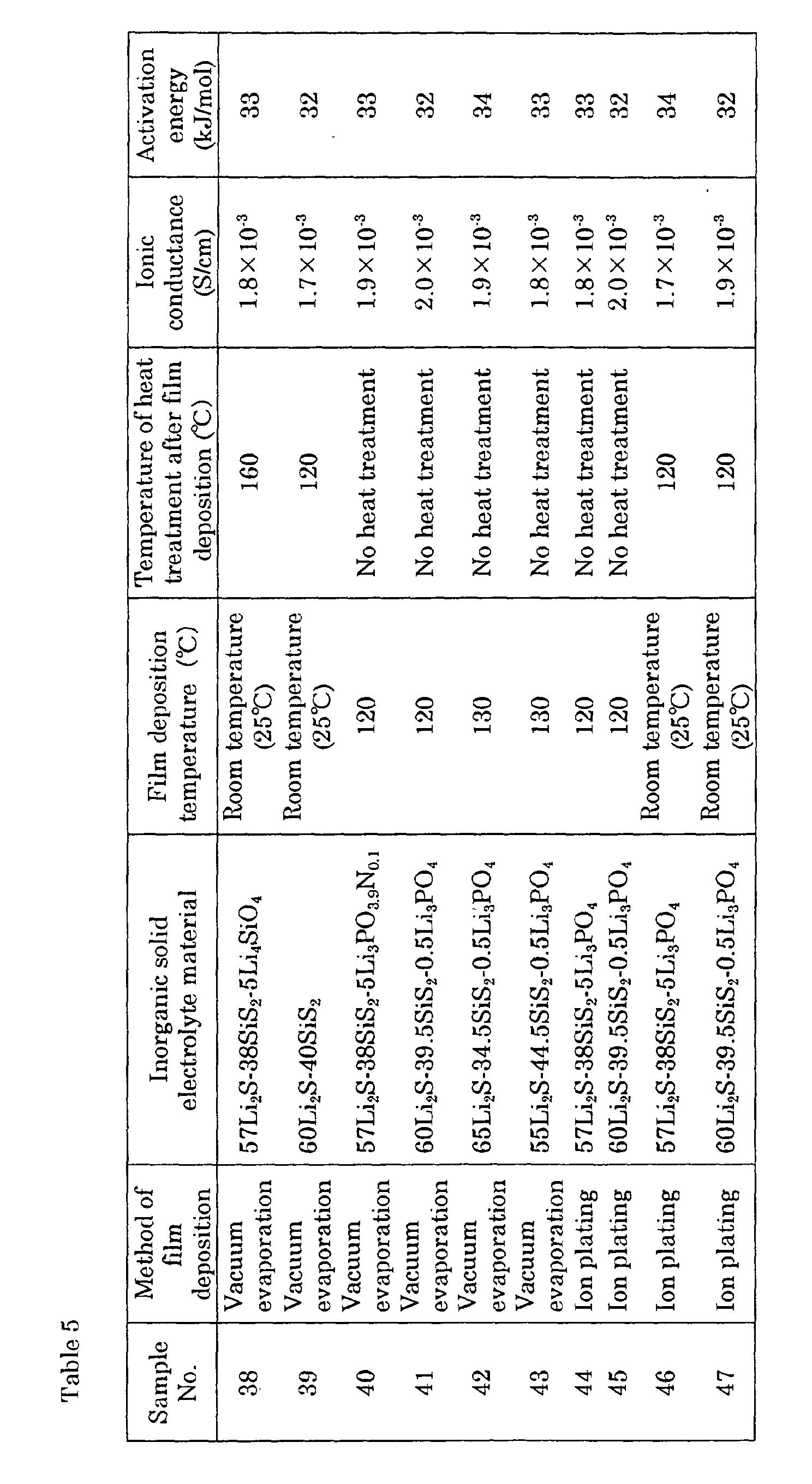
- the conditions as shown in Tables 1 to 5 were used to form thin films of inorganic solid electrolytes.
- Tables 1 to 5 also show the ionic conductance at 25°C of the thin films of the inorganic solid electrolytes, and the activation energy of the thin film of the inorganic solid electrolytes. The activation energy was obtained by the measurement of the temperature dependency of the ionic conductance at raised temperatures.
- Each base material having the thin film of lithium metal and the thin film of the inorganic solid electrolyte formed thereon was used as a negative electrode to produce a lithium secondary cell.
- Each negative electrode, a separator of porous polymer film, a positive electrode, an organic solution of electrolytes, and other conventionally required components were assembled into a lithium secondary cell. The outline of the process of the cell and the results of examining the cell are as follows.
- EC ethylene carbonate
- PC propylene carbonate
- LiPF 6 LiPF 6 was dissolved in the solution.
- Polyacrylonitrile (PAN) was dissolved in the mixture solution in a high concentration.
- the solution was cooled to give a PAN preparation containing large amounts of EC and PC with LiPF 6 dissolved.
- LiCoO 2 particles as an active material and carbon particles for providing electron conductivity were added to the PAN preparation.
- the resulting mixture was applied in a thickness of 300 ⁇ m onto a 20 ⁇ m-thick aluminum foil or leaf (a collector member for a positive electrode) to produce a positive electrode.
- Each negative electrode having the thin film of the solid electrolyte, a separator (porous polymer film), and the positive electrode were stacked and then placed into a stainless steel container.
- An organic solution of an electrolyte containing 1 mole % LiPF 6 as the electrolytic salt in a mixture solution EC and PC was added dropwise to the container.
- the stainless steel container was sealed under an argon gas atmosphere having a dew point of -60°C or below to give a lithium secondary cell.
- the prepared cells were examined for the charge and discharge characteristics. In the examination, each cell was charged at a voltage of 4.2 V and maintained a capacity of 0.5 Ah (ampere-hour) until a constant discharge at 100 mA allowed the voltage to drop to 3.5 V.
- the energy density of each cell was in the range of 500 to 550 Wh (watt-hour)/1 (liter). Each cell also remained stable after one hundred cycles of charge and discharge under the same conditions.
- the thin lithium metal film and the thin film of the inorganic solid electrolyte may be formed by the same method, or by different methods. In the latter case, an apparatus available for two or more kinds of thin film deposition methods may be used, and for example, the thin lithium metal film may be formed by vacuum evaporation and the thin film of the inorganic solid electrolyte by sputtering.
- the thin lithium metal film and the thin film of the inorganic solid electrolyte were formed in the same apparatus.
- the thin lithium metal film may only be formed, and then, the thin film of the inorganic solid electrolyte may be formed on the lithium film by a similar process in another apparatus.
- the following process may be employed.
- the thin lithium metal film is formed on the base member by a process similar to that in the Examples, and the product may be placed into a closed container without being exposed to the air.
- the base member having the thin lithium metal film is taken out from the closed container into another apparatus without being exposed to the air.
- the thin film of the inorganic solid electrolyte is formed in the different apparatus.
- the obtained negative electrode is placed into a closed container without being exposed to the air.
- lithium alloys may be used instead of the lithium metal.
- the additive elements that can constitute the lithium alloys may include In, Ti, Zn, Bi, and Sn.
- the lithium alloys may be deposited on the base material by a common vapor deposition method such as sputtering, vacuum evaporation, or laser ablation.
- the negative electrode produced according to the present invention can offer the lithium secondary cell a high energy density, excellent charge and discharge cycle characteristics, and high stability.
Landscapes
- Chemical & Material Sciences (AREA)
- Engineering & Computer Science (AREA)
- Chemical Kinetics & Catalysis (AREA)
- Electrochemistry (AREA)
- General Chemical & Material Sciences (AREA)
- Manufacturing & Machinery (AREA)
- Materials Engineering (AREA)
- Physics & Mathematics (AREA)
- Condensed Matter Physics & Semiconductors (AREA)
- General Physics & Mathematics (AREA)
- Inorganic Chemistry (AREA)
- Battery Electrode And Active Subsutance (AREA)
- Secondary Cells (AREA)
Abstract
Description
Then, the negative electrode base material and the source material taken out are transferred into the apparatus for forming a thin film without being exposed to the air. In the apparatus, the materials are used, and a thin film made of an inorganic solid electrolyte is formed on the negative electrode base material. The negative electrode base material having the thin film formed thereon is then transferred without being exposed to the air into a chamber space, which is substantially inactive to lithium and which is insulated from the air and provided adjacent to the apparatus. In the chamber space, the negative electrode base material having the thin film is placed into a closed container. The negative electrode having the thin film placed in the closed container can be taken out from the chamber into the air without being degraded.
Li3PO4-xN2x/3, Li4SiO4-xN2x/3, Li4GeO4-xN2x/3 (0<x<4), and Li3BO3-xN2x/3 (0<x<3).
Then, air is evacuated from a


Claims (16)
- A method of producing a negative electrode for a lithium secondary cell having a thin film made of an inorganic solid electrolyte, comprising the steps of:placing, a closed container containing a negative electrode base material and a closed container containing a source material for an inorganic solid electrolyte, into a chamber space (4), which is substantially inactive to lithium and which is insulated from air and provided adjacent to an apparatus (1) for forming said thin film, said base material having a surface made of a material selected from the group consisting of lithium metal and lithium alloys;taking out said base material and said source material from each container in said chamber space (4);transferring said base material and said source material into said apparatus (1) without exposing them to air;using said source material and forming a thin film made of an inorganic solid electrolyte on said base material in said apparatus (1);transferring said base material having said thin film formed thereon,without exposing it to air, from said apparatus (1) into a chamber space (5), which is substantially inactive to lithium and which is insulated from air and provided adjacent to said apparatus (1); andplacing said base material into a closed container in said chamber space (5).
- The method according to claim 1, wherein said negative electrode base material is prepared through the process of forming a thin film made of a material selected from the group consisting of lithium metal and lithium alloys on a base material by a vapor deposition method.
- The method according to claim 2, wherein said thin film made of a material selected from the group consisting of lithium metal and lithium alloys has a thickness of at most 20 µm.
- A method of producing a negative electrode for a lithium secondary cell having a thin film made of an inorganic solid electrolyte, comprising the steps of:placing, a closed container containing a first source material and a closed container containing a second source material, into a chamber space (4), which is substantially inactive to lithium and which is insulated from air and provided adjacent to an apparatus (1) for forming said thin film, said first source material being selected from the group consisting of lithium metal and lithium alloys, and said second source material being for use in forming an inorganic solid electrolyte;taking out said first source material and said second source material from each container in said chamber space (4);transferring said first source material and said second source material into said apparatus (1) without exposing them to air;using said first and second source materials and forming a first thin film made of said first source material and a second thin film made of said second source material on a base material in said apparatus (1); andtransferring said base material having said first and second thin films formed thereon, without exposing it to air, from said apparatus (1) into a chamber space (5), which is substantially inactive to lithium and which is insulated from air and provided adjacent to said apparatus; andplacing said base material into a closed container in said chamber space (5).
- The method according to claim 4, wherein said first thin film is formed by a vapor deposition method.
- The method according to claim 5, wherein said first thin film has a thickness of at most 20 µm.
- A method of producing a negative electrode for a lithium secondary cell having a thin film made of an inorganic solid electrolyte, comprising the steps of:placing a closed container containing a first source material into a chamber space (1), which is substantially inactive to lithium and which is insulated from air and provided adjacent to a first apparatus (1) for forming a thin film, said first source material being selected from the group consisting of lithium metal and lithium alloys;taking out said first source material from said container in said chamber space (4);transferring said first source material into said first apparatus (1) without exposing it to air;using said first source material and forming a first thin film made of said first source material on a base material in said first apparatus (1);transferring the base material having said first thin film formed thereon, without exposing it to air, from said first apparatus (1) into a chamber space (5), which is substantially inactive to lithium and which is insulated from air and provided adjacent to said first apparatus (1);placing the base material having said first thin film into a closed container in said chamber space;placing, said closed container containing the base material having said first thin film and a closed container containing a second source material, into a chamber space, which is substantially inactive to lithium and which is insulated from air and provided adjacent to a second apparatus for forming a thin film, said second source material being for use in forming an inorganic solid electrolyte;taking out the base material having said first thin film and said second source material from each container in said chamber space;transferring the base material having said first thin film and said second source material into said second apparatus without exposing them to air;using said second source material and forming a second thin film made of said second source material on said first thin film in said second apparatus;transferring said base material having said first and second thin films, without exposing it to air, from said second apparatus into a chamber space, which is substantially inactive to lithium and which is insulated from air and provided adjacent to said second apparatus; andplacing said base material into a closed container in said chamber space.
- The method according to claim 7, wherein said first thin film is formed by a vapor deposition method.
- The method according to claim 8, wherein said first thin film has a thickness of at most 20 µm.
- The method according to any one of claims 1 to 9, wherein, when said source material is taken out and transferred into said apparatus, said chamber and said apparatus are filled with a gas selected from the group consisting of helium, nitrogen, neon, argon, krypton, a mixture gas of two or more from the foregoing, and dry air having a dew point of -50°C or below.
- The method according to any one of claims 1 to 10, wherein, when the base material having said thin film formed thereon is transferred from said apparatus into said chamber and placed into said closed container, said chamber and said apparatus are filled with a gas selected from the group consisting of helium, nitrogen, neon, argon, krypton, a mixture gas of two or more from the foregoing, and dry air having a dew point of -50°C or below.
- The method according to any one of claims 1 to 11, wherein said thin film made of said inorganic solid electrolyte contains components A to C in the following:A: lithium, the content of which is in the range of 30% to 65% by atomic percent;B: one or more elements selected from the group consisting of phosphorus, silicon, boron, germanium, and gallium; andC: sulfur.
- The method according to claim 12, wherein said thin film made of said inorganic solid electrolyte further contains at least one of oxygen and nitrogen.
- The method according to claim 12 or 13, wherein said thin film made of said inorganic solid electrolyte is amorphous.
- The method according to any one of claims 12 to 14, wherein said thin film made of said inorganic solid electrolyte has an ionic conductance of at least 1 × 10⁻⁴ S/cm at 25°C.
- The method according to any one of claims 12 to 15, wherein said thin film made of said inorganic solid electrolyte is formed by any one method selected from the group consisting of sputtering, vapor evaporation, laser ablation, and ion plating.
Applications Claiming Priority (4)
| Application Number | Priority Date | Filing Date | Title |
|---|---|---|---|
| JP2000219072 | 2000-07-19 | ||
| JP2000219072 | 2000-07-19 | ||
| JP2000382173A JP3412616B2 (en) | 2000-07-19 | 2000-12-15 | Method for producing negative electrode for lithium secondary battery |
| JP2000382173 | 2000-12-15 |
Publications (3)
| Publication Number | Publication Date |
|---|---|
| EP1174934A2 true EP1174934A2 (en) | 2002-01-23 |
| EP1174934A3 EP1174934A3 (en) | 2006-08-30 |
| EP1174934B1 EP1174934B1 (en) | 2012-05-02 |
Family
ID=26596316
Family Applications (1)
| Application Number | Title | Priority Date | Filing Date |
|---|---|---|---|
| EP01306240A Expired - Lifetime EP1174934B1 (en) | 2000-07-19 | 2001-07-19 | Method of producing negative electrode for lithium secondary cell |
Country Status (6)
| Country | Link |
|---|---|
| US (2) | US6656233B2 (en) |
| EP (1) | EP1174934B1 (en) |
| JP (1) | JP3412616B2 (en) |
| KR (1) | KR100661039B1 (en) |
| CN (1) | CN100337348C (en) |
| CA (1) | CA2350455C (en) |
Cited By (2)
| Publication number | Priority date | Publication date | Assignee | Title |
|---|---|---|---|---|
| EP2721689A4 (en) * | 2011-06-17 | 2015-06-03 | Applied Materials Inc | PREPARATION OF A THIN-FILM BATTERY WITH MASK-FREE ELECTROLYTE DEPOSITION |
| EP2339674B1 (en) * | 2009-12-23 | 2018-05-30 | Robert Bosch GmbH | Lithium-sulphur cell and method for manufacturing |
Families Citing this family (38)
| Publication number | Priority date | Publication date | Assignee | Title |
|---|---|---|---|---|
| WO2005101549A1 (en) * | 2004-04-01 | 2005-10-27 | Sumitomo Electric Industries Ltd. | Negative electrode member for secondary lithium battery and process for producing the same |
| JP4896520B2 (en) | 2003-10-23 | 2012-03-14 | 出光興産株式会社 | Method for purifying lithium sulfide |
| CA2489849C (en) * | 2004-05-31 | 2011-05-10 | Sumitomo Electric Industries, Ltd. | Lithium secondary battery negative-electrode component material and lithium secondary battery |
| US7626179B2 (en) * | 2005-09-30 | 2009-12-01 | Virgin Island Microsystems, Inc. | Electron beam induced resonance |
| CN100553025C (en) * | 2005-01-26 | 2009-10-21 | 松下电器产业株式会社 | Negative electrode for lithium secondary battery, lithium secondary battery using the same, and their manufacturing method |
| US20070048170A1 (en) * | 2005-08-31 | 2007-03-01 | Eiji Fuchita | Method for forming a film of lithium metal or lithium alloys and an apparatus for the same |
| JP2008234850A (en) * | 2007-03-16 | 2008-10-02 | Matsushita Electric Ind Co Ltd | Electrochemical element and method and apparatus for producing the electrode |
| JP2009009897A (en) * | 2007-06-29 | 2009-01-15 | Sumitomo Electric Ind Ltd | All-solid-state thin film battery, manufacturing method thereof and manufacturing apparatus thereof |
| JP2010225356A (en) * | 2009-03-23 | 2010-10-07 | Sumitomo Electric Ind Ltd | Nonaqueous electrolyte battery and method of using the same |
| WO2011018980A1 (en) * | 2009-08-10 | 2011-02-17 | 株式会社アルバック | Process for production of thin film lithium secondary battery |
| KR20170076818A (en) * | 2009-11-13 | 2017-07-04 | 가부시키가이샤 한도오따이 에네루기 켄큐쇼 | Sputtering target and method for manufacturing the same, and transistor |
| KR101975741B1 (en) * | 2009-11-13 | 2019-05-09 | 가부시키가이샤 한도오따이 에네루기 켄큐쇼 | Method for packaging target material and method for mounting target |
| JP5529649B2 (en) * | 2010-07-01 | 2014-06-25 | 大日本スクリーン製造株式会社 | Battery manufacturing method, battery manufactured by the method, vehicle, and electronic device |
| JPWO2012160652A1 (en) * | 2011-05-24 | 2014-07-31 | トヨタ自動車株式会社 | Sulfide-based solid battery module |
| US11749834B2 (en) | 2014-12-02 | 2023-09-05 | Polyplus Battery Company | Methods of making lithium ion conducting sulfide glass |
| US10601071B2 (en) * | 2014-12-02 | 2020-03-24 | Polyplus Battery Company | Methods of making and inspecting a web of vitreous lithium sulfide separator sheet and lithium electrode assemblies |
| US20190173128A1 (en) | 2014-12-02 | 2019-06-06 | Polyplus Battery Company | Making and inspecting a web of vitreous lithium sulfide separator sheet and lithium electrode assemblies and battery cells |
| US10147968B2 (en) | 2014-12-02 | 2018-12-04 | Polyplus Battery Company | Standalone sulfide based lithium ion-conducting glass solid electrolyte and associated structures, cells and methods |
| US12294050B2 (en) | 2014-12-02 | 2025-05-06 | Polyplus Battery Company | Lithium ion conducting sulfide glass fabrication |
| US11984553B2 (en) | 2014-12-02 | 2024-05-14 | Polyplus Battery Company | Lithium ion conducting sulfide glass fabrication |
| US12454478B2 (en) | 2022-09-09 | 2025-10-28 | Polyplus Battery Company | Ionically conductive glass preform |
| US10164289B2 (en) | 2014-12-02 | 2018-12-25 | Polyplus Battery Company | Vitreous solid electrolyte sheets of Li ion conducting sulfur-based glass and associated structures, cells and methods |
| US12051824B2 (en) | 2020-07-10 | 2024-07-30 | Polyplus Battery Company | Methods of making glass constructs |
| US10707536B2 (en) | 2016-05-10 | 2020-07-07 | Polyplus Battery Company | Solid-state laminate electrode assemblies and methods of making |
| US11631889B2 (en) | 2020-01-15 | 2023-04-18 | Polyplus Battery Company | Methods and materials for protection of sulfide glass solid electrolytes |
| WO2019018386A1 (en) * | 2017-07-19 | 2019-01-24 | Polyplus Battery Company | Solid-state laminate electrode assembly fabrication and making thin extruded lithium metal foils |
| US12482827B2 (en) | 2021-04-13 | 2025-11-25 | Polyplus Battery Company | Binary phosphorus nitride protective solid electrolyte intermediary structures for electrode assemblies |
| US10629950B2 (en) | 2017-07-07 | 2020-04-21 | Polyplus Battery Company | Encapsulated sulfide glass solid electrolytes and solid-state laminate electrode assemblies |
| US10868293B2 (en) | 2017-07-07 | 2020-12-15 | Polyplus Battery Company | Treating sulfide glass surfaces and making solid state laminate electrode assemblies |
| CN107665974A (en) * | 2016-07-27 | 2018-02-06 | 中国科学院大连化学物理研究所 | A kind of lithium-sulfur cell negative pole and its preparation and application |
| KR102115596B1 (en) | 2016-11-24 | 2020-05-26 | 주식회사 엘지화학 | Method for pre-treating lithium metal electrode and lithium metal battery |
| CN108172895B (en) * | 2016-12-07 | 2022-08-09 | 松下知识产权经营株式会社 | Secondary battery |
| JP6782434B2 (en) | 2016-12-07 | 2020-11-11 | パナソニックIpマネジメント株式会社 | Solid electrolyte and secondary battery using it |
| US10862171B2 (en) | 2017-07-19 | 2020-12-08 | Polyplus Battery Company | Solid-state laminate electrode assembly fabrication and making thin extruded lithium metal foils |
| US12021238B2 (en) | 2020-08-04 | 2024-06-25 | Polyplus Battery Company | Glassy embedded solid-state electrode assemblies, solid-state batteries and methods of making electrode assemblies and solid-state batteries |
| US12021187B2 (en) | 2020-08-04 | 2024-06-25 | Polyplus Battery Company | Surface treatment of a sulfide glass solid electrolyte layer |
| US12034116B2 (en) | 2020-08-04 | 2024-07-09 | Polyplus Battery Company | Glass solid electrolyte layer, methods of making glass solid electrolyte layer and electrodes and battery cells thereof |
| CN117913351A (en) * | 2024-03-19 | 2024-04-19 | 蜂巢能源科技股份有限公司 | All-solid-state battery and preparation method thereof |
Family Cites Families (21)
| Publication number | Priority date | Publication date | Assignee | Title |
|---|---|---|---|---|
| GB8408023D0 (en) * | 1984-03-28 | 1984-05-10 | Gen Eng Radcliffe Ltd | Vacuum coating apparatus |
| FR2581483B1 (en) * | 1985-05-03 | 1990-07-13 | Balkanski Minko | INTEGRATED SOLID CELL AND METHOD FOR PRODUCING THE SAME |
| CA1266086A (en) * | 1985-06-28 | 1990-02-20 | James Robert Akridge | Vitreous solid lithium cation conductive electrolyte |
| JPS6244960A (en) | 1985-08-22 | 1987-02-26 | Mitsubishi Electric Corp | Thin film secondary battery manufacturing equipment |
| JPS63273625A (en) * | 1987-05-01 | 1988-11-10 | Yokohama Rubber Co Ltd:The | Epoxy resin composition |
| US5217827A (en) * | 1988-09-12 | 1993-06-08 | Mhb Joint Venture | Ultrathin polymer electrolyte having high conductivity |
| US5290592A (en) * | 1990-02-13 | 1994-03-01 | Yuasa Battery Co., Ltd. | Manufacturing method for electrode |
| US5141614A (en) | 1990-09-18 | 1992-08-25 | Eveready Battery Company, Inc. | Sputtering process for preparing vitreous compositions based on Li3 PO4 and LiPO3 as network formers and network modifiers |
| JPH0548582A (en) | 1991-08-13 | 1993-02-26 | Fujitsu Ltd | Line switching method |
| JP2504730B2 (en) * | 1991-09-20 | 1996-06-05 | 同和鉱業株式会社 | Method for producing zinc alloy powder for alkaline battery |
| US5338625A (en) | 1992-07-29 | 1994-08-16 | Martin Marietta Energy Systems, Inc. | Thin film battery and method for making same |
| US5961672A (en) * | 1994-02-16 | 1999-10-05 | Moltech Corporation | Stabilized anode for lithium-polymer batteries |
| US5561004A (en) | 1994-02-25 | 1996-10-01 | Bates; John B. | Packaging material for thin film lithium batteries |
| US5522955A (en) * | 1994-07-07 | 1996-06-04 | Brodd; Ralph J. | Process and apparatus for producing thin lithium coatings on electrically conductive foil for use in solid state rechargeable electrochemical cells |
| JPH0913173A (en) * | 1995-06-28 | 1997-01-14 | Hitachi Ltd | Sputtering apparatus and method for replacing deposition preventing plate |
| JPH1058007A (en) | 1996-08-21 | 1998-03-03 | Fuji Photo Film Co Ltd | Method for producing lithium metal foil or lithium alloy foil |
| JP3162313B2 (en) * | 1997-01-20 | 2001-04-25 | 工業技術院長 | Thin film manufacturing method and thin film manufacturing apparatus |
| DE69936706T2 (en) * | 1998-12-03 | 2008-04-30 | Sumitomo Electric Industries, Ltd. | LITHIUM BATTERY BACK |
| JP2000273625A (en) * | 1999-03-18 | 2000-10-03 | Toshiba Corp | Plasma process equipment |
| US6168884B1 (en) | 1999-04-02 | 2001-01-02 | Lockheed Martin Energy Research Corporation | Battery with an in-situ activation plated lithium anode |
| JP4716088B2 (en) * | 2005-02-21 | 2011-07-06 | 松下ラゲッジ株式会社 | bag |
-
2000
- 2000-12-15 JP JP2000382173A patent/JP3412616B2/en not_active Expired - Fee Related
-
2001
- 2001-06-13 CA CA2350455A patent/CA2350455C/en not_active Expired - Fee Related
- 2001-06-18 US US09/884,633 patent/US6656233B2/en not_active Expired - Lifetime
- 2001-07-17 CN CNB011231432A patent/CN100337348C/en not_active Expired - Fee Related
- 2001-07-19 EP EP01306240A patent/EP1174934B1/en not_active Expired - Lifetime
- 2001-07-19 KR KR1020010043296A patent/KR100661039B1/en not_active Expired - Fee Related
-
2003
- 2003-12-01 US US10/725,860 patent/US20040109940A1/en not_active Abandoned
Cited By (2)
| Publication number | Priority date | Publication date | Assignee | Title |
|---|---|---|---|---|
| EP2339674B1 (en) * | 2009-12-23 | 2018-05-30 | Robert Bosch GmbH | Lithium-sulphur cell and method for manufacturing |
| EP2721689A4 (en) * | 2011-06-17 | 2015-06-03 | Applied Materials Inc | PREPARATION OF A THIN-FILM BATTERY WITH MASK-FREE ELECTROLYTE DEPOSITION |
Also Published As
| Publication number | Publication date |
|---|---|
| JP3412616B2 (en) | 2003-06-03 |
| US20020036131A1 (en) | 2002-03-28 |
| KR100661039B1 (en) | 2006-12-26 |
| EP1174934A3 (en) | 2006-08-30 |
| US6656233B2 (en) | 2003-12-02 |
| US20040109940A1 (en) | 2004-06-10 |
| CN1333575A (en) | 2002-01-30 |
| CN100337348C (en) | 2007-09-12 |
| CA2350455A1 (en) | 2002-01-19 |
| KR20020017951A (en) | 2002-03-07 |
| EP1174934B1 (en) | 2012-05-02 |
| CA2350455C (en) | 2010-04-13 |
| JP2002100346A (en) | 2002-04-05 |
Similar Documents
| Publication | Publication Date | Title |
|---|---|---|
| EP1174934B1 (en) | Method of producing negative electrode for lithium secondary cell | |
| EP1174936A2 (en) | Thin alkali metal film member and method of producing the same | |
| US6641863B2 (en) | Method of forming thin film of inorganic solid electrolyte | |
| Qi et al. | A review on engineering design for enhancing interfacial contact in solid-state lithium–sulfur batteries | |
| CN100405659C (en) | Inorganic solid electrolyte and lithium battery components | |
| US6558836B1 (en) | Structure of thin-film lithium microbatteries | |
| WO1998047196A1 (en) | Silicon-tin oxynitride glassy composition and use as anode for lithium-ion battery | |
| KR20110131278A (en) | Ion Conductive Composites to Protect Active Metal Anodes | |
| AU2011238903A1 (en) | Sold state electrolytes having high lithium ion conduction | |
| EP2445050B1 (en) | Electricity-generating element and nonaqueous-electrolyte battery using the same | |
| Ke et al. | Tape‐casting electrode architecture permits low‐temperature manufacturing of all‐solid‐state thin‐film microbatteries | |
| Levasseur et al. | Solid state microbatteries | |
| JP2005038843A (en) | Solid electrolyte and all solid state battery using the same | |
| Yufit et al. | Thin-film lithium and lithium-ion batteries with electrochemically deposited molybdenum oxysulfide cathodes | |
| JP2011113735A (en) | Nonaqueous electrolyte battery | |
| US20110020702A1 (en) | Iron-doped vanadium(v) oxides | |
| KR100491961B1 (en) | Positive electrode material based on titanium oxysulphide for electrochemical generator and method for making same | |
| EP4070395A1 (en) | Method | |
| JP2010219000A (en) | Storage method of negative electrode for lithium secondary battery |
Legal Events
| Date | Code | Title | Description |
|---|---|---|---|
| PUAI | Public reference made under article 153(3) epc to a published international application that has entered the european phase |
Free format text: ORIGINAL CODE: 0009012 |
|
| AK | Designated contracting states |
Kind code of ref document: A2 Designated state(s): AT BE CH CY DE DK ES FI FR GB GR IE IT LI LU MC NL PT SE TR |
|
| AX | Request for extension of the european patent |
Free format text: AL;LT;LV;MK;RO;SI |
|
| RIN1 | Information on inventor provided before grant (corrected) |
Inventor name: YAMANAKA, SHOSAKU Inventor name: OTA, NOBUHIRO Inventor name: KUGAI, HIROKAZU |
|
| PUAL | Search report despatched |
Free format text: ORIGINAL CODE: 0009013 |
|
| AK | Designated contracting states |
Kind code of ref document: A3 Designated state(s): AT BE CH CY DE DK ES FI FR GB GR IE IT LI LU MC NL PT SE TR |
|
| AX | Request for extension of the european patent |
Extension state: AL LT LV MK RO SI |
|
| 17P | Request for examination filed |
Effective date: 20061124 |
|
| AKX | Designation fees paid |
Designated state(s): DE FR GB |
|
| RIC1 | Information provided on ipc code assigned before grant |
Ipc: H01M 4/04 20060101ALI20101119BHEP Ipc: H01M 10/0562 20100101ALI20101119BHEP Ipc: H01M 10/0585 20100101ALI20101119BHEP Ipc: H01M 4/02 20060101AFI20101119BHEP Ipc: H01M 10/052 20100101ALI20101119BHEP |
|
| GRAP | Despatch of communication of intention to grant a patent |
Free format text: ORIGINAL CODE: EPIDOSNIGR1 |
|
| RIN1 | Information on inventor provided before grant (corrected) |
Inventor name: KUGAI, HIROKAZUC/O ITAMI WORKS OF SUMITOMO Inventor name: YAMANAKA, SHOSAKUC/O ITAMI WORKS OF SUMITOMO Inventor name: OTA, NOBUHIROC/O ITAMI WORKS OF SUMITOMO |
|
| RAP1 | Party data changed (applicant data changed or rights of an application transferred) |
Owner name: SUMITOMO ELECTRIC INDUSTRIES, LTD |
|
| GRAS | Grant fee paid |
Free format text: ORIGINAL CODE: EPIDOSNIGR3 |
|
| GRAA | (expected) grant |
Free format text: ORIGINAL CODE: 0009210 |
|
| AK | Designated contracting states |
Kind code of ref document: B1 Designated state(s): DE FR GB |
|
| REG | Reference to a national code |
Ref country code: GB Ref legal event code: FG4D |
|
| REG | Reference to a national code |
Ref country code: DE Ref legal event code: R096 Ref document number: 60146488 Country of ref document: DE Effective date: 20120705 |
|
| PLBE | No opposition filed within time limit |
Free format text: ORIGINAL CODE: 0009261 |
|
| STAA | Information on the status of an ep patent application or granted ep patent |
Free format text: STATUS: NO OPPOSITION FILED WITHIN TIME LIMIT |
|
| 26N | No opposition filed |
Effective date: 20130205 |
|
| REG | Reference to a national code |
Ref country code: DE Ref legal event code: R097 Ref document number: 60146488 Country of ref document: DE Effective date: 20130205 |
|
| REG | Reference to a national code |
Ref country code: GB Ref legal event code: 746 Effective date: 20131125 |
|
| REG | Reference to a national code |
Ref country code: DE Ref legal event code: R084 Ref document number: 60146488 Country of ref document: DE Effective date: 20131125 |
|
| REG | Reference to a national code |
Ref country code: FR Ref legal event code: PLFP Year of fee payment: 15 |
|
| PGFP | Annual fee paid to national office [announced via postgrant information from national office to epo] |
Ref country code: GB Payment date: 20150715 Year of fee payment: 15 Ref country code: DE Payment date: 20150714 Year of fee payment: 15 |
|
| PGFP | Annual fee paid to national office [announced via postgrant information from national office to epo] |
Ref country code: FR Payment date: 20150629 Year of fee payment: 15 |
|
| REG | Reference to a national code |
Ref country code: DE Ref legal event code: R119 Ref document number: 60146488 Country of ref document: DE |
|
| GBPC | Gb: european patent ceased through non-payment of renewal fee |
Effective date: 20160719 |
|
| PG25 | Lapsed in a contracting state [announced via postgrant information from national office to epo] |
Ref country code: DE Free format text: LAPSE BECAUSE OF NON-PAYMENT OF DUE FEES Effective date: 20170201 Ref country code: FR Free format text: LAPSE BECAUSE OF NON-PAYMENT OF DUE FEES Effective date: 20160801 |
|
| REG | Reference to a national code |
Ref country code: FR Ref legal event code: ST Effective date: 20170331 |
|
| PG25 | Lapsed in a contracting state [announced via postgrant information from national office to epo] |
Ref country code: GB Free format text: LAPSE BECAUSE OF NON-PAYMENT OF DUE FEES Effective date: 20160719 |