EP1174870A2 - Method of production of multilayer optical recording medium - Google Patents
Method of production of multilayer optical recording medium Download PDFInfo
- Publication number
- EP1174870A2 EP1174870A2 EP01117217A EP01117217A EP1174870A2 EP 1174870 A2 EP1174870 A2 EP 1174870A2 EP 01117217 A EP01117217 A EP 01117217A EP 01117217 A EP01117217 A EP 01117217A EP 1174870 A2 EP1174870 A2 EP 1174870A2
- Authority
- EP
- European Patent Office
- Prior art keywords
- optical recording
- recording layer
- irregularities
- pattern
- forming
- Prior art date
- Legal status (The legal status is an assumption and is not a legal conclusion. Google has not performed a legal analysis and makes no representation as to the accuracy of the status listed.)
- Withdrawn
Links
Images




Classifications
-
- G—PHYSICS
- G11—INFORMATION STORAGE
- G11B—INFORMATION STORAGE BASED ON RELATIVE MOVEMENT BETWEEN RECORD CARRIER AND TRANSDUCER
- G11B7/00—Recording or reproducing by optical means, e.g. recording using a thermal beam of optical radiation by modifying optical properties or the physical structure, reproducing using an optical beam at lower power by sensing optical properties; Record carriers therefor
- G11B7/24—Record carriers characterised by shape, structure or physical properties, or by the selection of the material
- G11B7/26—Apparatus or processes specially adapted for the manufacture of record carriers
-
- Y—GENERAL TAGGING OF NEW TECHNOLOGICAL DEVELOPMENTS; GENERAL TAGGING OF CROSS-SECTIONAL TECHNOLOGIES SPANNING OVER SEVERAL SECTIONS OF THE IPC; TECHNICAL SUBJECTS COVERED BY FORMER USPC CROSS-REFERENCE ART COLLECTIONS [XRACs] AND DIGESTS
- Y10—TECHNICAL SUBJECTS COVERED BY FORMER USPC
- Y10S—TECHNICAL SUBJECTS COVERED BY FORMER USPC CROSS-REFERENCE ART COLLECTIONS [XRACs] AND DIGESTS
- Y10S428/00—Stock material or miscellaneous articles
- Y10S428/914—Transfer or decalcomania
-
- Y—GENERAL TAGGING OF NEW TECHNOLOGICAL DEVELOPMENTS; GENERAL TAGGING OF CROSS-SECTIONAL TECHNOLOGIES SPANNING OVER SEVERAL SECTIONS OF THE IPC; TECHNICAL SUBJECTS COVERED BY FORMER USPC CROSS-REFERENCE ART COLLECTIONS [XRACs] AND DIGESTS
- Y10—TECHNICAL SUBJECTS COVERED BY FORMER USPC
- Y10S—TECHNICAL SUBJECTS COVERED BY FORMER USPC CROSS-REFERENCE ART COLLECTIONS [XRACs] AND DIGESTS
- Y10S430/00—Radiation imagery chemistry: process, composition, or product thereof
- Y10S430/146—Laser beam
-
- Y—GENERAL TAGGING OF NEW TECHNOLOGICAL DEVELOPMENTS; GENERAL TAGGING OF CROSS-SECTIONAL TECHNOLOGIES SPANNING OVER SEVERAL SECTIONS OF THE IPC; TECHNICAL SUBJECTS COVERED BY FORMER USPC CROSS-REFERENCE ART COLLECTIONS [XRACs] AND DIGESTS
- Y10—TECHNICAL SUBJECTS COVERED BY FORMER USPC
- Y10T—TECHNICAL SUBJECTS COVERED BY FORMER US CLASSIFICATION
- Y10T428/00—Stock material or miscellaneous articles
- Y10T428/31504—Composite [nonstructural laminate]
- Y10T428/31678—Of metal
Definitions
- the present invention relates to a method of production of a multilayer optical recording medium obtained by stacking a plurality of optical recording layers for optically recording information.
- Optical information recording systems have numerous advantages such as the fact that non-contact recording and reading are possible, and it is possible to handle various forms of memories such as the reading-only type, write-once type, and rewritable type, etc. This system has broad potential applications from industrial to consumer use as a system able to realize inexpensive and large size files.
- optical disks designed for use as reading-only type memories that is, high density information recording media and optical video disks called “digital audio disks”, “digital versatile disks”, etc. have come into wide use.
- This type of optical disk is configured by a transparent substrate formed with a pattern of irregularities such as pits to represent signal information and grooves, that is, an optical disk substrate, a reflection film comprised of an aluminum film or other metal thin film formed on the substrate, and a protection film for protecting the reflection film from moisture and oxygen in the air formed on the reflection film.
- a transparent substrate formed with a pattern of irregularities such as pits to represent signal information and grooves
- an optical disk substrate a reflection film comprised of an aluminum film or other metal thin film formed on the substrate
- a protection film for protecting the reflection film from moisture and oxygen in the air formed on the reflection film.
- an optical disk substrate having the above pattern of irregularities is formed by a method such as injection molding, a reflection film comprised of a metal thin film is formed by vapor deposition or other method on this, and an ultraviolet light setting resin etc. is coated on this to form a protection film.
- an optical disk which is obtained by forming a pattern of irregularities on one surface of the optical disk substrate, forming a semi-transparent film over this, forming a pattern of irregularities on this semi-transparent film separated by a distance of several 10s of ⁇ m, and forming a reflection film over this to thereby give a total of two optical recording layers.
- the above optical disk having a plurality of optical recording layers has a large capacity and is expected to improve productivity and to be able to be produced easily.
- the method for the above for example, there is the method of coating an ultraviolet light setting resin on a stamper having a pattern of irregularities, curing this by irradiating ultraviolet light while pressing a flexible film, then separating the stamper to transfer the pattern of irregularities to the ultraviolet light setting resin cured in a state bonded to the flexible film, forming a semi-transparent film on the pattern of irregularities of the obtained cured resin film to form the first stack having one optical recording layer, on the other hand, forming a substrate having a pattern of irregularities by injection molding, forming a reflection film on the obtained pattern of irregularities to similarly form the second stack having one optical recording layer, then bonding together the first stack and the second stack.
- the present invention was made in consideration of this situation and has its object to provide a method of production of a multilayer optical recording medium able to be produced without the accompanying difficulty in separating a stamper and while avoiding the difficulties in forming a semi-transparent film etc. on a thin flexible film.
- a method of production of a multilayer optical recording medium comprises the steps of forming a first optical recording layer on a substrate formed with a pattern of irregularities, forming a transfer substrate comprised of an acrylic resin formed with a pattern of irregularities on a surface thereof, forming a second optical recording layer on the pattern of irregularities of the transfer substrate, adhering a flexible film at the upper portion of the second optical recording layer by an adhesive layer, separating the second optical recording layer and the transfer substrate at their boundary to transfer the second optical recording layer to the flexible film, and bonding together the first optical recording layer and the second optical recording layer with them facing each other.
- the first optical recording layer is formed by a reflection film.
- the second optical recording layer is formed by a semi-transparent film.
- the second optical recording layer is formed by sputtering.
- the second optical recording layer is made from a material including at least one of aluminum, silver, and silicon.
- a first optical recording layer is formed by a reflection film etc. on a substrate formed with a pattern of. irregularities.
- a transfer substrate is formed which is comprised of an acrylic resin formed with a pattern of irregularities on a surface thereof.
- a second optical recording layer is formed by a semi-transparent film, etc. on the pattern of irregularities of the transfer substrate.
- a flexible film is adhered at the upper portion of the second optical recording layer by an adhesive layer.
- the second optical recording layer and the transfer substrate are separated at their boundary to transfer the second optical recording layer to the flexible film.
- the first optical recording layer and the second optical recording layer are bonded together with them facing each other.
- a method of production of a multilayer optical recording medium comprises the steps of forming a first optical recording layer on a substrate formed with a pattern of irregularities, forming a first transfer substrate comprised of an acrylic resin formed with a pattern of irregularities on a surface thereof, forming a second optical recording layer on the pattern of irregularities of the first transfer substrate, adhering a flexible film at the upper portion of the second optical recording layer by an adhesive layer, separating the second optical recording layer and the first transfer substrate at their boundary to transfer the second optical recording layer to the flexible film, forming a second transfer substrate comprised of an acrylic resin formed with a pattern of irregularities on a surface thereof, forming a third optical recording layer on the pattern of irregularities of the second transfer substrate, bonding together the third optical recording layer and the first optical recording layer with them facing each other, separating the third optical recording layer and the second transfer substrate at their boundary to transfer the third optical recording layer onto the first optical recording layer, bonding together the second optical recording layer and the third
- the third optical recording layer is formed by a semi-transparent film.
- steps of forming a transfer substrate comprised of an acrylic resin formed with a pattern of irregularities on a surface thereof, forming an optical recording layer on the pattern of irregularities of the transfer substrate, and adhering the optical recording layer by an adhesive layer to transfer the optical recording layer are repeated.
- a method of production of a multilayer optical recording medium comprises the steps of forming a first optical recording layer on a substrate formed with a pattern of irregularities, forming a first transfer substrate comprised of an acrylic resin formed with a pattern of irregularities on a surface thereof, forming a second optical recording layer on the pattern of irregularities of the first transfer substrate, adhering a flexible film at the upper portion of the second optical recording layer by an adhesive layer, separating the second optical recording layer and the first transfer substrate at their boundary to transfer the second optical recording layer to the flexible film, forming a second transfer substrate comprised of an acrylic resin formed with a pattern of irregularities on a surface thereof, forming a third optical recording layer on the pattern of irregularities of the second transfer substrate, bonding together the third optical recording layer and the second optical recording layer with them facing each other, separating the third optical recording layer and the second transfer substrate at their boundary to transfer the third optical recording layer onto the second optical recording layer, bonding together the first optical recording layer and the third
- the third optical recording layer is formed by a semi-transparent film.
- steps of forming a transfer substrate comprised of an acrylic resin formed with a pattern of irregularities on a surface thereof, forming an optical recording layer on the pattern of irregularities of the transfer substrate, and adhering the optical recording layer by an adhesive layer to transfer the optical recording layer are repeated.
- a first optical recording layer is formed by a reflection film etc. on a substrate formed with a pattern of irregularities.
- a first transfer substrate is formed which is comprised of an acrylic resin formed with a pattern of irregularities on a surface thereof.
- a second optical recording layer is formed by a semi-transparent film, etc. on the pattern of irregularities of the first transfer substrate.
- a flexible film is adhered at the upper portion of the second optical recording layer by an adhesive layer.
- the second optical recording layer and the first transfer substrate are separated at their boundary to transfer the second optical recording layer to the flexible film.
- a second transfer substrate is formed which is comprised of an acrylic resin formed with a pattern of irregularities on a surface thereof.
- a third optical recording layer is formed by a semi-transparent film etc. on the pattern of irregularities of the second transfer substrate.
- the third optical recording layer is transferred onto the first or second optical recording layer.
- the third optical recording layer is bonded to the first or second optical recording layer together with them facing each other.
- an optical disk having four or more optical recording layers by repeating steps of forming a transfer substrate comprised of an acrylic resin formed with a pattern of irregularities on a surface thereof, forming an optical recording layer on the pattern of irregularities of the transfer substrate, and adhering the optical recording layer by an adhesive layer to transfer the optical recording layer after the step of transferring the third optical recording layer onto the first optical recording layer.
- Figure 1 is a cross-sectional view of a multilayer optical recording medium (also referred to as “an optical disk” hereinafter) according to the present embodiment.
- a pattern of irregularities G 11 for a first optical recording layer is formed on a substrate 10 comprised of, for example, polycarbonate and having a thickness of about 1.1 mm. On top of this is formed a reflection film comprised of for example 15 nm thick aluminum and having a pattern corresponding to the above pattern of irregularities G 11 , that is, the first optical recording layer 11. In this way, a first stack 1 is configured.
- a semi-transparent film comprised of, for example, 8 nm thick aluminum and formed with a pattern of irregularities in other steps in advance, that is, a second optical recording layer 13, is adhered on a flexible film 15 comprised of for example polycarbonate and having a thickness of about 70 ⁇ m by an adhesive layer 14 such as an ultraviolet light setting resin.
- a second stack 2 is configured.
- the first optical recording layer 11 and the second optical recording layer 13 are bonded together with them facing each other by an adhesive layer 12 such as a pressure-sensitive adhesive or an ultraviolet light setting resin-based adhesive.
- an adhesive layer 12 such as a pressure-sensitive adhesive or an ultraviolet light setting resin-based adhesive.
- the distance between the first optical recording layer 11 and the second optical recording layer 13 (that is, the thickness of the adhesive layer 12) is several 10s of ⁇ m (for example, 27 ⁇ m).
- an optical disk according to the present embodiment is configured.
- the above optical disk is used for example as a surface reading optical disk in which the second optical recording layer 13 and the first optical recording layer 11 are positioned in a range of depth of about 100 ⁇ m from the flexible film 15 side and the recorded information is read from the flexible film 15 side.
- a transfer substrate T is formed which is comprised of an acrylic resin, having a thickness of for example 1.2 mm and formed with a pattern of irregularities G 13 for a second optical recording layer on a surface thereof.
- an ultraviolet light setting resin-based adhesive 14a is supplied onto the second optical recording layer 13 and flattened by spin coating etc.
- a flexible film 15 comprised of for example polycarbonate and having a thickness of about 70 ⁇ m is laid over the adhesive.
- ultraviolet light L is irradiated from the flexible film 15 side to cure the adhesive layer 14 and bond the flexible film 15 and the second optical recording layer 13.
- the second optical recording layer 13 and the transfer substrate T are separated at their boundary. Due to this, the second optical recording layer 13 is transferred to the flexible film 15 side and a second stack 2 is obtained configured with the second optical recording layer 13 bonded with the flexible film 15 by an adhesive layer 14.
- the aluminum film formed on the transfer substrate T comprised of an acrylic resin by sputtering can be easily separated without damaging the aluminum film. Further, the flexible film 15 is pliable, which makes the separation easier.
- the second stack 2 is bonded on the first stack 1 formed in advance by an adhesive layer 12 such as a pressure-sensitive adhesive or an ultraviolet light setting resin-based adhesive.
- an adhesive layer 12 such as a pressure-sensitive adhesive or an ultraviolet light setting resin-based adhesive.
- the first stack is formed by forming a substrate 10 by for example injection molding etc., which is comprised of a polycarbonate ,having a thickness of for example 1.1 mm and formed with a pattern of irregularities G 11 for a first optical recording layer on a surface thereof, depositing aluminum to for example a thickness of 15 nm by for example sputtering on the top of this, and thereby forming a reflection film having a pattern corresponding to the above pattern of irregularities G 11 , that is, the first optical recording layer 11.
- a substrate 10 by for example injection molding etc., which is comprised of a polycarbonate ,having a thickness of for example 1.1 mm and formed with a pattern of irregularities G 11 for a first optical recording layer on a surface thereof, depositing aluminum to for example a thickness of 15 nm by for example sputtering on the top of this, and thereby forming a reflection film having a pattern corresponding to the above pattern of irregularities G 11 , that is, the first optical recording
- the first optical recording layer 11 and the second optical recording layer are bonded in the state facing each other.
- the distance between the first optical recording layer 11 and the second optical recording layer 13 i.e., the thickness of the adhesive layer 12
- the thickness of the adhesive layer 12 is several 10s of ⁇ m (for example 27 ⁇ m).
- the optical disk as shown in Fig. 1 can be produced.
- the second optical recording layer comprised of a thin semi-transparent film can be easily transferred to the thin flexible film, so the production is possible without requiring the step of separating a stamper from a resin cured by irradiating ultraviolet light and the step of forming a semi-transparent film on a thin flexible film as in the conventional method. Therefore, production is possible without the accompanying difficulty in separating the stamper and while avoiding the difficulties in forming a semi-transparent film on a thin flexible film.
- Figure 5 is a cross-sectional view of an optical disk according to the present embodiment.
- a pattern of irregularities G 21 for a first optical recording layer is formed on a substrate 20 comprised of for example polycarbonate and having a thickness of about 1.1 mm. On the top of this is formed, for example, a reflection film comprised of a 15 nm thick aluminum and having a pattern corresponding to the above pattern of irregularities G 21 , that is, the first optical recording layer 21. In this way, a first stack 1 is configured.
- a semi-transparent film comprised of for example 5 nm thick aluminum and formed with a pattern of irregularities in other steps in advance, that is, a third optical recording layer 23, is adhered on the top of the first optical recording layer 21 by an adhesive layer 22 such as an ultraviolet light setting resin.
- a semi-transparent film comprised of for example 4 nm thick aluminum and formed with a pattern of irregularities in other steps in advance, that is, a second optical recording layer 25, is adhered on a flexible film 27 comprised of for example polycarbonate and having a thickness of a 50 ⁇ m or so by an adhesive layer 26 such as an ultraviolet light setting resin.
- a second stack 2 is configured.
- the third optical recording layer 23 and the second optical recording layer 25 are bonded together with them facing each other by an adhesive layer 24 such as a pressure-sensitive adhesive or an ultraviolet light setting resin-based adhesive.
- an adhesive layer 24 such as a pressure-sensitive adhesive or an ultraviolet light setting resin-based adhesive.
- the distance between the first optical recording layer 21 and the third optical recording layer 23 (i.e., the thickness of the adhesive layer 22) and the distance between the third optical recording layer 23 and the second optical recording layer 25 (i.e., the thickness of the adhesive layer 24) are several 10s of ⁇ m (for example 25 ⁇ m), respectively.
- an optical disk having three optical recording layers according to the present embodiment is configured.
- the above optical disk is used for example as a surface reading optical disk in which the first optical recording layer 21, the second optical recording layer 25, and the third optical recording layer 23 are positioned in a range of depth of about 100 ⁇ m from the flexible film 27 side and the recorded information is read from the flexible film 27 side.
- a transfer substrate T is formed which is comprised of an acrylic resin, having a thickness of for example 1.1 mm and formed with a pattern of irregularities G 23 for a second optical recording layer on a surface thereof.
- aluminum, silver, or silicon is deposited to a thickness of for example 5 nm by for example sputtering on the transfer substrate T formed with the pattern of irregularities G 23 to form a semi-transparent film that has a pattern corresponding to the above pattern of irregularities G 23 , that is, the third optical recording layer 23.
- a substrate 20 is formed which is comprised of polycarbonate, having a thickness of for example 1.1 mm and formed with a pattern of irregularities G 21 for a first optical recording layer on a surface thereof.
- aluminum etc. is deposited to a thickness of, for example, 15 nm by, for example, sputtering on the top of this to form a reflection film that has a pattern corresponding to the above pattern of irregularities G 21 , that is, the first optical recording layer 21.
- the first stack 1 is configured.
- an ultraviolet light setting resin-based adhesive 22a is supplied onto the first optical recording layer 21 and flattened by spin coating etc.
- the transfer substrate T formed with the third optical recording layer 23 is laid over the adhesive with the third optical recording layer 23 and the first optical recording layer 21 facing each other.
- the third optical recording layer 23 and the transfer substrate T are separated at their boundary. Due to this, the third optical recording layer 23 is transferred to the first stack 1 side.
- the distance between the third optical recording layer 23 and the first optical recording layer 21 i.e., the thickness of the adhesive layer 22
- the distance between the third optical recording layer 23 and the first optical recording layer 21 is several 10s of ⁇ m (for example 25 ⁇ m).
- the aluminum film formed on the transfer substrate T comprised of an acrylic resin by sputtering can be easily separated without damaging the aluminum film.
- the second stack 2 formed in advance is bonded on the first stack 1 adhered with the third optical recording layer 23 by the adhesive layer 24 such as a pressure-sensitive adhesive or an ultraviolet light setting resin-based adhesive.
- the second stack 2 can be formed in the same way as in the first embodiment.
- a transfer substrate which is comprised of an acrylic resin, having a thickness of for example 1.1 mm and formed with a pattern of irregularities for a second optical recording layer on a surface thereof.
- aluminum, silver, or silicon etc. is deposited to a thickness of for example 4 nm by for example sputtering on the transfer substrate T formed with the pattern of irregularities to form a semi-transparent film that has a pattern corresponding to the above pattern of irregularities, that is, the second optical recording layer 25.
- an ultraviolet light setting resin-based adhesive is supplied onto the second optical recording layer 25 and flattened by spin coating, a flexible film 27 comprised of for example polycarbonate and having a thickness of 50 ⁇ m or so is superimposed on this.
- ultraviolet light is irradiated from the flexible film 27 side to cure the adhesive layer 26.
- the second optical recording layer 25 and the transfer substrate are separated at their boundary to obtain the second stack 2 of the above configuration.
- the third optical recording layer 23 and the second optical recording layer 25 are bonded together while facing each other.
- the distance between the third optical recording layer 23 and the second optical recording layer 25 i.e., the thickness of the adhesive layer 24
- the thickness of the adhesive layer 24 is several 10s of ⁇ m (for example 25 ⁇ m).
- the optical disk as shown in Fig. 5 can be produced.
- the second or third optical recording layer comprised of the thin semi-transparent film can be easily transferred to the thin flexible film, so the step of separating a stamper from a resin cured by irradiating ultraviolet light and the step of forming a semi-transparent film on a thin flexible film as in the conventional method are not necessary. Therefore, production is possible without the accompanying difficulty in separating the stamper and while avoiding the difficulties in forming a semi-transparent film on a thin flexible film.
- the above method of production of a multilayer optical recording medium according to the present embodiment is applicable to recording media including a plurality of optical recording layers regardless of the recording system.
- third optical recording layer may have a multilayer structure wherein optical recording layers are stacked via adhesive layers etc. In this case, all the intermediate optical recording layers are made semi-transparent films.
- Such multiple third optical recording layers can be formed, for example, in the second embodiment, by repeating the step of transfer an optical recording layer from the transfer substrate to the first stack.
- the third optical recording layer is transferred onto the first optical recording layer and the third optical recording layer and the second optical recording layer are bonded together, but it is possible that the third optical recording layer is transferred onto the second optical recording layer, and then, the third optical recording layer and the first optical recording layer are bonded together in order.
- the present invention is not limited to the above embodiments.
- the materials, thicknesses, etc. of the substrate, optical recording layers, adhesive layer between layers, etc. which form the multilayer optical recording medium are not limited to those described in the above embodiments and can be suitably selected.
- the step of separating a stamper from a resin cured by irradiating ultraviolet light and the step of forming a semi-transparent film on a thin flexible film are not required and therefore production is possible without the accompanying difficulty in separating the stamper and while avoiding the difficulties in forming a semi-transparent film on a thin flexible film.
Landscapes
- Engineering & Computer Science (AREA)
- Manufacturing & Machinery (AREA)
- Manufacturing Optical Record Carriers (AREA)
- Optical Record Carriers And Manufacture Thereof (AREA)
Abstract
A method of production of a multilayer optical recording medium capable of avoiding difficulties in separating a stamper and forming a semi-transparent film on a thin flexible film and a production method thereof, comprising steps of forming a first optical recording layer (11) on a substrate formed with a pattern of irregularities for a first optical recording layer on a surface thereof, forming a transfer substrate (12) comprised of an acrylic resin formed with a pattern of irregularities on a surface thereof, forming a second optical recording layer (13) on the pattern of irregularities of the transfer substrate, adhering a flexible film (15) at the upper portion of the second optical recording layer by an adhesive layer (14), separating the second optical recording layer and the transfer substrate at their boundary to transfer the second optical recording layer to the flexible film, and bonding together the first optical recording layer and the second optical recording layer with them facing each other. <IMAGE>
Description
The present invention relates to a method of
production of a multilayer optical recording medium
obtained by stacking a plurality of optical recording
layers for optically recording information.
Recently, in the field of information
recording, studies on the method of optical information
recording are underway everywhere. Optical information
recording systems have numerous advantages such as the
fact that non-contact recording and reading are possible,
and it is possible to handle various forms of memories
such as the reading-only type, write-once type, and
rewritable type, etc. This system has broad potential
applications from industrial to consumer use as a system
able to realize inexpensive and large size files.
Among these, in particular, optical disks
designed for use as reading-only type memories, that is,
high density information recording media and optical
video disks called "digital audio disks", "digital
versatile disks", etc. have come into wide use.
This type of optical disk is configured by a
transparent substrate formed with a pattern of
irregularities such as pits to represent signal
information and grooves, that is, an optical disk
substrate, a reflection film comprised of an aluminum
film or other metal thin film formed on the substrate,
and a protection film for protecting the reflection film
from moisture and oxygen in the air formed on the
reflection film. When reading information of such an
optical disk, for example, laser or other light for
reading is focused on the pattern of irregularities from
the optical disk substrate side and information is
detected from the difference of reflectivity between the
incident light and the returning light.
When producing such an optical disk, first, an
optical disk substrate having the above pattern of
irregularities is formed by a method such as injection
molding, a reflection film comprised of a metal thin film
is formed by vapor deposition or other method on this,
and an ultraviolet light setting resin etc. is coated on
this to form a protection film.
Recently, the demand for larger capacities of
such optical disks has increased. To meet with this, an
optical disk has been proposed which is obtained by
forming a pattern of irregularities on one surface of the
optical disk substrate, forming a semi-transparent film
over this, forming a pattern of irregularities on this
semi-transparent film separated by a distance of several
10s of µm, and forming a reflection film over this to
thereby give a total of two optical recording layers.
The above optical disk having a plurality of
optical recording layers has a large capacity and is
expected to improve productivity and to be able to be
produced easily.
As the method for the above, for example, there
is the method of coating an ultraviolet light setting
resin on a stamper having a pattern of irregularities,
curing this by irradiating ultraviolet light while
pressing a flexible film, then separating the stamper to
transfer the pattern of irregularities to the ultraviolet
light setting resin cured in a state bonded to the
flexible film, forming a semi-transparent film on the
pattern of irregularities of the obtained cured resin
film to form the first stack having one optical recording
layer, on the other hand, forming a substrate having a
pattern of irregularities by injection molding, forming a
reflection film on the obtained pattern of irregularities
to similarly form the second stack having one optical
recording layer, then bonding together the first stack
and the second stack.
However, in the above conventional method of
production of an optical disk having a plurality of
optical recording layers, it is difficult to separate the
stamper from the resin cured by irradiating the
ultraviolet light, so there arise problems that burrs may
occur on the cured resin or the resin may adhere on the
stamper causing a reduced lifetime of the stamper.
In addition, in the step of forming a semi-transparent
film on the cured resin film adhered on the
flexible film, since a flexible film is used, it is not
easy to handle. Therefore, there also arise problems that
film formation is difficult and the flexible film becomes
wrinkled during the film formation.
The present invention was made in consideration of
this situation and has its object to provide a method of
production of a multilayer optical recording medium able
to be produced without the accompanying difficulty in
separating a stamper and while avoiding the difficulties
in forming a semi-transparent film etc. on a thin
flexible film.
According to a first aspect of the present
invention, there is provided a method of production of a
multilayer optical recording medium comprises the steps
of forming a first optical recording layer on a substrate
formed with a pattern of irregularities, forming a
transfer substrate comprised of an acrylic resin formed
with a pattern of irregularities on a surface thereof,
forming a second optical recording layer on the pattern
of irregularities of the transfer substrate, adhering a
flexible film at the upper portion of the second optical
recording layer by an adhesive layer, separating the
second optical recording layer and the transfer substrate
at their boundary to transfer the second optical
recording layer to the flexible film, and bonding
together the first optical recording layer and the second
optical recording layer with them facing each other.
In the method of production of a multilayer optical
recording medium of the present invention, preferably the
first optical recording layer is formed by a reflection
film.
In the method of production of a multilayer optical
recording medium of the present invention, preferably the
second optical recording layer is formed by a semi-transparent
film.
In the method of production of a multilayer optical
recording medium of the present invention, preferably the
second optical recording layer is formed by sputtering.
In the method of production of a multilayer optical
recording medium of the present invention, preferably the
second optical recording layer is made from a material
including at least one of aluminum, silver, and silicon.
In the method of production of a multilayer optical
recording medium of the present invention, a first
optical recording layer is formed by a reflection film
etc. on a substrate formed with a pattern of.
irregularities. On the other hand, a transfer substrate
is formed which is comprised of an acrylic resin formed
with a pattern of irregularities on a surface thereof.
Next, a second optical recording layer is formed by a
semi-transparent film, etc. on the pattern of
irregularities of the transfer substrate. Next, a
flexible film is adhered at the upper portion of the
second optical recording layer by an adhesive layer.
Next, the second optical recording layer and the transfer
substrate are separated at their boundary to transfer the
second optical recording layer to the flexible film.
Next, the first optical recording layer and the second
optical recording layer are bonded together with them
facing each other.
Therefore, production is possible without requiring
the step of separating a stamper from a resin cured by
irradiating ultraviolet light and the step of forming a
semi-transparent film on a thin flexible film. Production
is possible without the accompanying difficulty in
separating the stamper and while avoiding the
difficulties in forming a semi-transparent film on a thin
flexible film.
According to a second aspect of the present
invention, there is provided a method of production of a
multilayer optical recording medium comprises the steps
of forming a first optical recording layer on a substrate
formed with a pattern of irregularities, forming a first
transfer substrate comprised of an acrylic resin formed
with a pattern of irregularities on a surface thereof,
forming a second optical recording layer on the pattern
of irregularities of the first transfer substrate,
adhering a flexible film at the upper portion of the
second optical recording layer by an adhesive layer,
separating the second optical recording layer and the
first transfer substrate at their boundary to transfer
the second optical recording layer to the flexible film,
forming a second transfer substrate comprised of an
acrylic resin formed with a pattern of irregularities on
a surface thereof, forming a third optical recording
layer on the pattern of irregularities of the second
transfer substrate, bonding together the third optical
recording layer and the first optical recording layer
with them facing each other, separating the third optical
recording layer and the second transfer substrate at
their boundary to transfer the third optical recording
layer onto the first optical recording layer, bonding
together the second optical recording layer and the third
optical recording layer with them facing each other.
In the method of production of a multilayer optical
recording medium of the present invention, preferably the
third optical recording layer is formed by a semi-transparent
film.
In the method of production of a multilayer optical
recording medium of the present invention, preferably
after the step of transferring the third optical
recording layer onto the first optical recording layer,
steps of forming a transfer substrate comprised of an
acrylic resin formed with a pattern of irregularities on
a surface thereof, forming an optical recording layer on
the pattern of irregularities of the transfer substrate,
and adhering the optical recording layer by an adhesive
layer to transfer the optical recording layer are
repeated.
According to a third aspect of the present
invention, there is provided a method of production of a
multilayer optical recording medium comprises the steps
of forming a first optical recording layer on a substrate
formed with a pattern of irregularities, forming a first
transfer substrate comprised of an acrylic resin formed
with a pattern of irregularities on a surface thereof,
forming a second optical recording layer on the pattern
of irregularities of the first transfer substrate,
adhering a flexible film at the upper portion of the
second optical recording layer by an adhesive layer,
separating the second optical recording layer and the
first transfer substrate at their boundary to transfer
the second optical recording layer to the flexible film,
forming a second transfer substrate comprised of an
acrylic resin formed with a pattern of irregularities on
a surface thereof, forming a third optical recording
layer on the pattern of irregularities of the second
transfer substrate, bonding together the third optical
recording layer and the second optical recording layer
with them facing each other, separating the third optical
recording layer and the second transfer substrate at
their boundary to transfer the third optical recording
layer onto the second optical recording layer, bonding
together the first optical recording layer and the third
optical recording layer with them facing each other.
In the method of production of a multilayer optical
recording medium of the present invention, preferably the
third optical recording layer is formed by a semi-transparent
film.
In the method of production of a multilayer optical
recording medium of the present invention, preferably
after the step of transferring the third optical
recording layer onto the first optical recording layer,
steps of forming a transfer substrate comprised of an
acrylic resin formed with a pattern of irregularities on
a surface thereof, forming an optical recording layer on
the pattern of irregularities of the transfer substrate,
and adhering the optical recording layer by an adhesive
layer to transfer the optical recording layer are
repeated.
In the method of production of a multilayer optical
recording medium of the present invention, a first
optical recording layer is formed by a reflection film
etc. on a substrate formed with a pattern of
irregularities.
On the other hand, a first transfer substrate is
formed which is comprised of an acrylic resin formed with
a pattern of irregularities on a surface thereof. Next, a
second optical recording layer is formed by a semi-transparent
film, etc. on the pattern of irregularities
of the first transfer substrate. Next, a flexible film is
adhered at the upper portion of the second optical
recording layer by an adhesive layer. Next, the second
optical recording layer and the first transfer substrate
are separated at their boundary to transfer the second
optical recording layer to the flexible film.
Next, a second transfer substrate is formed which is
comprised of an acrylic resin formed with a pattern of
irregularities on a surface thereof. Next, a third
optical recording layer is formed by a semi-transparent
film etc. on the pattern of irregularities of the second
transfer substrate. Next, the third optical recording
layer is transferred onto the first or second optical
recording layer.
Next, the third optical recording layer is bonded to
the first or second optical recording layer together with
them facing each other.
Therefore, when an optical disk having three optical
recording layers is produced, therefore, production is
possible without requiring the step of separating a
stamper from a resin cured by irradiating ultraviolet
light and the step of forming a semi-transparent film on
a thin flexible film. Production is possible without the
accompanying difficulty in separating the stamper and
while avoiding the difficulties in forming a semi-transparent
film on a thin flexible film.
Further, it is possible to produce an optical disk
having four or more optical recording layers by repeating
steps of forming a transfer substrate comprised of an
acrylic resin formed with a pattern of irregularities on
a surface thereof, forming an optical recording layer on
the pattern of irregularities of the transfer substrate,
and adhering the optical recording layer by an adhesive
layer to transfer the optical recording layer after the
step of transferring the third optical recording layer
onto the first optical recording layer.
These and other objects and features of the present
invention will become clearer from the following
description of the preferred embodiments given with
reference to the accompanying drawings, in which:
Below, embodiments of the present invention will be
described in detail with reference to the accompanying
drawings.
Figure 1 is a cross-sectional view of a multilayer
optical recording medium (also referred to as "an optical
disk" hereinafter) according to the present embodiment.
A pattern of irregularities G11 for a first optical
recording layer is formed on a substrate 10 comprised of,
for example, polycarbonate and having a thickness of
about 1.1 mm. On top of this is formed a reflection film
comprised of for example 15 nm thick aluminum and having
a pattern corresponding to the above pattern of
irregularities G11, that is, the first optical recording
layer 11. In this way, a first stack 1 is configured.
On the other hand, a semi-transparent film comprised
of, for example, 8 nm thick aluminum and formed with a
pattern of irregularities in other steps in advance, that
is, a second optical recording layer 13, is adhered on a
flexible film 15 comprised of for example polycarbonate
and having a thickness of about 70 µm by an adhesive
layer 14 such as an ultraviolet light setting resin. In
this way, a second stack 2 is configured.
The first optical recording layer 11 and the second
optical recording layer 13 are bonded together with them
facing each other by an adhesive layer 12 such as a
pressure-sensitive adhesive or an ultraviolet light
setting resin-based adhesive. Here, the distance between
the first optical recording layer 11 and the second
optical recording layer 13 (that is, the thickness of the
adhesive layer 12) is several 10s of µm (for example, 27
µm).
In this way, an optical disk according to the
present embodiment is configured.
The above optical disk is used for example as a
surface reading optical disk in which the second optical
recording layer 13 and the first optical recording layer
11 are positioned in a range of depth of about 100 µm
from the flexible film 15 side and the recorded
information is read from the flexible film 15 side.
Next, the method of production of the above optical
disk according to the present embodiment will be
described with reference to the drawings.
First, as shown in Fig. 2A, by for example injection
molding etc., a transfer substrate T is formed which is
comprised of an acrylic resin, having a thickness of for
example 1.2 mm and formed with a pattern of
irregularities G13 for a second optical recording layer
on a surface thereof.
Next, as shown in Fig. 2B, aluminum, silver, or
silicon is deposited to a thickness of, for example, 8 nm
by for example sputtering on a transfer substrate T
formed with the pattern of irregularities G13 to form a
semi-transparent film that has a pattern corresponding to
the above pattern of irregularities G13, that is, the
second optical recording layer 13.
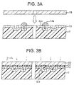
Next, as shown in Fig. 3A, an ultraviolet light
setting resin-based adhesive 14a is supplied onto the
second optical recording layer 13 and flattened by spin
coating etc. A flexible film 15 comprised of for example
polycarbonate and having a thickness of about 70 µm is
laid over the adhesive.
Next, as shown in Fig. 3B, ultraviolet light L is
irradiated from the flexible film 15 side to cure the
adhesive layer 14 and bond the flexible film 15 and the
second optical recording layer 13.
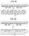
Next, as shown in Fig. 4A, the second optical
recording layer 13 and the transfer substrate T are
separated at their boundary. Due to this, the second
optical recording layer 13 is transferred to the flexible
film 15 side and a second stack 2 is obtained configured
with the second optical recording layer 13 bonded with
the flexible film 15 by an adhesive layer 14.
The aluminum film formed on the transfer substrate T
comprised of an acrylic resin by sputtering can be easily
separated without damaging the aluminum film. Further,
the flexible film 15 is pliable, which makes the
separation easier.
Next, as shown in Fig. 4B, the second stack 2 is
bonded on the first stack 1 formed in advance by an
adhesive layer 12 such as a pressure-sensitive adhesive
or an ultraviolet light setting resin-based adhesive.
Here, the first stack is formed by forming a
substrate 10 by for example injection molding etc., which
is comprised of a polycarbonate ,having a thickness of
for example 1.1 mm and formed with a pattern of
irregularities G11 for a first optical recording layer on
a surface thereof, depositing aluminum to for example a
thickness of 15 nm by for example sputtering on the top
of this, and thereby forming a reflection film having a
pattern corresponding to the above pattern of
irregularities G11, that is, the first optical recording
layer 11.
In the step of bonding the second stack 2 and the
first stack 1, the first optical recording layer 11 and
the second optical recording layer are bonded in the
state facing each other. Here, the distance between the
first optical recording layer 11 and the second optical
recording layer 13 (i.e., the thickness of the adhesive
layer 12) is several 10s of µm (for example 27 µm).
In the above way, the optical disk as shown in Fig.
1 can be produced.
According to the method of production of an optical
disk according to the present embodiment, the second
optical recording layer comprised of a thin semi-transparent
film can be easily transferred to the thin
flexible film, so the production is possible without
requiring the step of separating a stamper from a resin
cured by irradiating ultraviolet light and the step of
forming a semi-transparent film on a thin flexible film
as in the conventional method. Therefore, production is
possible without the accompanying difficulty in
separating the stamper and while avoiding the
difficulties in forming a semi-transparent film on a thin
flexible film.
Figure 5 is a cross-sectional view of an optical
disk according to the present embodiment.
A pattern of irregularities G21 for a first optical
recording layer is formed on a substrate 20 comprised of
for example polycarbonate and having a thickness of about
1.1 mm. On the top of this is formed, for example, a
reflection film comprised of a 15 nm thick aluminum and
having a pattern corresponding to the above pattern of
irregularities G21, that is, the first optical recording
layer 21. In this way, a first stack 1 is configured.
A semi-transparent film comprised of for example 5
nm thick aluminum and formed with a pattern of
irregularities in other steps in advance, that is, a
third optical recording layer 23, is adhered on the top
of the first optical recording layer 21 by an adhesive
layer 22 such as an ultraviolet light setting resin.
On the other hand, a semi-transparent film comprised
of for example 4 nm thick aluminum and formed with a
pattern of irregularities in other steps in advance, that
is, a second optical recording layer 25, is adhered on a
flexible film 27 comprised of for example polycarbonate
and having a thickness of a 50 µm or so by an adhesive
layer 26 such as an ultraviolet light setting resin. In
this way, a second stack 2 is configured.
The third optical recording layer 23 and the second
optical recording layer 25 are bonded together with them
facing each other by an adhesive layer 24 such as a
pressure-sensitive adhesive or an ultraviolet light
setting resin-based adhesive. Here, the distance between
the first optical recording layer 21 and the third
optical recording layer 23 (i.e., the thickness of the
adhesive layer 22) and the distance between the third
optical recording layer 23 and the second optical
recording layer 25 (i.e., the thickness of the adhesive
layer 24) are several 10s of µm (for example 25 µm),
respectively.
In the above way, an optical disk having three
optical recording layers according to the present
embodiment is configured.
The above optical disk is used for example as a
surface reading optical disk in which the first optical
recording layer 21, the second optical recording layer
25, and the third optical recording layer 23 are
positioned in a range of depth of about 100 µm from the
flexible film 27 side and the recorded information is
read from the flexible film 27 side.
Next, the method of production of the above optical
disk according to the present embodiment will be
described with reference to the drawings.
First, as shown in Fig. 6A, by for example injection
molding etc., a transfer substrate T is formed which is
comprised of an acrylic resin, having a thickness of for
example 1.1 mm and formed with a pattern of
irregularities G23 for a second optical recording layer
on a surface thereof. Next, aluminum, silver, or silicon
is deposited to a thickness of for example 5 nm by for
example sputtering on the transfer substrate T formed
with the pattern of irregularities G23 to form a semi-transparent
film that has a pattern corresponding to the
above pattern of irregularities G23, that is, the third
optical recording layer 23.
On the other hand, as shown in Fig. 6B, by for
example injection molding etc., a substrate 20 is formed
which is comprised of polycarbonate, having a thickness
of for example 1.1 mm and formed with a pattern of
irregularities G21 for a first optical recording layer on
a surface thereof. Next, aluminum etc. is deposited to a
thickness of, for example, 15 nm by, for example,
sputtering on the top of this to form a reflection film
that has a pattern corresponding to the above pattern of
irregularities G21, that is, the first optical recording
layer 21. In this way, the first stack 1 is configured.
Next, as shown in Fig. 6C, an ultraviolet light
setting resin-based adhesive 22a is supplied onto the
first optical recording layer 21 and flattened by spin
coating etc. The transfer substrate T formed with the
third optical recording layer 23 is laid over the
adhesive with the third optical recording layer 23 and
the first optical recording layer 21 facing each other.
Next, as shown in Fig. 7A, not illustrated
ultraviolet light is irradiated from the transfer
substrate T side to cure the adhesive layer 22 and bond
the third optical recording layer 23 with the first
optical recording layer 21, then the third optical
recording layer 23 and the transfer substrate T are
separated at their boundary. Due to this, the third
optical recording layer 23 is transferred to the first
stack 1 side. Here, the distance between the third
optical recording layer 23 and the first optical
recording layer 21 (i.e., the thickness of the adhesive
layer 22) is several 10s of µm (for example 25 µm).
The aluminum film formed on the transfer substrate T
comprised of an acrylic resin by sputtering can be easily
separated without damaging the aluminum film.
Next, as shown in Fig. 7B, the second stack 2 formed
in advance is bonded on the first stack 1 adhered with
the third optical recording layer 23 by the adhesive
layer 24 such as a pressure-sensitive adhesive or an
ultraviolet light setting resin-based adhesive.
Here, the second stack 2 can be formed in the same
way as in the first embodiment.
That is, by for example injection molding etc., a
transfer substrate is formed which is comprised of an
acrylic resin, having a thickness of for example 1.1 mm
and formed with a pattern of irregularities for a second
optical recording layer on a surface thereof. Next,
aluminum, silver, or silicon etc. is deposited to a
thickness of for example 4 nm by for example sputtering
on the transfer substrate T formed with the pattern of
irregularities to form a semi-transparent film that has a
pattern corresponding to the above pattern of
irregularities, that is, the second optical recording
layer 25. Next, an ultraviolet light setting resin-based
adhesive is supplied onto the second optical recording
layer 25 and flattened by spin coating, a flexible film
27 comprised of for example polycarbonate and having a
thickness of 50 µm or so is superimposed on this. Next,
ultraviolet light is irradiated from the flexible film 27
side to cure the adhesive layer 26. Then, the second
optical recording layer 25 and the transfer substrate are
separated at their boundary to obtain the second stack 2
of the above configuration.
In the step of bonding the second stack 2 to the
first stack 1 adhered with the third optical recording
layer 23, the third optical recording layer 23 and the
second optical recording layer 25 are bonded together
while facing each other. Here, the distance between the
third optical recording layer 23 and the second optical
recording layer 25 (i.e., the thickness of the adhesive
layer 24) is several 10s of µm (for example 25 µm).
In the above way, the optical disk as shown in Fig.
5 can be produced.
According to the above method of production of an
optical disk according to the present embodiment, the
second or third optical recording layer comprised of the
thin semi-transparent film can be easily transferred to
the thin flexible film, so the step of separating a
stamper from a resin cured by irradiating ultraviolet
light and the step of forming a semi-transparent film on
a thin flexible film as in the conventional method are
not necessary. Therefore, production is possible without
the accompanying difficulty in separating the stamper and
while avoiding the difficulties in forming a semi-transparent
film on a thin flexible film.
The above method of production of a multilayer
optical recording medium according to the present
embodiment is applicable to recording media including a
plurality of optical recording layers regardless of the
recording system.
The total number of optical recording layers is not
particularly limited. For example, in the second
embodiment, third optical recording layer may have a
multilayer structure wherein optical recording layers are
stacked via adhesive layers etc. In this case, all the
intermediate optical recording layers are made semi-transparent
films. Such multiple third optical recording
layers can be formed, for example, in the second
embodiment, by repeating the step of transfer an optical
recording layer from the transfer substrate to the first
stack.
In the above description, the third optical
recording layer is transferred onto the first optical
recording layer and the third optical recording layer and
the second optical recording layer are bonded together,
but it is possible that the third optical recording layer
is transferred onto the second optical recording layer,
and then, the third optical recording layer and the first
optical recording layer are bonded together in order.
The present invention is not limited to the above
embodiments.
For example, the materials, thicknesses, etc. of the
substrate, optical recording layers, adhesive layer
between layers, etc. which form the multilayer optical
recording medium are not limited to those described in
the above embodiments and can be suitably selected.
Numerous other modifications can also be made to an
extent not changing the gist of the present invention.
According to the method of production of the
multilayer optical recording medium of the present
invention, the step of separating a stamper from a resin
cured by irradiating ultraviolet light and the step of
forming a semi-transparent film on a thin flexible film
are not required and therefore production is possible
without the accompanying difficulty in separating the
stamper and while avoiding the difficulties in forming a
semi-transparent film on a thin flexible film.
While the invention has been described with
reference to specific embodiment chosen for purpose of
illustration, it should be apparent that numerous
modifications could be made thereto by those skilled in
the art without departing from the basic concept and
scope of the invention.
Claims (11)
- A method of production of a multilayer optical recording medium, comprising the steps of:forming a first optical recording layer on a substrate formed with a pattern of irregularities,forming a transfer substrate comprised of an acrylic resin formed with a pattern of irregularities on a surface thereof,forming a second optical recording layer on the pattern of irregularities of the transfer substrate,adhering a flexible film at the upper portion of the second optical recording layer by an adhesive layer,separating the second optical recording layer and the transfer substrate at their boundary to transfer the second optical recording layer to the flexible film, andbonding together the first optical recording layer and the second optical recording layer with them facing each other.
- A method of production of a multilayer optical recording medium as set forth in claim 1, wherein the first optical recording layer is formed by a reflection film.
- A method of production of a multilayer optical recording medium as set forth in claim 1, wherein the second optical recording layer is formed by a semi-transparent film.
- A method of production of a multilayer optical recording medium as set forth in claim 1, wherein the second optical recording layer is formed by sputtering.
- A method of production of a multilayer optical recording medium as set forth in claim 1, wherein the second optical recording layer is made from a material including at least one of aluminum, silver, and silicon.
- A method of production of a multilayer optical recording medium, comprising the steps of:forming a first optical recording layer on a substrate formed with a pattern of irregularities,forming a first transfer substrate comprised of an acrylic resin formed with a pattern of irregularities on a surface thereof,forming a second optical recording layer on the pattern of irregularities of the first transfer substrate,adhering a flexible film at the upper portion of the second optical recording layer by an adhesive layer,separating the second optical recording layer and the first transfer substrate at their boundary to transfer the second optical recording layer to the flexible film,forming a second transfer substrate comprised of an acrylic resin formed with a pattern of irregularities on a surface thereof,forming a third optical recording layer on the pattern of irregularities of the second transfer substrate,bonding together the third optical recording layer and the first optical recording layer with them facing each other,separating the third optical recording layer and the second transfer substrate at their boundary to transfer the third optical recording layer onto the first optical recording layer,bonding together the second optical recording layer and the third optical recording layer with them facing each other.
- A method of production of a multilayer optical recording medium as set forth in claim 6, wherein the third optical recording layer is formed by a semi-transparent film.
- A method of production of a multilayer optical recording medium as set forth in claim 6, wherein after the step of transferring the third optical recording layer onto the first optical recording layer, steps of forming a transfer substrate comprised of an acrylic resin formed with a pattern of irregularities on a surface thereof, forming an optical recording layer on the pattern of irregularities of the transfer substrate, and adhering the optical recording layer by an adhesive layer to transfer the optical recording layer are repeated.
- A method of production of a multilayer optical recording medium, comprising the steps of:forming a first optical recording layer on a substrate formed with a pattern of irregularities,forming a first transfer substrate comprised of an acrylic resin formed with a pattern of irregularities on a surface thereof,forming a second optical recording layer on the pattern of irregularities of the first transfer substrate,adhering a flexible film at the upper portion of the second optical recording layer by an adhesive layer,separating the second optical recording layer and the first transfer substrate at their boundary to transfer the second optical recording layer to the flexible film,forming a second transfer substrate comprised of an acrylic resin formed with a pattern of irregularities on a surface thereof,forming a third optical recording layer on the pattern of irregularities of the second transfer substrate,bonding together the third optical recording layer and the second optical recording layer with them facing each other,separating the third optical recording layer and the second transfer substrate at their boundary to transfer the third optical recording layer onto the second optical recording layer,bonding together the first optical recording layer and the third optical recording layer with them facing each other.
- A method of production of a multilayer optical recording medium as set forth in claim 9, wherein the third optical recording layer is formed by a semi-transparent film.
- A method of production of a multilayer optical recording medium as set forth in claim 9, wherein after the step of transferring the third optical recording layer onto the first optical recording layer, steps of forming a transfer substrate comprised of an acrylic resin formed with a pattern of irregularities on a surface thereof, forming an optical recording layer on the pattern of irregularities of the transfer substrate, and adhering the optical recording layer by an adhesive layer to transfer the optical recording layer are repeated.
Applications Claiming Priority (2)
| Application Number | Priority Date | Filing Date | Title |
|---|---|---|---|
| JP2000218646 | 2000-07-19 | ||
| JP2000218646A JP2002042379A (en) | 2000-07-19 | 2000-07-19 | Multilayer optical recording medium and method for manufacturing the same |
Publications (1)
| Publication Number | Publication Date |
|---|---|
| EP1174870A2 true EP1174870A2 (en) | 2002-01-23 |
Family
ID=18713565
Family Applications (1)
| Application Number | Title | Priority Date | Filing Date |
|---|---|---|---|
| EP01117217A Withdrawn EP1174870A2 (en) | 2000-07-19 | 2001-07-16 | Method of production of multilayer optical recording medium |
Country Status (7)
| Country | Link |
|---|---|
| US (1) | US6524418B2 (en) |
| EP (1) | EP1174870A2 (en) |
| JP (1) | JP2002042379A (en) |
| KR (1) | KR20020008049A (en) |
| CN (1) | CN1335614A (en) |
| SG (1) | SG91933A1 (en) |
| TW (1) | TW501129B (en) |
Families Citing this family (19)
| Publication number | Priority date | Publication date | Assignee | Title |
|---|---|---|---|---|
| CN1191578C (en) * | 1999-05-17 | 2005-03-02 | 索尼株式会社 | Disk-like multilayer information recording medium and production method thereof |
| US6723198B1 (en) * | 2001-05-24 | 2004-04-20 | Seagate Technology Llc | Servo pattern formation via transfer of sol-gel layer and magnetic media obtained thereby |
| TW559800B (en) * | 2001-11-27 | 2003-11-01 | Ind Tech Res Inst | Manufacturing method for multi-layer information storage medium |
| US7497916B2 (en) | 2002-03-27 | 2009-03-03 | Panasonic Corporation | Method of manufacturing multilayer optical information recording medium |
| ATE343838T1 (en) * | 2002-04-02 | 2006-11-15 | Koninkl Philips Electronics Nv | DOUBLE-LAYER OPTICAL DATA RECORDING MEDIUM |
| JP2004273079A (en) * | 2003-03-12 | 2004-09-30 | Fuji Photo Film Co Ltd | Transparent sheet for optical information recording medium, method for manufacturing same, and optical information recording medium |
| JP2004355701A (en) * | 2003-05-28 | 2004-12-16 | Toshiba Corp | Optical disk, method of manufacturing the same, and manufacturing apparatus |
| KR101138322B1 (en) * | 2004-06-30 | 2012-04-25 | 디아이씨 가부시끼가이샤 | Magnetic recording medium and magnetic recording medium manufacturing method |
| CN100342439C (en) * | 2004-08-27 | 2007-10-10 | 精碟科技股份有限公司 | Method for manufacturing optical information storage medium and method for determining template separation conditions |
| CN100378838C (en) * | 2005-04-01 | 2008-04-02 | 精碟科技股份有限公司 | Optical Information Storage Media |
| WO2006116885A1 (en) * | 2005-05-02 | 2006-11-09 | Unaxis Balzers Ag | Reusable stamper for optical disk |
| CN100429711C (en) * | 2005-06-16 | 2008-10-29 | 精碟科技股份有限公司 | Optical information storage medium |
| US20070045883A1 (en) * | 2005-08-30 | 2007-03-01 | Imation Corp. | Spin replicated flexible and concentrically registered stamper and stamped optical disk |
| CN100411035C (en) * | 2005-09-29 | 2008-08-13 | 精碟科技股份有限公司 | Optical information storage medium |
| EP1998373A3 (en) * | 2005-09-29 | 2012-10-31 | Semiconductor Energy Laboratory Co, Ltd. | Semiconductor device having oxide semiconductor layer and manufacturing method thereof |
| KR20070067995A (en) * | 2005-12-26 | 2007-06-29 | 엘지.필립스 엘시디 주식회사 | Manufacturing apparatus and method for manufacturing the flat panel display device |
| JP2007328873A (en) * | 2006-06-08 | 2007-12-20 | Toshiba Corp | Write-once multilayer optical disc, recording method, reproducing method, and recording apparatus |
| TWI416514B (en) * | 2008-05-23 | 2013-11-21 | Showa Denko Kk | Laminate for manufacturing a resin mold, laminate, resin mold, and manufacturing method of magnetic recording medium |
| JP4763073B2 (en) * | 2009-07-24 | 2011-08-31 | シャープ株式会社 | Optical information recording medium and manufacturing method thereof |
Family Cites Families (6)
| Publication number | Priority date | Publication date | Assignee | Title |
|---|---|---|---|---|
| US5708652A (en) * | 1995-02-28 | 1998-01-13 | Sony Corporation | Multi-layer recording medium and method for producing same |
| JP3605902B2 (en) * | 1995-10-16 | 2004-12-22 | ソニー株式会社 | Method for manufacturing multilayer optical recording medium |
| US5669995A (en) * | 1996-01-29 | 1997-09-23 | Hong; Gilbert H. | Method for writing and reading data on a multi-layer recordable interferometric optical disc and method for fabricating such |
| US5933409A (en) * | 1996-06-21 | 1999-08-03 | Sony Corporation | Optical recording medium and method for producing same |
| JP4026234B2 (en) * | 1998-06-19 | 2007-12-26 | ソニー株式会社 | Information recording medium |
| US6117284A (en) * | 1998-09-28 | 2000-09-12 | Wea Manufacturing, Inc. | Dual-layer DVD disc, and method and apparatus for making same |
-
2000
- 2000-07-19 JP JP2000218646A patent/JP2002042379A/en active Pending
-
2001
- 2001-07-09 TW TW90116689A patent/TW501129B/en not_active IP Right Cessation
- 2001-07-16 EP EP01117217A patent/EP1174870A2/en not_active Withdrawn
- 2001-07-17 US US09/907,370 patent/US6524418B2/en not_active Expired - Fee Related
- 2001-07-17 SG SG200104363A patent/SG91933A1/en unknown
- 2001-07-18 KR KR1020010043027A patent/KR20020008049A/en not_active Withdrawn
- 2001-07-19 CN CN01123362A patent/CN1335614A/en active Pending
Also Published As
| Publication number | Publication date |
|---|---|
| SG91933A1 (en) | 2002-10-15 |
| KR20020008049A (en) | 2002-01-29 |
| TW501129B (en) | 2002-09-01 |
| CN1335614A (en) | 2002-02-13 |
| US20020043328A1 (en) | 2002-04-18 |
| US6524418B2 (en) | 2003-02-25 |
| JP2002042379A (en) | 2002-02-08 |
Similar Documents
| Publication | Publication Date | Title |
|---|---|---|
| US6524418B2 (en) | Method of production of multilayer optical recording medium | |
| US5509991A (en) | Method of producing an optical disk having an integrated label layer | |
| EP1187122A2 (en) | Method and apparatus for producing an optical information recording medium, and optical information recording medium | |
| JPH11120617A (en) | Optical recording medium | |
| JPH11224439A (en) | Optical information recording carrier | |
| JPH08339574A (en) | Multi-layer optical disc | |
| KR100697136B1 (en) | Disk-type multilayer information recording medium and its manufacturing method | |
| JPH11232700A (en) | Optical recording medium and method for manufacturing optical recording medium | |
| JP2003091868A (en) | Optical disc and method of manufacturing the same. | |
| CN103578495A (en) | Optical recording medium and method for manufacturing optical recording medium | |
| JPH10222870A (en) | Optical recording medium | |
| WO2006003666A2 (en) | Multilayer optical disc and method and apparatus for making same | |
| JP2000036135A (en) | Method for manufacturing multilayer information recording medium | |
| JPH0997452A (en) | Method for manufacturing multilayer optical recording medium | |
| JP4360269B2 (en) | Multilayer optical disc manufacturing method | |
| JP5485287B2 (en) | Information recording medium manufacturing method and information recording medium | |
| KR100311146B1 (en) | Disk structure | |
| JPH08297859A (en) | Optical disc | |
| US20030185143A1 (en) | Multi-layer rewriteable information storage medium | |
| JP3671484B2 (en) | Optical recording medium | |
| JP2002334490A (en) | Method of manufacturing optical information recording carrier | |
| JPH0954985A (en) | Optical disk and method for manufacturing optical disk | |
| JPH08306085A (en) | Method for manufacturing multilayer optical recording medium | |
| JP4333624B2 (en) | Manufacturing method of optical recording medium | |
| WO2003012784A1 (en) | Optical recording medium, method of producing the same and protective film-forming resin |
Legal Events
| Date | Code | Title | Description |
|---|---|---|---|
| PUAI | Public reference made under article 153(3) epc to a published international application that has entered the european phase |
Free format text: ORIGINAL CODE: 0009012 |
|
| AK | Designated contracting states |
Kind code of ref document: A2 Designated state(s): AT BE CH CY DE DK ES FI FR GB GR IE IT LI LU MC NL PT SE TR |
|
| AX | Request for extension of the european patent |
Free format text: AL;LT;LV;MK;RO;SI |
|
| STAA | Information on the status of an ep patent application or granted ep patent |
Free format text: STATUS: THE APPLICATION HAS BEEN WITHDRAWN |
|
| 18W | Application withdrawn |
Effective date: 20031211 |