EP1174841A1 - Energiesparschaltung für eine Messeinrichtung - Google Patents
Energiesparschaltung für eine Messeinrichtung Download PDFInfo
- Publication number
- EP1174841A1 EP1174841A1 EP01116633A EP01116633A EP1174841A1 EP 1174841 A1 EP1174841 A1 EP 1174841A1 EP 01116633 A EP01116633 A EP 01116633A EP 01116633 A EP01116633 A EP 01116633A EP 1174841 A1 EP1174841 A1 EP 1174841A1
- Authority
- EP
- European Patent Office
- Prior art keywords
- current
- measuring device
- microprocessor
- power
- measuring
- Prior art date
- Legal status (The legal status is an assumption and is not a legal conclusion. Google has not performed a legal analysis and makes no representation as to the accuracy of the status listed.)
- Granted
Links
- 238000004891 communication Methods 0.000 claims description 18
- 238000000034 method Methods 0.000 claims description 11
- 230000008569 process Effects 0.000 claims description 9
- 230000001105 regulatory effect Effects 0.000 claims description 3
- 230000006978 adaptation Effects 0.000 claims description 2
- 230000003247 decreasing effect Effects 0.000 claims 1
- 238000005259 measurement Methods 0.000 description 18
- 230000006735 deficit Effects 0.000 description 6
- 230000005540 biological transmission Effects 0.000 description 2
- 238000006243 chemical reaction Methods 0.000 description 2
- 230000007423 decrease Effects 0.000 description 2
- 230000001419 dependent effect Effects 0.000 description 2
- 230000006870 function Effects 0.000 description 2
- 230000006872 improvement Effects 0.000 description 2
- 239000003990 capacitor Substances 0.000 description 1
- 230000001276 controlling effect Effects 0.000 description 1
- 230000005611 electricity Effects 0.000 description 1
- 238000005516 engineering process Methods 0.000 description 1
- 230000007274 generation of a signal involved in cell-cell signaling Effects 0.000 description 1
- 230000007257 malfunction Effects 0.000 description 1
- 238000004519 manufacturing process Methods 0.000 description 1
- 238000000691 measurement method Methods 0.000 description 1
- 238000005457 optimization Methods 0.000 description 1
- 230000009467 reduction Effects 0.000 description 1
- 239000000725 suspension Substances 0.000 description 1
Images





Classifications
-
- G—PHYSICS
- G08—SIGNALLING
- G08C—TRANSMISSION SYSTEMS FOR MEASURED VALUES, CONTROL OR SIMILAR SIGNALS
- G08C19/00—Electric signal transmission systems
- G08C19/02—Electric signal transmission systems in which the signal transmitted is magnitude of current or voltage
Definitions
- the invention relates to a measuring device for measuring an industrial process variable at a predetermined maximum power consumption by the measuring device. More specifically concerns the invention a measuring device for connection to a current loop, in particular a 4 - 20 mA current loop, or to a digital communication.
- Means for measuring a process variable are used to measure a process variable to be recorded and the measured values passed on for subsequent processing.
- UP ps
- the measured values can be passed on via a current loop or via a digital communication. In both cases, it is advantageous if the measuring device has its takes the required power from the two lines through which the measured value is passed on becomes.
- the current in the current loop set so that its size reflects the size of the process variable. It has a standard is now in use that uses currents between 4 mA and 20 mA, where a current of 4 mA through the current loop is the maximum (or minimum) measurement value and a current of 20 mA the minimum (or maximum) measured value of the process variable represents.
- This measurement technique proves to be largely insensitive to interference and is widely used experienced in industrial application.
- a measuring device that is supplied by means of a current loop has only a limited one Performance available. This power depends on the supply voltage and the (according to the currently set current). Conventional measuring devices are dimensioned so that they have the minimum available power get along, d. H. only the power available at minimum current and voltage need. If more power is available, this additional power is combined in one Current level converted into power loss and not in the measuring device for improvement used for the measurement.
- Measuring devices that are controlled via digital communication often have one constant power consumption as this is necessary for data transmission.
- the Available power depends on the applied terminal voltage.
- measuring devices are designed so that the measuring circuit maintains a constant Has power consumption that corresponds to the power with a minimum supply voltage. additionally Offered power with a larger supply voltage will also be dissipated here implemented.
- an improvement proposal is known in which an intelligent sensor is equipped with a sensor circuit.
- the sensor is used for a Measurement frequency operated, which corresponds to a power consumption that is greater than that at minimum current and minimum voltage available through the current loop. If this leads to a deficit (i.e. the power consumed exceeds the permissible one available power), then the sensor circuit detects this deficit and causes that the execution of the measurement program is suspended until the deficit no longer exists.
- the object of the invention is to provide a measuring device of the type mentioned at the outset is able to meet their power requirements without the risk of incorrect displays of the measured value adapt the available performance.
- the total output would be the one to be displayed Measured value, consumed by the corresponding frequent function of the sensor.
- Power remains, so there is no performance deficit and therefore no malfunction of the sensor can arise.
- the excess power is dissipated in the measuring device (Heat) implemented.
- Heat the measuring device
- the sum of both services taken must be just as large that the total current absorbed by the sensor corresponds to a defined value. This For the sensor, the value is to be output within a current loop (4 - 20 mA) by the current one Measured value specified.
- the value of the constant recorded corresponds Stroms the general requirements in connection with the used Communication protocol.
- the desired one Adaptation of the power consumed to carry out the measurement task enables the available service without exceeding it by the fact that the current surplus of power that would have to be converted into power loss becomes.
- the control unit of the sensor is in able to take appropriate measures regarding the type and frequency of implementation of the Measuring cycles the power consumption of the measuring device to the predetermined maximum available Approximate performance so that the surplus is minimized without a specific one to fall below the predetermined limit for the surplus. (The excess on this is ideal Limit at least approximately zero.)
- the current surplus can be determined either by measuring the surplus directly Electricity or excess power. But it is also indirect Way possible by measuring current or consumed power for implementation the measurement task and measurement of available performance or knowledge of Available current to determine the current surplus by forming a difference. If you choose the way of indirect surplus determination, you can make a significant simplification achieve with a slight disadvantage that individual measurements of the current or. Performance determination is waived and this through appropriate estimates and compliance larger reserves to be replaced.
- the invention is suitable for any measuring devices for process variables, if these Measuring devices externally a power consumption, usually a varying maximum power consumption is specified. For example, this is the default of Power consumption when using a current loop, because here (with the measured value to be displayed varies) only the maximum amount of power that may be used, corresponds to the current that is used to display the correct measured value in the supply lines can flow.
- the invention is particularly suitable for sensors such as level sensors.
- sensors such as level sensors.
- the invention is described below with reference to two embodiments, which are on the one hand a radar level sensor and on the other hand an ultrasonic level sensor is.
- Such sensors are regularly used today through current loops or digital communications and are therefore those to be overcome according to the invention Exposed to difficulties.
- a preferred implementation of the invention uses a current stage that is generally parallel to the other components of the measuring device.
- the current stage serves to consume the power (“power dissipation") that is left over from the total (given by the measured value display function) the power required deducts the measuring device in measuring mode. This one not used As already stated, the excess power is a measure of the reserve in the system for an increase in the measurement performance is still available without it being in the state of the Technology (EP 0 687 375) specified deficit comes.
- Such a current stage offers various options for measuring the excess power, as will be described below with reference to exemplary embodiments becomes.
- the current excess power can be measured directly. It can alternatively also be predicted.
- Known data from the measuring device for example, the relatively large power consumption of individual components become.
- connection of the measuring device to a digital communication, or an associated one Current loop enables completely analog measures to achieve the same advantages.
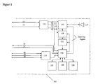
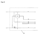
- a measuring device always consists of one generic part, which corresponds to Figures 1, 2 or 7, and a connection to the supply according to Figures 3 to 6 or 8 to 13.
- a first exemplary embodiment of a measuring arrangement according to the invention is a Radar level sensor.
- the sensor measures the level in a container.
- the measured Value is either via a current loop with z. B. 4 - 20 mA or via a digital Communication, e.g. B. a fieldbus.
- FIG. 1 shows part of such a radar sensor 101.
- the generic one is shown Part that is independent of how the measured value is passed on.
- a power supply unit 102 which has supply lines, is used to supply energy to the sensor 101 14 and 15 is connected to a current stage.
- the sensor is controlled by a microcontroller 106, whose program is in one Program memory 107 is located. It uses an EEPROM 109 and a for its data RAM 108.
- the microcontroller controls the RF front end 103, which generates radar signals sends the antenna 114 and processes the received signals. These signals are from Receiver 104 processed and digitized by means of an A / D converter 105 to the Microcontroller forwarded.
- the microcontroller determines from the digital signals a reading. After a possible conversion, he gives this via a control line 16 further to the current stage cf. below, which depending on this sets a current, or to the digital interface, which transmits the measured value via digital communication.
- the control lines 16 and 17 are used as a connection to the digital interface used.
- the microcontroller has the option of the HF front end, the receiver or other circuit parts via stand-by signals to put them into an idle state with reduced power consumption, or this entirely switch off as described below.
- the sensor may be used for measuring lines 18-20 and an A / D converter 110, which is connected to is connected to the microcontroller 106.
- the microcontroller has a reduced mode Current consumption. Capacitors 111, 112, and 113 reduce the current fluctuations, that arise when the components are switched on and off.
- Figure 2 shows a second exemplary embodiment of a similarly constructed ultrasonic sensor.
- a power supply unit 202 which has supply lines, is used to supply energy to the sensor 201 14 and 15 is connected to a current stage.
- the sensor is controlled by a microcontroller 206, the program of which is in one Program memory 207 is located. It uses an EEPROM 209 and a for its data RAM 208.
- the microcontroller controls the ultrasonic transmitter 203, the control signals for the sound transducer 214 supplies.
- the sound transducer 214 thereby generates sound waves that are emitted and reflected by a reflective medium.
- the received signals converts the sound transducer into electrical signals that are fed to the receiver 204.
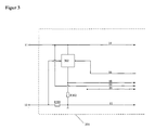
- FIG. 3 A first preferred implementation of the solution according to the invention for the exemplary embodiments according to Figures 1 and 2 is shown in Figure 3. It is used to measure the excess power, which are available for the optimization of the measuring device operation stands, by means of a current stage 302.
- Current stage 302 is connected at 11 and 12 to a 4-20 mA current loop.
- the current stage 302 is connected in parallel to the rest of the circuit of the measuring device.
- the Current stage monitors the total current via the voltage drop across a resistor R301 and keeps it constant.
- the current through the current stage is regulated so that the total current remains constant through the resistor R301 and that through the control line 16 corresponds to the specified value.
- the current that flows into the terminals of the measuring device is divided into a proportion that flows into the supply line 14, and a portion that flows into the current stage 302.
- the Current through the supply line 14 is used by the measuring device for working, the current through the current stage is not used to supply the measuring device, it is a measure of the current performance surplus.
- the microcontroller measures this excess, shown in FIG. 3 as a voltage measurement across a resistor R302, and adjusts the power consumption of the sensor so that it is always sufficient, if the smallest possible excess is available. If the surplus decreases, parts of the Measuring device z. B. the transmission and reception area, or the entire Signal generation and processing area put into a power-saving idle state. It is possible, with a corresponding reduction in the surplus, for a temporary suspension the operation as described in the prior art EP 0 687 375.
- Fluctuations can e.g. B. a brief increase in power consumption or a fluctuation in the supply voltage.
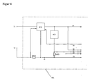
- Figure 4 shows alternative ways to build the current stage 402. It is here in series with the supply lines 14, 15. It is a Z-diode 403 alternatively one electronic circuit that has a variable current consumption depending on the voltage downstream. The electronic circuit is usually preferred.
- the total current of the complete measuring device is also over a Resistor R401 felt and regulated accordingly.
- the stream divides after the Current level to a part that is used to supply the measuring device.
- the determination of the excess power becomes more accurate if one also considers the voltage on the supply line + 14 with the measuring line 18.
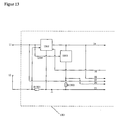
- FIG. 13 shows an improved circuit compared to FIG. 4.
- a current level 1302 is connected in series with the supply lines. Your is a circuit 1303 downstream, which consumes excess power. To do this, she feels the tension on the Supply line + 14 and with the help of a line 1304 the voltage before the current stage.
- the circuit 1303 consumes just enough current that the voltage drop across the Current stage 1302 is as small as possible to reduce power loss, but large enough remains so that the current stage can keep the current constant, even if the Supply voltages or the current consumption of the sensor occur.
- a measure of that Excess power therefore results from the current through the circuit 1303, the z. B. is measured via the voltage drop at R1302 using the measuring line 20.
- the determination of the excess power becomes more accurate if one also considers the voltage on the supply line + 14 with the measuring line 18.
- FIG. 5 shows a current stage 502 comparable to that in FIG. 3.
- R502 determines the current requirement of the measuring device. From the difference between the known current flowing in the current loop and the current requirement of the measuring device a measure of the excess can be derived from R502.
- the excess Performance more precisely through an additional measurement on the supply line + 14 available voltage can be determined by means of measuring line 19.
- FIG. 6 shows a current stage 602, similar to FIG. 4.
- the excess is not measured directly, but rather the input power at the terminals of the measuring device and the power consumption that the measuring device needed for supply, determined.
- the input power results from the known Current flowing in the current loop and the input voltage measured via measuring line 19.
- the power consumption that the measuring device requires for supply is calculated from the current through R602 and the voltage measured via measuring line 18 Supply + 14 determined. The difference between the two services is a measure of the currently pending Excess performance.
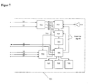
- the power consumption of the measuring device 101, 102 is often essentially determined by one or more large consumers. You get information about the power consumption of these components, one can make a statement about the power consumption of the Make measuring device by z. B. for the unknown power consumption of others Components assumes a worst case value. In addition, the available Performance determines how B. shown in Figures 3 to 6 and from it the excess power certainly. Based on the surplus performance, the Microcontroller whether parts of the measuring device are put into said idle state need to control the power consumption of the measuring device.
- Figure 7 shows as another preferred embodiment of the invention a radar sensor, which with the help of a Measurement line 715 receives a statement about the power consumption of the receiver 704. If the sensor is powered by a current loop or digital communication is irrelevant. In the case of an ultrasonic sensor or a sensor with a cable guided The same procedure can be carried out using radar. The important thing here is just one or more Identify main consumers whose current power requirements are determined.
- FIGS. 10 and 11 show further simplifications preferred according to the invention.
- the current currently required is included as a voltage drop across resistor R1002 Measured with the help of the measuring line 18 or via R1102 with the help of the measuring line 20.
- the Microcontroller can regulate this current by controlling the idle states so that it always stays below the currently available current.
- the current level 1202 keeps the current constant at times when there is no communication.
- the digital interface 1203 receives digital signals via the control line 16 from Microcontroller data, which it transmits in modulated form to the current stage, which the Current changed accordingly.
- the type of modulation depends on the specifications of the used digital communication.
- Data is received by the signals the supply line + 14 or at the current stage 1202 from the digital interface 1203 recognized and demodulated via the control line 17 to the microcontroller become.
- the measurement of the excess is implemented, as already shown in FIG. 3, by measuring the voltage drop via R1202 with the measuring line 18 or additionally the voltage on the supply line + 14 with the measuring line 19. The same are the other previously described methods on measuring devices with digital communication applicable.
Landscapes
- Physics & Mathematics (AREA)
- General Physics & Mathematics (AREA)
- Arrangements For Transmission Of Measured Signals (AREA)
- Measurement Of Current Or Voltage (AREA)
Abstract
Description
Claims (11)
- Messeinrichtung zur Messung einer Prozessvariablen bei vorgegebener maximaler Leistungsaufnahme durch die Messeinrichtung, insbesondere zum Anschluss an eine Stromschleife, wie etwa eine 4 - 20 mA Stromschleife, oder an eine digitale Kommunikation, mit Einrichtungen zur Regelung des Messbetriebs der Messeinrichtung in Anpassung an die vorgegebene Leistungsaufnahme, bei welcher die Regelungseinrichtungen (302, 402, 502, 602, 802, 902, 1002, 1102, 1202, 1302; 403, 603, 903, 1103, 1203, 1303; 106, 206, 706) die Leistungsaufnahme durch den Messbetrieb der Messeinrichtung (101, 201, 301, 401, 501, 601, 701, 801, 901, 1001, 1101, 1201, 1301) so regeln, dass diese Leistungsaufnahme der vorgegebenen Leistungsaufnahme angenähert wird, ohne dass die vorgegebene Leistungsaufnahme überschritten wird.
- Messeinrichtung nach Anspruch 1, bei der die vorgegebene Leistungsaufnahme durch einen vorgegebenen Strom und/oder eine vorgegebene Versorgungsspannung bestimmt ist.
- Messeinrichtung nach Anspruch 1, bei der die Regelungseinrichtung den Leistungsbedarf für den Messbetrieb der Messeinrichtung abhängig vom vorgegebenen Strom, von der Versorgungsspannung oder der aus beiden bestimmten Leistung einstellt.
- Messeinrichtung nach Anspruch 1, bei der die Regelungseinrichtung den Leistungsbedarf für den Messbetrieb der kompletten Messeinrichtung bzw. wenigstens eines Hauptverbrauchers (704) der Messeinrichtung (701) misst oder vorausschätzt und den Messbetrieb in Anspruch auf das Ergebnis regelt.
- Messeinrichtung nach Ansprüchen 1 - 4, bei der die Regelungseinrichtung den Leistungs-Überschuss misst oder vorausschätzt, um den die vorgegebene Leistungsaufnahme der Messeinrichtung die Leistungsaufnahme für den Messbetrieb übersteigt, und den Messbetrieb so regelt, dass der Leistungs-Überschuss minimiert wird.
- Messeinrichtung nach einem der Ansprüche 1 - 5, zum Anschluss an eine Stromschleife (11, 12) mit einem Mikroprozessor (106, 206, 706), einem Programmspeicher (107, 207, 707), der ein Programm zur Ausführung durch den Mikroprozessor speichert, einem oder mehreren EEPROM- und/oder RAM-Bausteinen (108, 208, 708; 109, 209, 709), Schaltungselementen (103, 104; 203, 204; 703, 704), die einen Betriebsmodus und einen stromsparenden Ruhezustand besitzen, und einer vom Mikroprozessor gesteuerten Stromstufe (302, 402, 502, 602, 802, 902, 1002, 1102, 1302), die die Größe eines in der Stromschleife fließenden Stromes derart regelt, dass sie auf vorgegebene Weise mit der Größe des Messwertes der Prozessvariablen korreliert, indem sie eine die Größe des Messwertes übertreffende Überschussleistung in der Stromstufe in Verlustleistung umsetzt, wobei abhängig vom eingestellten Strom durch die Stromschleife und/oder abhängig von der Versorgungsspannung die Ausführung des Messprogramms vom Mikroprozessor unterbrochen wird.
- Messeinrichtung nach Anspruch 6, bei der abhängig vom eingestellten Strom durch die Stromschleife und/oder von der Versorgungsspannung die Anzahl der Messzyklen pro Zeitintervall vom Mikroprozessor eingestellt wird.
- Messeinrichtung nach einem der Ansprüche 1 - 5, zum Anschluss an eine Stromschleife (11, 12) mit einem Mikroprozessor (106, 206, 706), einem Programmspeicher (107, 207, 707), der ein Programm zur Ausführung durch den Mikroprozessor speichert, einem oder mehreren EEPROM- und/oder RAM-Bausteinen (108, 208, 708; 109, 209, 709), Schaltungselementen (103, 104; 203, 204; 703, 704), die einen Betriebsmodus und einen stromsparenden Ruhezustand besitzen, und einer vom Mikroprozessor gesteuerten Stromstufe (302, 402, 502, 1302), die die Größe eines in der Stromschleife fließenden Stromes derart regelt, dass sie auf bestimmte vorgegebene Weise mit der Größe des Messwertes der Prozessvariablen korreliert, indem sie eine die Größe des Messwertes übertreffende Überschussleistung in der Stromstufe in Verlustleistung umsetzt, wobei die in der Stromstufe (302, 402, 502, 1302) in Verlustleistung umgesetzte Überschussleistung gemessen wird und, falls diese Überschussleistung über einem bestimmten vorgegebenen Wert liegt, die Anzahl der Messzyklen pro Zeitintervall vom Mikroprozessor erhöht wird, und, falls die Überschussleistung unter einem bestimmten vorgegebenen Wert liegt, die Anzahl der Messzyklen pro Zeitintervall vom Mikroprozessor erniedrigt wird.
- Messeinrichtung nach einem der Ansprüche 1 - 5, zum Anschluss an eine digitale Kommunikation (8, 9) mit einem Mikroprozessor (106, 206, 706), einem Programmspeicher (107, 207, 707), der ein Programm zur Ausführung durch den Mikroprozessor speichert, einem oder mehreren EEPROM- und/oder RAM-Bausteinen (108, 208, 708; 109, 209, 709), Schaltungselementen (103, 104; 203, 204; 703, 704), die einen Betriebsmodus und einen stromsparenden Ruhezustand besitzen, und einer vom Mikroprozessor gesteuerten Stromstufe (1202), wobei abhängig von der Versorgungsspannung die Ausführung des Messprogramms vom Mikroprozessor unterbrochen wird.
- Messeinrichtung nach Anspruch 9, bei der abhängig von der Versorgungsspannung die Anzahl der Messzyklen pro Zeitintervall vom Mikroprozessor eingestellt wird.
- Messeinrichtung nach einem der Ansprüche 1 - 5, zum Anschluss an eine digitale Kommunikation (8, 9), mit einem Mikroprozessor (106, 206, 706), einem Programmspeicher (107, 207, 707), der ein Programm zur Ausführung durch den Mikroprozessor speichert, einem oder mehreren EEPROM- und/oder RAM-Bausteinen (108, 208, 708; 109, 209, 709), Schaltungselementen (103, 104; 203, 204; 703, 704), die einen Betriebsmodus und einen stromsparenden Ruhezustand besitzen, und einer vom Mikroprozessor gesteuerten Stromstufe (1202), die eine Überschussleistung in der Stromstufe in Verlustleistung umsetzt, wobei die in der Stromstufe (1202) in Verlustleistung umgesetzte Überschussleistung gemessen wird und, falls diese Überschussleistung über einem bestimmten vorgegebenen Wert liegt, die Anzahl der Messzyklen pro Zeitintervall vom Mikroprozessor erhöht wird, und, falls die Überschussleistung unter einem bestimmten vorgegebenen Wert liegt, die Anzahl der Messzyklen pro Zeitintervall vom Mikroprozessor erniedrigt wird.
Applications Claiming Priority (2)
| Application Number | Priority Date | Filing Date | Title |
|---|---|---|---|
| DE2000134685 DE10034685B4 (de) | 2000-07-17 | 2000-07-17 | Energiesparschaltung |
| DE10034685 | 2000-07-17 |
Publications (2)
| Publication Number | Publication Date |
|---|---|
| EP1174841A1 true EP1174841A1 (de) | 2002-01-23 |
| EP1174841B1 EP1174841B1 (de) | 2015-04-01 |
Family
ID=7649188
Family Applications (1)
| Application Number | Title | Priority Date | Filing Date |
|---|---|---|---|
| EP20010116633 Expired - Lifetime EP1174841B1 (de) | 2000-07-17 | 2001-07-12 | Energiesparschaltung für eine Messeinrichtung |
Country Status (2)
| Country | Link |
|---|---|
| EP (1) | EP1174841B1 (de) |
| DE (1) | DE10034685B4 (de) |
Cited By (6)
| Publication number | Priority date | Publication date | Assignee | Title |
|---|---|---|---|---|
| EP1337987A1 (de) * | 2000-12-01 | 2003-08-27 | VEGA Grieshaber KG | Elektronische messvorrichtung zur erfassung einer prozesswvariablen, und verfahren zum betreiben einer solchen messvorrichtung |
| WO2007020141A1 (de) * | 2005-08-18 | 2007-02-22 | Endress+Hauser Gmbh+Co.Kg | Vorrichtung zur optimierung des leistungsverbrauchs einer elektrischen schaltungskomponente |
| WO2007022827A1 (de) * | 2005-08-26 | 2007-03-01 | Cedes Ag | Sensorvorrichtung |
| US7466748B2 (en) | 2000-01-12 | 2008-12-16 | Vega Grieshaber | Electronic measuring device for detecting a process variable, in particular a radar or ultrasonic filling level measuring device, and a method for operating a measuring device of this type |
| US10620653B2 (en) | 2018-04-05 | 2020-04-14 | Vega Grieshaber Kg | Measuring device with power management |
| DE102022119145A1 (de) * | 2022-07-29 | 2024-02-01 | Endress+Hauser Flowtec Ag | Anschlussschaltung für ein Feldgerät und Feldgerät |
Families Citing this family (2)
| Publication number | Priority date | Publication date | Assignee | Title |
|---|---|---|---|---|
| DE102022211796B4 (de) | 2022-11-08 | 2024-10-10 | Vega Grieshaber Kg | Verfahren zum Temperieren eines Messgeräts |
| DE102024106597A1 (de) | 2024-03-07 | 2025-09-11 | Endress+Hauser SE+Co. KG | Speisetrenner, Feldgerät und System aus Speisetrenner und Feldgerät |
Citations (4)
| Publication number | Priority date | Publication date | Assignee | Title |
|---|---|---|---|---|
| EP0319820A1 (de) * | 1987-12-11 | 1989-06-14 | Siemens Aktiengesellschaft | Datenverarbeitungssystem |
| US5416723A (en) * | 1993-03-03 | 1995-05-16 | Milltronics Ltd. | Loop powered process control transmitter |
| US5650571A (en) * | 1995-03-13 | 1997-07-22 | Freud; Paul J. | Low power signal processing and measurement apparatus |
| EP0895209A1 (de) * | 1997-07-21 | 1999-02-03 | Emerson Electric Co. | Verbesserte Leistungssteuerschaltung |
Family Cites Families (5)
| Publication number | Priority date | Publication date | Assignee | Title |
|---|---|---|---|---|
| DE2445337C2 (de) * | 1974-09-23 | 1986-05-15 | Philips Patentverwaltung Gmbh, 2000 Hamburg | Schaltungsanordnung zur Übertragung von elektrischen Meßwertsignalen |
| US4339750A (en) * | 1980-08-20 | 1982-07-13 | Rosemount Inc. | Low power transmitter |
| US4926340A (en) * | 1986-07-10 | 1990-05-15 | Rosemount Inc. | Low power process measurement transmitter |
| CA1311032C (en) * | 1989-03-31 | 1992-12-01 | Stanley Chlebda | Two-wire telemetering system including power regulated transmitting device |
| EP1147463B1 (de) * | 1998-11-03 | 2006-08-02 | AMETEK, Inc. | Hocheffiziente spannungsversorgung fuer eine zweidrahtschleifengespeisste vorrichtung |
-
2000
- 2000-07-17 DE DE2000134685 patent/DE10034685B4/de not_active Revoked
-
2001
- 2001-07-12 EP EP20010116633 patent/EP1174841B1/de not_active Expired - Lifetime
Patent Citations (4)
| Publication number | Priority date | Publication date | Assignee | Title |
|---|---|---|---|---|
| EP0319820A1 (de) * | 1987-12-11 | 1989-06-14 | Siemens Aktiengesellschaft | Datenverarbeitungssystem |
| US5416723A (en) * | 1993-03-03 | 1995-05-16 | Milltronics Ltd. | Loop powered process control transmitter |
| US5650571A (en) * | 1995-03-13 | 1997-07-22 | Freud; Paul J. | Low power signal processing and measurement apparatus |
| EP0895209A1 (de) * | 1997-07-21 | 1999-02-03 | Emerson Electric Co. | Verbesserte Leistungssteuerschaltung |
Cited By (8)
| Publication number | Priority date | Publication date | Assignee | Title |
|---|---|---|---|---|
| US7466748B2 (en) | 2000-01-12 | 2008-12-16 | Vega Grieshaber | Electronic measuring device for detecting a process variable, in particular a radar or ultrasonic filling level measuring device, and a method for operating a measuring device of this type |
| EP1337987A1 (de) * | 2000-12-01 | 2003-08-27 | VEGA Grieshaber KG | Elektronische messvorrichtung zur erfassung einer prozesswvariablen, und verfahren zum betreiben einer solchen messvorrichtung |
| WO2007020141A1 (de) * | 2005-08-18 | 2007-02-22 | Endress+Hauser Gmbh+Co.Kg | Vorrichtung zur optimierung des leistungsverbrauchs einer elektrischen schaltungskomponente |
| US8049371B2 (en) | 2005-08-18 | 2011-11-01 | Endress + Hauser Gmbh + Co. Kg | Device for optimising the energy consumption of an electric circuit component |
| WO2007022827A1 (de) * | 2005-08-26 | 2007-03-01 | Cedes Ag | Sensorvorrichtung |
| US7684018B2 (en) | 2005-08-26 | 2010-03-23 | Cedes Ag | Sensor device |
| US10620653B2 (en) | 2018-04-05 | 2020-04-14 | Vega Grieshaber Kg | Measuring device with power management |
| DE102022119145A1 (de) * | 2022-07-29 | 2024-02-01 | Endress+Hauser Flowtec Ag | Anschlussschaltung für ein Feldgerät und Feldgerät |
Also Published As
| Publication number | Publication date |
|---|---|
| DE10034685A1 (de) | 2002-01-31 |
| DE10034685B4 (de) | 2010-07-08 |
| EP1174841B1 (de) | 2015-04-01 |
Similar Documents
| Publication | Publication Date | Title |
|---|---|---|
| EP1301914B1 (de) | Messeinrichtung zur messung einer prozessvariablen | |
| EP0883097B1 (de) | Anordnung zur Signalübertragung zwischen einer Geberstelle und einer Empfangsstelle | |
| DE69932635T2 (de) | Hocheffiziente spannungsversorgung fuer eine zweidrahtschleifengespeisste vorrichtung | |
| EP1989519B1 (de) | Potentialtrennung für ein füllstandradar | |
| EP2806253B1 (de) | Messanordnung zur Bestimmung einer Messgröße | |
| EP2641062B1 (de) | MESSGERÄT ZUR BESTIMMUNG UND/ODER ÜBERWACHUNG MINDESTENS EINER PROZESSGRÖßE | |
| EP3447455B1 (de) | Füllstandmessgerät mit serieller anordnung von funktionseinheiten | |
| EP1337987A1 (de) | Elektronische messvorrichtung zur erfassung einer prozesswvariablen, und verfahren zum betreiben einer solchen messvorrichtung | |
| DE102014014695A1 (de) | Spannungsregler | |
| EP1103038A1 (de) | Schaltungsanordnung zur messwerterfassung, -übertragung und -auswertung | |
| EP3187836B1 (de) | Signallaufzeit-füllstandsensor mit langzeit-energiespeicher | |
| EP1174841B1 (de) | Energiesparschaltung für eine Messeinrichtung | |
| DE102006048594B4 (de) | Schaltungsanordnung zum kontaktlosen Datenaustausch und Chipkarte | |
| WO2007077081A1 (de) | Schaltungsanordnung zur versorgung eines feldgerätes der automatisierungstechnik | |
| WO2012084444A1 (de) | Messgerät | |
| DE102012113047A1 (de) | Betriebselektronik für ein Prozessgerät sowie Verfahren zum Betreiben derselben | |
| DE3782310T3 (de) | Zweidrahtübertragungssystem. | |
| DE102011112742A1 (de) | Verfahren zum Betreiben eines Kraftwagens, Schaltungsanordnung für einen Kraftwagen sowie Kraftwagen | |
| DE102017112755B4 (de) | Messumformerspeisegerät | |
| EP0613231B1 (de) | Verfahren und Schaltungsanordnung zum Einregeln einer Ausgangsspannung vorgegebener Höhe aus einer veränderlichen Eingangsspannung | |
| WO2004055480A1 (de) | Vorrichtung zur optimierung der leistungsbilanz eines sensors für die bestimmung und/oder überwachung einer physikalischen prozessgrösse eines mediums | |
| DE102023117252A1 (de) | Sendeeinheit und verfahren zum einkoppeln eines elektrischen sendesignals in eine gleichspannungsleitung | |
| WO2022023058A1 (de) | Mikrocontroller und system zur zweipunktregelung | |
| DE20014181U1 (de) | Sensormodul und Steuerungsanlage | |
| EP3070982A1 (de) | Empfangseinrichtung und verfahren zum betreiben einer empfangseinrichtung |
Legal Events
| Date | Code | Title | Description |
|---|---|---|---|
| PUAI | Public reference made under article 153(3) epc to a published international application that has entered the european phase |
Free format text: ORIGINAL CODE: 0009012 |
|
| AK | Designated contracting states |
Kind code of ref document: A1 Designated state(s): AT BE CH CY DE DK ES FI FR GB GR IE IT LI LU MC NL PT SE TR Kind code of ref document: A1 Designated state(s): DE FR GB |
|
| AX | Request for extension of the european patent |
Free format text: AL;LT;LV;MK;RO;SI |
|
| 17P | Request for examination filed |
Effective date: 20020619 |
|
| AKX | Designation fees paid |
Free format text: DE FR GB |
|
| 17Q | First examination report despatched |
Effective date: 20060518 |
|
| GRAP | Despatch of communication of intention to grant a patent |
Free format text: ORIGINAL CODE: EPIDOSNIGR1 |
|
| INTG | Intention to grant announced |
Effective date: 20141023 |
|
| GRAS | Grant fee paid |
Free format text: ORIGINAL CODE: EPIDOSNIGR3 |
|
| GRAA | (expected) grant |
Free format text: ORIGINAL CODE: 0009210 |
|
| AK | Designated contracting states |
Kind code of ref document: B1 Designated state(s): DE FR GB |
|
| REG | Reference to a national code |
Ref country code: GB Ref legal event code: FG4D Free format text: NOT ENGLISH |
|
| REG | Reference to a national code |
Ref country code: DE Ref legal event code: R096 Ref document number: 50116467 Country of ref document: DE Effective date: 20150521 |
|
| REG | Reference to a national code |
Ref country code: DE Ref legal event code: R097 Ref document number: 50116467 Country of ref document: DE |
|
| PLBE | No opposition filed within time limit |
Free format text: ORIGINAL CODE: 0009261 |
|
| STAA | Information on the status of an ep patent application or granted ep patent |
Free format text: STATUS: NO OPPOSITION FILED WITHIN TIME LIMIT |
|
| 26N | No opposition filed |
Effective date: 20160105 |
|
| REG | Reference to a national code |
Ref country code: FR Ref legal event code: PLFP Year of fee payment: 16 |
|
| REG | Reference to a national code |
Ref country code: FR Ref legal event code: PLFP Year of fee payment: 17 |
|
| REG | Reference to a national code |
Ref country code: FR Ref legal event code: PLFP Year of fee payment: 18 |
|
| PGFP | Annual fee paid to national office [announced via postgrant information from national office to epo] |
Ref country code: DE Payment date: 20180725 Year of fee payment: 18 Ref country code: FR Payment date: 20180723 Year of fee payment: 18 |
|
| PGFP | Annual fee paid to national office [announced via postgrant information from national office to epo] |
Ref country code: GB Payment date: 20180725 Year of fee payment: 18 |
|
| REG | Reference to a national code |
Ref country code: DE Ref legal event code: R119 Ref document number: 50116467 Country of ref document: DE |
|
| GBPC | Gb: european patent ceased through non-payment of renewal fee |
Effective date: 20190712 |
|
| PG25 | Lapsed in a contracting state [announced via postgrant information from national office to epo] |
Ref country code: DE Free format text: LAPSE BECAUSE OF NON-PAYMENT OF DUE FEES Effective date: 20200201 Ref country code: GB Free format text: LAPSE BECAUSE OF NON-PAYMENT OF DUE FEES Effective date: 20190712 |
|
| PG25 | Lapsed in a contracting state [announced via postgrant information from national office to epo] |
Ref country code: FR Free format text: LAPSE BECAUSE OF NON-PAYMENT OF DUE FEES Effective date: 20190731 |