EP1174827A2 - Image processing apparatus and control method therefor - Google Patents
Image processing apparatus and control method therefor Download PDFInfo
- Publication number
- EP1174827A2 EP1174827A2 EP01306199A EP01306199A EP1174827A2 EP 1174827 A2 EP1174827 A2 EP 1174827A2 EP 01306199 A EP01306199 A EP 01306199A EP 01306199 A EP01306199 A EP 01306199A EP 1174827 A2 EP1174827 A2 EP 1174827A2
- Authority
- EP
- European Patent Office
- Prior art keywords
- color
- characteristic
- degree
- transformation information
- color transformation
- Prior art date
- Legal status (The legal status is an assumption and is not a legal conclusion. Google has not performed a legal analysis and makes no representation as to the accuracy of the status listed.)
- Withdrawn
Links
Images

















Classifications
-
- G—PHYSICS
- G06—COMPUTING OR CALCULATING; COUNTING
- G06T—IMAGE DATA PROCESSING OR GENERATION, IN GENERAL
- G06T11/00—Two-dimensional [2D] image generation
- G06T11/10—Texturing; Colouring; Generation of textures or colours
Definitions
- the present invention relates to an image processing apparatus and its control method which properly reproduce the same image data in a plurality of image input/output apparatuses.
- CMS Color Management System
- a CMS will be described by exemplifying the case where a plurality of apparatuses such as a color printer, color monitor, and color copying machine are connected to each other, as shown in Fig. 31.
- a color signal in an input system is transformed into a color signal in an output system. More specifically, an input color signal is transformed into a signal in a color space independent of an apparatus (to be referred to as a device-independent color space hereinafter) by using a predetermined transformation formula or table associated with an input apparatus.
- the predetermined transformation formula or table used to transform a signal in a color space dependent on an apparatus into a signal in a device-independent color space will be referred to as a profile for the apparatus.
- the signal value is transformed into a signal in a color space dependent on each output apparatus by referring to a profile for each output apparatus.
- color matching between a plurality of apparatuses can be realized by transforming a color signal in a color space dependent on each apparatus into a color signal in a device-independent color space on the basis of the profile for each apparatus.
- the CIE/XYZ color space CIE/L*a*b* color space, or the like which is a color space used for colorimetry of an image output from an output apparatus is used.
- a profile for each apparatus is created on the basis of the relationship between each color signal value and the value obtained by actual colorimetry of a visible image input to the apparatus or output therefrom.
- a profile for an input apparatus is created by using a sample image as an original which is based on a predetermined color signal on the basis of an input image signal obtained through the apparatus.
- a profile for an output apparatus is created by outputting a sample image based on a predetermined color signal in the apparatus and colorimetrically measuring the output sample image.
- the color reproduction characteristic of an image input/output apparatus does not necessarily remain the same at the time of creating of a profile and at the time of execution of a CMS using the profile. This phenomenon occurs when the color reproduction characteristic of an image output apparatus varies more or less due to differences between parts such as color material lots in the apparatuses, environmental differences such as temperature/humidity differences, changes in the quality of image forming components and the like over time, or the like.
- the color reproduction characteristic changes after the creation of a profile, the relationship between each color signal and the corresponding colorimetric value of an output image, which is reflected in the profile, changes. Obviously, therefore, when the CMS is executed without any change, a proper color reproduction result cannot be obtained.
- the conventional CMS provides no means for allowing a user or person who maintains a profile (to be referred to as a profile manager hereinafter) to check a change in the color reproduction characteristic of an image input/output apparatus and determine the validity of the profile. For this reason, profile update processing is not always performed at a proper timing.
- the present invention has been proposed to solve the conventional problems, and has as a concern to provide an image processing apparatus and its control method, which can perform stable color processing regardless of variations in color reproduction characteristic in an image input/output apparatus.
- a method of controlling an image processing apparatus for performing color transformation based on color transformation information unique to a connected device comprising:
- color transformation information can be generated in consideration of the degree of stability of color reproduction in a device, proper color reproduction can be performed in the device.
- Fig. 1 is a view showing the schematic arrangement of an image processing system for executing a CMS according to this embodiment.
- the image processing system according to this embodiment is comprised of an input apparatus 1, image processing apparatus 30, and output apparatus 5.
- the image processing apparatus 30 includes an image input unit 2, image processing unit 3, and image output unit 4.
- the color image data input from the input apparatus 1 to the image processing apparatus 30 through the image input unit 2 is transformed into data in a device-independent color space that does not depend on any devices in the image processing unit 3.
- the resultant data is output to the output apparatus 5 through the image output unit 4.
- the output apparatus 5 is an apparatus for visualizing an image, and typified by a display for displaying an image, a printer for forming an image on a recording medium, and the like.
- the input apparatus 1 is an apparatus for generating image data, and typified by a scanner for reading an image on a recording medium and the like as well as an image sensing apparatus and computer.
- the device-independent color space is, for example, the CIE/L*a*b* color space used for colorimetry.
- the image processing unit 3 also includes an input-side color space transformation unit 31, color gamut compression processing unit 32, output-side color space transformation unit 33, profiles 34 and 35, and profile controller 36.
- the input-side color space transformation unit 31 transforms the color image data input from the input apparatus 1 through the image input unit 2, i.e., the color image data in the color space dependent on the color reproduction range of the input apparatus 1, into data in the device-independent color space on the basis of the profile 34.
- the color gamut compression processing unit 32 performs color gamut compression processing for the color image data in the device-independent color space supplied through the input-side color space transformation unit 31 to transform the data into data in a color gamut in which the output apparatus 5 can reproduce the data.
- the output-side color space transformation unit 33 transforms on the basis of the profile 35 the color image data in the device-independent color space, which has undergone the color gamut compression processing by the color gamut compression processing unit 32, into color image data in the color space dependent on the color reproduction range of the output apparatus 5, and then outputs the resultant data to the output apparatus 5 through the image output unit 4.
- predetermined transformation formulae or tables are retained as the profiles 34 and 35 in advance for the respective apparatuses.
- the profile controller 36 controls the profiles 34 and 35 to always keep them in an optimum state.
- a profile is properly updated to reflect the current color reproduction characteristic in an output apparatus on the basis of the colorimetric value estimated by the profile, an average colorimetric value in the current output image in the image output apparatus, and variations in colorimetric value.
- Fig. 2 is a flow chart showing a procedure for updating the profile 35 for a CMS in this embodiment.
- n a proper sampling count n is determined in advance to check the current color reproduction characteristic in the output apparatus 5, and n color signals are output to check the color reproduction characteristic (step S101).
- an average value m ((L* ave , a* ave , b* ave ) of each colorimetric value m i is calculated as an average along each axis in the device-independent color space (step S104).
- This average value m represents the sample average of the current color reproduction characteristic in the output apparatus 5.
- a colorimetric value (estimated value) M corresponding to the above color signal is obtained by using the existing profile 35 (step S105).
- a t-statistic T is calculated according to equation (4) using this difference S (step S107).
- T S n /2 U 2
- ⁇ 2.87 at a significant level of 0.01 (1%). Consequently, if, for example, n 10, and T is larger than 2.87 (step S108), the hypothesis is rejected at a significant level of 1%. That is, since the difference S is significant, the existing profile 35 contradicts the current color reproduction characteristic. In other words, it is evaluated that the existing profile 35 does not reflect the current color reproduction characteristic. Therefore, the profile 35 is updated on the basis of the current colorimetric value (step S109). If T is 2.87 or less, the hypothesis is accepted. That is, it is evaluated that the difference S in colorimetric value is not significant and is coincidentally produced, and the existing profile 35 sufficiently reflects the current color reproduction characteristic. The existing profile 35 is not therefore updated and is kept used without any change (step S110).
- the profile updating method in step S109 is not specifically defined, the average colorimetric value m acquired in step S104 may be directly used or the method in the ninth to 11th embodiments may be used.
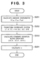
- Fig. 3 is a flow chart showing a procedure for calculating the variation evaluation index U in step S103 in Fig. 2.
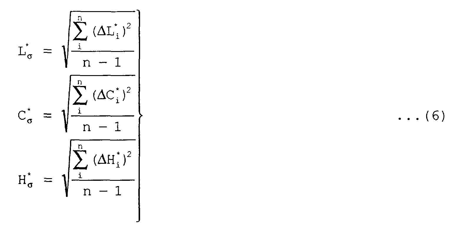
- the variation evaluation index U is obtained by applying the CIE1994 color difference formula to variances in the directions of lightness, chroma (saturation), and hue. With this index, 3D variations can be easily handled.
- average coordinates m(L* ave , a* ave , b* ave ) in the CIE/L*a*b* color space are obtained by equations (1) (step S201).
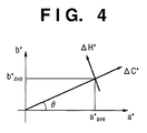
- ⁇ L, ⁇ C, and ⁇ H respectively correspond to a lightness difference, chroma difference, and hue difference corresponding to the average values.
- Fig. 4 shows the relationship between the (a*, b*) coordinate system and the ( ⁇ C, ⁇ H) coordinate system.
- whether the existing profile 35 reflects the current color reproduction characteristic in the image output apparatus can be determined on the basis of the colorimetric value estimated by the profile 35, the average colorimetric value in the current output image from the apparatus, and variations in colorimetric value. By deciding whether to update the profile 35 in accordance with the determination result, an optimal color reproduction characteristic can always be maintained in the profile.
- This embodiment has exemplified the update processing for the profile 35 associated with the output apparatus 5.
- the present invention can be equally applied to the input apparatus 1. That is, this embodiment has exemplified the processing based on the average colorimetric value of sample images output from the output apparatus 5.
- the profile 34 associated with the input apparatus 1 can also be updated properly in the same manner as described above. This technique is especially effective when the input apparatus 1 is a scanner for reading images.
- a colorimetric value and the like at the time of creation of a profile in an image output apparatus are retained as additional information, together with the profile.
- whether the profile reflects the current color reproduction characteristic is determined on the basis of the retained colorimetric value, the average colorimetric value of the current output image from the apparatus, and variations in colorimetric value.
- n color signals for a color reproduction characteristic check are output as a predetermined sampling count (step S301), and the output image is colorimetrically measured (step S302).
- an average value m of the colorimetric values is calculated according to equations (1) (step S303).
- a root sum square ⁇ of the color differences between the respective colorimetric values m i is calculated according to equation (8) (step S304).
- the average value m, color difference root sum square ⁇ , and sampling count n are retained as additional information in the profile created on the basis of the colorimetric values m i or a memory or the like (not shown) in an image processing unit 3 in correspondence with the profile (step S305).
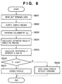
- step S401 the additional information retained at the time of creation of a profile is read out (step S401).
- a proper sampling count n' is then determined, and n' color signals for a color reproduction characteristic check are output (step S402) to colorimetrically measure the output image (step S403).
- an average value m' of the colorimetric values is calculated according to equations (1) (step S404).
- a root sum square ⁇ ' of the color differences between the colorimetric values is calculated according to equation (8) (step S405).
- a difference S between the average value m at the time of creation of the profile and a current average value m' is calculated according to equation (9) (step S406).
- S ⁇ E 1994 (m,m')
- T S ⁇ nn'(n+n'-2)/( ⁇ + ⁇ ') (n+n') ⁇
- whether the existing profile reflects the current color reproduction characteristic in the image output apparatus can be determined on the basis of the colorimetric value at the time of creation of the profile, the average colorimetric value in the current output image from the apparatus, and variations in colorimetric value. By deciding whether to update the profile in accordance with the determination result, an optimal color reproduction characteristic can always be maintained in the profile as in the first embodiment described above.
- a variation evaluation index U at the time of creation of a profile in an image output apparatus is retained as additional information, together with the profile. According to a characteristic feature of this embodiment, whether the profile reflects the current color reproduction characteristic is checked on the basis of the retained variation evaluation index U and the average colorimetric value of the current output image from the apparatus.
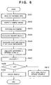
- n color signals for a color reproduction characteristic check are output as a predetermined sampling count (step S501), and the output image is colorimetrically measured (step S502).
- the color variation evaluation index U is calculated in accordance with the flow chart of Fig. 3 (step S503).
- This variation evaluation index U is retained as additional information in the profile created on the basis of the colorimetric value m i or a memory or the like (not shown) in the image processing unit 3 in correspondence with the profile (step S504).
- step S601 The value of the retained variation evaluation index U is read out (step S601).
- a proper sampling count n is then determined, and n color signals for a color reproduction characteristic check are output (step S602) to colorimetrically measure the output image to obtain a colorimetric value m (step S603).
- a colorimetric value M corresponding to the above color signal is obtained by using the existing profile (step S604), and a difference S between these values M and m is calculated according to equation (3) (step S605).
- step S606 Letting M be the estimated population mean of colors output from the apparatus in accordance with the above color signal, and U 2 be the estimated population variance, S ⁇ 2.58U at a significant level of 0.01 if the characteristics of the apparatus have not changed. If, therefore, S exceeds 2.58U (step S606), it is determined that the existing profile differs from the current color reproduction characteristic, and the profile is updated (step S607). If S is 2.58 or less, it is determined that the color reproduction characteristic remains unchanged, the existing profile is kept used without any change (step S608).
- the variation evaluation index U at the time of creation of a profile is retained, and whether the profile reflects the current color reproduction characteristic is determined by using the variation evaluation index U.
- the variation evaluation index U In determining the necessity to update a profile, there is no need to calculate the variation evaluation index U as in the first and second embodiments, and hence the determination result can be obtained faster.
- CIE/L*a*b* color space and CIE1994 color difference formula are used as a device-independent color space and color different formula, respectively.
- another color space such as the CIE/XYZ or CIE/L*u*v* color space and another color difference formula such as the CIE1976, CMC, BFD, or MLAB color difference formula may be used.
- the user may be notified of the corresponding information instead of unconditional execution of profile updating. Thereafter, whether to update the profile may be determined in accordance with an instruction from the user.
- an output-side color space transformation unit 33 obtains the difference between the colorimetric value estimated by an existing profile 35 and the colorimetric value in the current output image from an output apparatus 5 as a colorimetric value estimation error. By presenting the obtained estimated value to a profile manager, the profile manager can determine the validity of the current profile.
- Fig. 9 is a view showing a detailed arrangement for implementing profile evaluation processing according to the fourth embodiment mainly in a profile controller 36.
- the profile controller 36 is comprised of a profile retention unit 201, check image retention unit 202, image output unit 203, colorimetric value input unit 204, colorimetric value estimation unit 205, estimation error computation unit 206, measurement result retention unit 207, estimation result retention unit 208, estimation error retention unit 209, and result output unit 210.
- a colorimetry apparatus 211, image output apparatus 212, and estimation error output apparatus 213 are connected to the profile controller 36.
- the image output apparatus 212 corresponds to the output apparatus 5 in Fig. 1, and the profile 35 is loaded in the profile retention unit 201.
- the check image retention unit 202 stores predetermined color image data used to check a colorimetric value estimation error. This color image data is visualized/output onto a printing sheet by the image output apparatus 212 through the image output unit 203. The output image is colorimetrically measured by the colorimetry apparatus 211, and the colorimetry result is stored in the measurement result retention unit 207 through the colorimetric value input unit 204.
- a profile for the image output apparatus 212 is stored in the profile retention unit 201.
- the colorimetric value estimation unit 205 estimates the colorimetric value of the color image data stored in the check image retention unit 202 by using the profile, and stores the estimation result in the estimation result retention unit 208.
- the estimation error computation unit 206 obtains an estimation error as the color difference between the actual colorimetric value reflecting the current color reproduction characteristic, stored in the measurement result retention unit 207, and the estimated colorimetric value based on the current profile, stored in the estimation result retention unit 208, and stores the result in the estimation error retention unit 209.
- the result output unit 210 outputs the estimation error stored in the estimation error retention unit 209 to the estimation error output apparatus 213.
- the colorimetry apparatus 211 is an apparatus capable of obtaining a colorimetric value such as CIE/L*a*b* with respect to the color of a visualized image, and is typified by a spectroreflectometer, a colorimeter, or a high-resolution color scanner with an input profile.
- the estimation error output apparatus 213 is an apparatus for presenting the colorimetric value estimation error based on the existing profile to the profile manager, and is typified by a display, printer, and the like.
- the colorimetric value input unit 204 is a unit for inputting an output from the colorimetry apparatus 211 to the profile controller 36 by using some means, and is typified by a keyboard, disk, network, and the like.
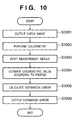
- Fig. 10 is a flow chart showing a procedure for outputting a colorimetric value estimation error in the fourth embodiment.
- the color image data stored in the check image retention unit 202 is output from the image output apparatus 212 through the image output unit 203 (step S3301).
- the colorimetry apparatus 211 measures a predetermined portion of the output image (step S3302).
- the colorimetric value input unit 204 inputs the colorimetric value obtained by the colorimetry apparatus 211 and stores it in the measurement result retention unit 207 (step S3303).
- the colorimetric value estimation unit 205 estimates a colorimetric value corresponding to a predetermined portion of the color image data stored in the check image retention unit 202 by using the profile stored in the profile retention unit 201, and stores the estimation result in the estimation result retention unit 208 (step S3304).
- the estimation error computation unit 206 calculates an estimation error on the basis of the measurement result stored in the measurement result retention unit 207 and the estimation result stored in the estimation result retention unit 208, and stores the result in the estimation error retention unit 209 (step S3305).
- the result output unit 210 outputs (e.g., display) the estimation error stored in the estimation error retention unit 209 to the estimation error output apparatus 213 (step S3306).
- the estimation error check image stored in the check image retention unit 202 will be described below.
- Fig. 11 shows an example of the color image data stored in the check image retention unit 202.
- This color image data is constituted by color chips evenly extracted from the color space dependent on the image output apparatus 212. Each color chip has a size large enough to be measured by the colorimetry apparatus 211.
- the respective values of [R, G, B] represent 729 colors constituted by the elements of a set ⁇ 0, 32, 64,..., 224, 255 ⁇ , i.e., [0, 0, 0], [0, 0, 32], [0, 0, 64],..., [0, 0, 224], [0, 0, 255], [0, 32, 0], [0, 32, 32],..., [255, 255, 255].
- color image data used for an estimation error check is not limited to the example shown in Fig. 11.
- step S3302 colorimetry is performed for each color chip in the output image from the image output apparatus 212.
- step S3304 a colorimetric value corresponding to the color signal of each color chip is estimated by using the transformation formula or table held in the profile.
- Fig. 12 shows a display example of the output image.
- the output image shown in Fig. 12 displays an average value 501 and maximum value 502 of estimation errors.
- an estimation error is the color difference between the measurement result on the current output image from the image output apparatus 212, input in step S3303, and the colorimetric value estimated from the existing profile, obtained in step S3304.
- the average and maximum value of the estimation errors (the color differences) in the above 729 colors are calculated and displayed.
- a color difference may be calculated by using the CIE1994 color difference formula represented by equation (2). That is, co11 and co12 in equation (2) respectively correspond to the measurement result input in step S3303 and the colorimetric value estimation result calculated in step S3304.
- the profile manager can check the average value and maximum value of estimation errors, and hence can determine the validity of the profile. For example, if the displayed estimation error is large, the profile manager determines that the profile must be updated to realize good color reproduction by using a CMS.
- the difference between the colorimetric value estimated on the basis of the existing profile and the colorimetric value in the current output image form the image output apparatus can be checked.
- the profile manager can check the color reproduction precision based on the existing profile, i.e., whether the profile properly reflects the current color reproduction characteristic of the apparatus, and hence can determine whether to update the profile.
- the profile manager can therefore always maintain each profile in an optimal state.
- the profile manager properly manages the profiles in a plurality of image output apparatuses.
- color reproduction intended by the profile manager can be realized in each apparatus.
- colorimetric value estimation errors associated with the output apparatus 5 have been described.
- the present invention can be equally applied to an input apparatus 1. More specifically, in the fourth embodiment, an estimation error is obtained on the basis of the difference between the colorimetric value estimated from color image data and the colorimetric value of the image output from the output apparatus 5.
- an estimation error can be obtained in the input apparatus 1 in the same manner as described above.
- the fifth embodiment of the present invention will be described below.
- the arrangement of an image processing apparatus and a profile estimation method according to the fifth embodiment are the same as those described with reference to Figs. 1, 9, and 10, and hence a description thereof will be omitted.
- colorimetric value estimation errors based on an existing profile are output in association with a plurality of colors.
- the color image data for an estimation error check which is stored in a check image retention unit 202 is constituted by color chips of colors expected to often exist in photographic images taken by a camera, e.g., a skin color, azure, and verdure.
- this color image data may be constituted by color chips of colors expected to be often used in business documents, tables, and graphs or colors often used in computer graphics (CG). That is, the above color image data is constituted by color chips of colors considered important in general color images.
- color image data for an estimation error check may be formed by mixing a color chip for a photographic image, a color chip for a business document, and a color chip for CG.
- estimation errors for the existing profile are calculated for colors considered important in a general image and output.
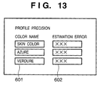
- Fig. 13 shows an example of how estimation errors are displayed in the fifth embodiment. According to the display example shown in Fig. 13, pairs of color names 601 and estimation errors 602 are output for the respective colors.
- the profile manager can check an estimation error about each color and determine the validity of the existing profile in accordance with the application purpose of the image output apparatus, colors considered important in an output target image, and the like.
- a colorimetric value estimation error based on the existing profile is output in association with an arbitrary color signal.
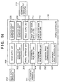
- Fig. 14 shows the arrangement of a profile controller 36 in the sixth embodiment.
- a characteristic feature of the arrangement shown in Fig. 14 is that it includes a check color signal input UI (User Interface) unit 714 and check color signal retention unit 715 in addition to the arrangement shown in Fig. 9 in the fourth embodiment.
- the check color signal input UI unit 714 has a color signal input UI and final color signal check UI, and inputs a check color signal upon user operation.
- the check color signal retention unit 715 stores one or a plurality of sets of estimation error check color signals input through the check color signal input UI unit 714. Note that the same reference numerals as in Fig. 9 denote the same parts in Fig. 14, and a description thereof will be omitted.
- Fig. 15 is a flow chart showing a procedure for outputting a colorimetric value estimation error in the sixth embodiment.
- the check color signal input UI unit 714 inputs a check color signal through the color signal input UI, and stores the signal in the check color signal retention unit 715 (step S3801).
- the check color signal input UI unit 714 inputs through the final color signal check UI a user instruction to indicate whether to keep inputting a check color signal (step S3802). If input operation is to be continued, the flow returns to step S3801. If the input operation is to be terminated, the flow advances to step S3803.
- step S3803 Upon completion of the input operation for the check color signal, on the basis of the color signal stored in the check color signal retention unit 715, color image data for a colorimetric value estimation error check which is constituted by the color chip of the color signal is generated (step S3803), and is stored in a check image retention unit 202 (step S3804).
- step S3301 to S3306 Since the same processing as that described with reference to Fig. 10 in the fourth embodiment is started (steps S3301 to S3306), a description thereof will be omitted.
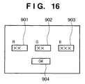
- Fig. 16 shows an example of the color signal input UI used in step S3801.
- This UI is comprised of an R signal input portion 901, G signal input portion 902, B signal input portion 903, and OK button 904.
- the user inputs color signal values for which he/she wants to check estimation errors to the R, G, and B signal input portions 901, 902, and 903.
- the OK button 904 is selected, the input R, G, and B color signal values are stored in the check color signal retention unit 715. The flow then advances to step S3802.
- Fig. 17 shows an example of the final color signal check UI used in step S3802.
- This UI is comprised of an YES button 1001 and NO button 1002. If the YES button 1001 is selected, the flow advances to step S3803. When the NO button 1002 is selected, the flow advances to step S3801 to wait for inputting the next color signal.
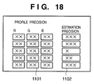
- Fig. 18 shows an example of how estimation errors are displayed in the sixth embodiment.
- sets of color signal values 1101 and estimation errors 1102 are output in correspondence with the number of colors input through the color signal input UI. That is, the color signal value 1101 is the color signal value input in step S3801, and the estimation error 1102 is a colorimetric value estimation error corresponding to the color signal value.
- the profile manager can check an estimation error about a specific color signal and determine the validity of the exiting profile.
- an colorimetric value estimation error based on the exiting profile is output with respect to an arbitrary colorimetric value.
- Fig. 19 shows the arrangement of a profile controller 36 according to the seventh embodiment.
- a characteristic feature of the arrangement shown in Fig. 19 is that it has a check colorimetric value input UI unit 1214 and check color signal retention unit 1215 in addition to the arrangement shown in Fig. 9 in the fourth embodiment.
- the check colorimetric value input UI unit 1214 has a colorimetric value input UI and final colorimetric value check UI, and inputs a check colorimetric value upon user operation.
- the check color signal retention unit 1215 stores estimation error check color signals corresponding to one or a plurality of sets of colorimetric values input through the check colorimetric value input UI unit 1214. Note that the same reference numerals as in Fig. 9 denote the same parts in Fig. 19, and a description thereof will be omitted.
- Fig. 20 is a flow chart showing a procedure for outputting colorimetric value estimation errors in the seventh embodiment.
- the check colorimetric value input UI unit 1214 inputs a check colorimetric value through the colorimetric value input UI (step S3131).
- a color signal corresponding to the input colorimetric value is estimated by using the existing profile stored in a profile retention unit 201 (step S3132). It is then checked whether the input colorimetric value falls within the color reproduction range of an image output apparatus 212 (step S3133). If it falls outside the reproduction range, the corresponding information is notified (displayed), and the flow returns to step S3131. If it falls within the color reproduction range, the flow advances to step S3134 to store the color signal estimated in step S3132 in the check color signal retention unit 1215.
- the check colorimetric value input UI unit 1214 inputs through the final colorimetric value check UI a user instruction indicating whether to continue to input a check colorimetric value (step S3135). If the instruction indicates the continuation of inputting, the flow returns to step S3131. If the instruction indicates the termination of inputting, the flow advances to step S3136.
- color image data for a colorimetric value estimation error check is formed by using the color chips of the color signals stored in the check color signal retention unit 1215 (step S3136), and is stored in a check image retention unit 202 (step S3137).
- step S3301 to S3306 the same processing as that described with reference to Fig. 10 in the fourth embodiment is started (steps S3301 to S3306), and hence a description thereof will be omitted.
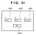
- Fig. 21 shows an example of the colorimetric value input UI used in step S3131 described above.
- This UI is comprised of an L* input portion 1401, a* input portion 1402, b* input portion 1403, and OK button 1404.
- the user inputs colorimetric values for which he/she wants to check estimation errors to the L*, a*, and b* input portions 1401, 1402, and 1403.
- the OK button 1404 is selected, the flow advances to step S3132.
- Fig. 22 shows an example of the final colorimetric value check UI used in step S3135.
- This UI is comprised of a YES button 1501 and NO button 1502.
- the flow advances to step S3136. If NO button 1502 is selected, the flow advances to step S3131 to wait for inputting the next colorimetric value.
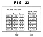
- Fig. 23 shows an example of how estimation errors are displayed in the seventh embodiment.
- sets of colorimetric values 1601 and estimation errors 1602 are output in correspondence with the number of colors input through the colorimetric value input UI. That is, the colorimetric value 1601 is the colorimetric value input in step S3131, and the estimation error 1602 is the color difference between the colorimetric value of the image output on the basis of the estimated value of a color signal corresponding to the colorimetric value and the input colorimetric value.
- the profile manager can check an estimation error about a specific colorimetric value and determine the validity of the existing profile.
- color reproduction variation information in an image input/output apparatus is output in addition to the estimation error based on an existing profile.
- This allows a profile manager to refer to the variation information as well. Hence, the profile manager can determine the validity of the profile more properly.
- Fig. 24 shows the arrangement of a profile controller 36 in the eighth embodiment.
- this arrangement includes a variation information calculation unit 1714 and variation information retention unit 1715 in addition to the arrangement of the fourth embodiment shown in Fig. 9.
- the variation information calculation unit 1714 calculates color reproduction variation information in an output image from an image output apparatus 212, and stores it in the variation information retention unit 1715.
- This variation information is obtained by, for example, making an image output apparatus 212 to output a plurality of color image data having the same value and quantifying variations in colorimetric value in the plurality of output images.
- the same reference numerals as in Fig. 9 denote the same parts in Fig. 24, and a description thereof will be omitted.
- a procedure for outputting colorimetric value estimation errors in the eight embodiment is the same as that in the fourth embodiment described above, and hence follows the flow chart of Fig. 10. According to a characteristic feature of this procedure, however, in the estimation error output processing in step S3306, the variation information stored in the variation information retention unit 1715 is also output to an estimation error output apparatus 213.
- Fig. 25 shows an example of how estimation errors are displayed in the eighth embodiment.
- sets of color names 1801, estimation errors 1802, and pieces of variation information 1803 are output in correspondence with the number of colors. That is, in addition to the data in the estimation error display example in the fifth embodiment (Fig. 13), the colorimetric value variations corresponding to the respective color names are output.
- Fig. 26 is a flow chart showing vibration information acquisition processing in the eighth embodiment.
- the color image data stored in a check image retention unit 202 is output to the image output apparatus 212 through an image output unit 203 to print out images on, for example, 10 printing sheets (step S3191).
- the 10 output images are colorimetrically measured by a colorimetry apparatus 211 (step S3192).
- the colorimetry result is stored in a measurement result retention unit 207 through a colorimetric value input unit 204 (step S3193).
- the variation information calculation unit 1714 then calculates a variation estimation index U on the basis of the 10 colorimetric values stored in the measurement result retention unit 207 (step S3194). This variation estimation index U is stored in the variation information retention unit 1715.
- step S3194 As a method of calculating the variation estimation index U in step S3194, for example, the same method as the procedure shown in Fig. 3 in the first embodiment is used.
- the sampling count for calculating the variation evaluation index U is not limited to 10.
- the profile manager can check the degrees of variations in the colors of an output image from an image output apparatus in addition to estimation errors about colorimetric values based on the existing profile.
- the profile manager therefore can properly determine the validity of the profile in consideration of variation information.
- the CIE/L*a*b* color space is used as a device-independent color space.
- the CIE/XYZ or CIE/L*u*v* color space or another color spaced based on these color space may be used.
- an evaluation value (estimation error) of a profile is calculated by using the CIE1994 color difference formula.
- the CIE1976 color difference formula, CMC color difference formula, BFD color difference formula, BLAB color difference formula, or another evaluation value for quantifying the difference between a pair of color signals may be used.
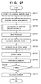
- Fig. 27 is a flow chart showing a procedure for obtaining the relationship between a color signal and a device-independent color space to create a profile for a CMS in this embodiment.
- an image whose entire surface is formed by uniform color signals is output (step S2101).
- Color variations are measured by performing colorimetry at a plurality of points in the output image (step S2102).
- a variation estimation index U is then calculated on the basis of the measurement values (step S2103). Note that the index U is calculated by the method shown in Fig. 3 in the first embodiment.
- a desired precision (confidence interval) S is input (step S2104).
- the sampling count n required to obtain an average value with this precision S is obtained by equation (12) (step S2105).
- n (2.58U/S) 2
- An image (color patch image) in which colors necessary for the creation of a profile are arranged is generated (step S2106).
- This image is then output to perform colorimetry (steps S2107 and S2108).
- the processing in steps S2107 to S2108 is repeated a total of n times (S2109).
- the obtained n measurement values are averaged (step S2110), and the average value is set as a value in a device-independent color space which corresponds to a color signal. Note that instead of the average value of the n measurement values, the median of the measurement values may be effectively used as a value in the device-independent color space.
- a profile can be created as a transformation formula or table for transforming the color signals and the values in a device-independent color space.
- Fig. 28 shows an example of the color arrangement of the color patch image generated in step S2106 in Fig. 27.
- patches of the same color are dispersed in a plane of an output image form the output apparatus 5 to average color reproduction characteristic variations within the plane.
- each number is a color number indicating a color type. More specifically, 300 colors (numbers 1 to 300 in Fig. 28) are arranged in one image, and four images obtained by shifting these colors are output. The four images are colorimetrically measured, and the respective colors are averaged. In the ninth embodiment, therefore, a profile for a CMS is created on the basis of combinations of the 300 color signals and the averages of the four corresponding measurement values.
- a profile for a CMS can be created in consideration of in-plane variations in an output image from the output apparatus 5.
- color reproduction can be implemented while the influence of the in-plane variations in the output apparatus 5 is suppressed.
- the ninth embodiment has exemplified the case wherein the values obtained by measuring identical colors in four images are averaged. Obviously, however, a similar effect can be obtained by arranging identical colors at a plurality of positions on one image.
- the ninth embodiment has exemplified the creation processing for the profile 35 associated with the output apparatus 5, the present invention can be applied to the input apparatus 1 as well. That is, in the ninth embodiment, the processing based on variations in colorimetric value in a sample image output from the output apparatus 5 has been described. However, by giving consideration to variations in signal value in a sample image input by the input apparatus 1 instead of the above variations, the profile 34 can be properly created in the input apparatus 1 in the same manner as described above. This technique is especially effective when the input apparatus 1 is a scanner for reading images.
- the 10th embodiment according to the present invention will be described below.
- the arrangement of an image processing apparatus in the 10th embodiment is the same as that shown in Fig. 1 in the first embodiment described above, and hence a description thereof will be omitted.
- a proper profile can be created while the influence of immediately preceding image output processing in the output apparatus 5 is suppressed.
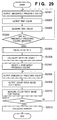
- Fig. 29 is a flow chart showing a procedure for obtaining the relationship between color signals and an device-independent color space to create a profile for a CMS in the 10th embodiment.
- a set of color signals sampled at proper intervals as immediately preceding output colors from the output apparatus 5 will be referred to as an immediately preceding color group hereinafter.
- a sampling count n for obtaining an average colorimetric value is obtained.
- n sampled values obtained by colorimetry after n immediately preceding colors are output are averaged to obtain a colorimetric value with the influence of the immediately preceding colors being suppressed.
- one of an immediately preceding color group constituted by a plurality of color signals sampled at proper intervals is output from the output apparatus 5 (step S2301). Subsequently, a full-surface uniform image formed by a specific color signal (test color) is output (step S2302), and colorimetrically measured (step S2303).
- the processing in steps S2301 to S2303 is repeated for all immediately preceding colors in the immediately preceding color group (step S2304). With this operation, colorimetric values corresponding to all the immediately preceding colors can be obtained.
- the output apparatus 5 outputs a white (225, 255, 255) image, and then outputs an image of a test color to perform colorimetry. Subsequently, the output apparatus 5 outputs a black (0, 0, 0) image, and then outputs an image of a test color to perform colorimetry.
- a variation evaluation index U is obtained on the basis of the colorimetric values of test colors, which are obtained for the respective immediately preceding colors, by the same procedure as that shown in Fig. 3 in the first embodiment (step S2305).
- a sampling count n required to obtain an average value with a desired precision S is obtained on the basis of equation (12) in the ninth embodiment (step S2306).
- n immediately preceding colors are selected by sampling color signals at equal intervals (step S2307).
- a color patch image required for the creation of a profile is output (step S2309).
- This image is then colorimetrically measured (step S2310).
- This processing in steps S2308 to S2310 is repeated for n immediately preceding colors (step S2311). With this operation, n colorimetric values of the respective color signals used for the creation of a profile can be obtained with respect to different immediately preceding colors.
- step S2312 The n colorimetric values obtained for each color in the color patch image are averaged (step S2312), and the average value is set as a color in the device-independent color space corresponding to the color signal.
- a profile can be created as a transformation formula or table for transforming the two values.
- a profile for a CMS can be created in consideration of the influence of an immediately preceding image output from the output apparatus 5.
- color reproduction can be implemented while the influence of an immediately preceding image output from the output apparatus 5 is suppressed.
- the 10th embodiment has exemplified the creation of a profile with the influence of an immediately preceding image output from the output apparatus 5 being suppressed
- the 10th embodiment may be so modified as to suppress the influence of each immediately preceding color in one output image in which a plurality of colors are arranged.
- the 11th embodiment of the present invention will be described below.
- the arrangement of an image processing apparatus in the 11th embodiment is the same as that in the first embodiment in Fig. 1, a description thereof will be omitted.
- an average color difference is used in place of the variation evaluation index U in step S2103 in Fig. 27 in the ninth embodiment.
- Fig. 30 is a flow chart showing a procedure for calculating an average color difference in the 11th embodiment.
- average coordinates (L* ave , a* ave , b* ave ) in the CIE/L*a*b* space are obtained on the basis of the colorimetric values of output images based on identical color signals according to equations (1) (step S2401).
- a color difference ⁇ E between the average coordinates and each colorimetric value is calculated according to equation (13) given below (step S2402).
- ⁇ E ⁇ (L* ave -L*) 2 +(a* ave -a*) 2 +(b* ave -b*) 2
- the color differences ⁇ E of the respective colorimetric values are averaged (step S2403), and the average value is used in place of the variation evaluation index U in the ninth embodiment.
- a proper profile for a CMS can be created in consideration of the influence of an immediately preceding image output from an output apparatus 5 as in the ninth embodiment, thus realizing proper color reproduction.
- the CIE1976 color difference formula is used in step S2402 in the 11th embodiment.
- the present invention is not limited to this.
- another color difference formula such as the CIE1994, CMC, BFD, or MLAB color difference formula can be used.
- the present invention may be applied to a system constituted by a plurality of devices (e.g., a host computer, an interface device, a reader, a printer, and the like) or an apparatus comprising a single device (e.g., a copying machine, a facsimile apparatus, or the like) .
- a plurality of devices e.g., a host computer, an interface device, a reader, a printer, and the like
- an apparatus comprising a single device e.g., a copying machine, a facsimile apparatus, or the like
- the object of the present invention is realized even by supplying a storage medium storing software program codes for realizing the functions of the above-described embodiments to a system or apparatus, and causing the computer (or a CPU or an MPU) of the system or apparatus to read out and execute the program codes stored in the storage medium.
- the program codes read out from the storage medium realize the functions of the above-described embodiments by themselves, and the storage medium storing the program codes constitutes the present invention.
- a storage medium for supplying the program codes a floppy disk, a hard disk, an optical disk, a magnetooptical disk, a CD-ROM, a CD-R, a magnetic tape, a nonvolatile memory card, a ROM, or the like can be used.
- the functions of the above-described embodiments are realized not only when the readout program codes are executed by the computer but also when the OS (Operating System) running on the computer performs part or all of actual processing on the basis of the instructions of the program codes.
- OS Operating System
Landscapes
- Physics & Mathematics (AREA)
- General Physics & Mathematics (AREA)
- Engineering & Computer Science (AREA)
- Theoretical Computer Science (AREA)
- Facsimile Image Signal Circuits (AREA)
- Color Image Communication Systems (AREA)
- Image Processing (AREA)
Abstract
Description



Claims (37)
- A method of controlling an image processing apparatus for performing color transformation based on color transformation information unique to a connected device, characterized by comprising:a first acquisition step of acquiring a current characteristic representing a current color reproduction characteristic of the device;a second acquisition step of acquiring an estimated characteristic representing a color reproduction characteristic based on the color transformation information of the device;a third acquisition step of acquiring a degree of stability of a color reproduction characteristic in the device; anda determination step of determining, on the basis of the current characteristic, the estimated characteristic, and the degree of stability, whether the color transformation information properly reflects the current characteristic.
- The method according to claim 1, characterized in that in the determination step, if a difference between the current characteristic and the estimated characteristic is significant in terms of the degree of stability, it is determined that the color transformation information does not reflect the color reproduction characteristic.
- The method according to claim 2, characterized in that in the determination step, it is determined, on the basis of a t-statistic corresponding to the degree of stability of the difference, whether the difference is significant.
- The method according to claim 1, characterized in that the degree of stability is a variation degree of colorimetric value of sample images reproduced by the device.
- The method according to claim 1, characterized by further comprising the update step of updating the color transformation information.
- The method according to claim 1, characterized by further comprising the notification step of notifying a user when it is determined in the determination step that the color transformation information does not reflect the current characteristic.
- The method according to claim 1, characterized in thatthe image processing apparatus retains additional information at the time of creation of the color transformation information in retention means, andin the determination step, it is determined on the basis of the additional information whether the color transformation information reflects the current color reproduction characteristic.
- The method according to claim 7, characterized in that the additional information includes at least one of a sampling count by which a sample image is colorimetrically measured at the time of creation of the color transformation information, an average colorimetric value of the sample image, and a root sum square of color differences.
- The method according to claim 7, characterized in that the additional information includes a degree of stability of the device at the time of creation of the color transformation information.
- The method according to any one of claims 1 to 14, characterized in that the color transformation information is a color transformation profile which is referred to in order to perform color space transformation corresponding to a characteristic of the device.
- An image processing apparatus for performing color transformation based on color transformation information unique to a connected device, characterized by comprising:first acquisition means for acquiring a current characteristic representing a current color reproduction characteristic of the device;second acquisition means for acquiring an estimated characteristic representing a color reproduction characteristic based on the color transformation information of the device;third acquisition means for acquiring a degree of stability of a color reproduction characteristic in the device;determination means for determining, on the basis of the current characteristic, the estimated characteristic, and the degree of stability, whether the color transformation information properly reflects the current characteristic; andupdate means for updating the color transformation information on the basis of the determination result.
- A control program for an image processing apparatus for performing color transformation based on color transformation information unique to a connected device, characterized by comprising:code for a first acquisition step of acquiring a current characteristic representing a current color reproduction characteristic of the device;code for a second acquisition step of acquiring an estimated characteristic representing a color reproduction characteristic based on the color transformation information of the device;code for a third acquisition step of acquiring a degree of stability of a color reproduction characteristic in the device; andcode for a determination step of determining, on the basis of the current characteristic, the estimated characteristic, and the degree of stability, whether the color transformation information properly reflects the current characteristic.
- A recording medium characterized in that the program defined in claim 12 is recorded on the medium.
- A method of controlling an image processing apparatus for performing color transformation based on color transformation information unique to a connected device, characterized by comprising:a first acquisition step of acquiring a current characteristic representing a current color reproduction characteristic of the device;a second acquisition step of acquiring an estimated characteristic representing a color reproduction characteristic based on the color transformation information of the device; anda evaluation step of evaluating a degree of reflection of the current characteristic in the color transformation information on the basis of the current characteristic and the estimated characteristic.
- The method according to claim 14, characterized in that in the evaluation step, a difference between the current characteristic and the estimated characteristic is calculated as the degree of reflection.
- The method according to claim 14, characterized in that in the first acquisition step, the current characteristic is calculated on the basis of a colorimetry result of a sample image reproduced by the device, and in the second acquisition step, an estimated output color, with respect to a color signal of the sample image, which is obtained on the basis of the color transformation information is acquired as the estimated characteristic.
- The method according to claim 14, characterized by further comprising the notification step of notifying a user of an evaluation result in the evaluation step.
- The method according to claim 17, characterized by further comprising the update step of updating the color transformation information on the basis of a user instruction corresponding to the notification to the user.
- The method according to claim 16, characterized in that the sample image is formed by a color signal designated by the user.
- The method according to claim 17, characterized in that the method further comprises the third acquisition step of acquiring a degree of stability of a current color reproduction characteristic in the device, andin the notification step, the user is notified of the degree of stability, together with the evaluation result.
- The method according to claim 20, characterized in that the degree of stability is a variation degree of the colorimetric value.
- An image processing apparatus for performing color transformation based on color transformation information unique to a connected device, characterized by comprising:first acquisition means for acquiring a current characteristic representing a current color reproduction characteristic of the device;second acquisition means for acquiring an estimated characteristic representing a color reproduction characteristic based on the color transformation information of the device; andevaluation means for evaluating the degree of reflection of the color transformation information on the current characteristic on the basis of the current characteristic and the estimated characteristic.
- A control program for an image processing apparatus for performing color transformation based on color transformation information unique to a connected device, characterized by comprising:code for a first acquisition step of acquiring a current characteristic representing a current color reproduction characteristic of the device;code for a second acquisition step of acquiring an estimated characteristic representing a color reproduction characteristic based on the color transformation information of the device; andcode for a evaluation step of evaluating the degree of reflection of the color transformation information on the current characteristic on the basis of the current characteristic and the estimated characteristic
- A recording medium characterized in that the program defined in claim 22 is recorded on the medium.
- A method of controlling an image processing apparatus for performing color transformation based on color transformation information unique to a connected device, characterized by comprising:a stability degree acquisition step of acquiring a degree of stability of a color reproduction characteristic in the device;a representative value acquisition step of acquiring a representative value of color reproduction in the device on the basis of the degree of stability; anda color transformation information generation step of generating color transformation information unique to the device on the basis of the representative value.
- The method according to claim 25, characterized in that the degree of stability is an in-plane variation in color reproduction characteristic in the device.
- The method according to claim 26, characterized in that the degree of stability is a variation degree of colorimetric values at a plurality of positions in an image formed by a uniform color signal reproduced in the device.
- The method according to claim 27, characterized in that in the stability degree acquisition step, the variation degree is calculated by applying the CIE1994 color difference formula to a standard deviation of the colorimetric values.
- The method according to claim 28, characterized in that in the stability degree acquisition step, the standard deviation of the colorimetric values is obtained for each of lightness, chroma, and hue.
- The method according to claim 27, characterized in that in the stability acquisition step, the variation degree is calculated on the basis of a measured luminance and an average value of color differences.
- The method according to claim 25, characterized in that in the representative value acquisition step, a sampling count for calculating the representative value is determined on the basis of the degree of stability, and the representative value is calculated with respect to a test image formed by a plurality of color signals reproduced in the device on the basis of colorimetric values corresponding to the sampling count for each color.
- An image processing apparatus for performing color transformation based on color transformation information unique to a connected device, characterized by comprising:stability degree acquisition means for acquiring a degree of stability of a color reproduction characteristic in the device;representative value acquisition means for acquiring a representative value of color reproduction in the device on the basis of the degree of stability; andcolor transformation information generation means for generating color transformation information unique to the device on the basis of the representative value.
- An image processing system for transforming an image signal in a first color space which is input from an image input device into an image signal in a second color space on the basis of predetermined color transformation information, and outputting the signal from an image output device, characterized by comprising:stability degree acquisition means for acquiring a stability degree characteristic indicating a degree of stability of color reproduction characteristic in one of the devices;representative value acquisition means for acquiring a representative value of color reproduction in the device on the basis of the stability degree characteristic; andcolor transformation information generation means for generating the color transformation information on the basis of the representative value.
- The system according to claim 33, characterized in that the color transformation information includes first color transformation information about the image input device and second color transformation information about the image output device.
- The system according to claim 34, characterized in that after a signal in the first color space is transformed into a signal in a predetermined common color space on the basis of the first color transformation information, the signal is further transformed into a signal in a second color space on the basis of the second color transformation information.
- A control program for performing color transformation based on color transformation information unique to a connected device, characterized by comprising:code for a stability degree acquisition step of acquiring a stability degree characteristic indicating a degree of stability of color reproduction characteristic in the device;code for a representative value acquisition step of acquiring a representative value of color reproduction in the device on the basis of the stability degree characteristic; andcode for a color transformation information generation step of generating color transformation information unique to the device on the basis of the representative value.
- A recording medium characterized in that the program defined in claim 36 is recorded on the medium.
Applications Claiming Priority (6)
| Application Number | Priority Date | Filing Date | Title |
|---|---|---|---|
| JP2000219568 | 2000-07-19 | ||
| JP2000219567 | 2000-07-19 | ||
| JP2000219567A JP3715871B2 (en) | 2000-07-19 | 2000-07-19 | Color processing apparatus and method |
| JP2000219568 | 2000-07-19 | ||
| JP2001214193 | 2001-07-13 | ||
| JP2001214193A JP3762260B2 (en) | 2000-07-19 | 2001-07-13 | Color processing method and apparatus |
Publications (2)
| Publication Number | Publication Date |
|---|---|
| EP1174827A2 true EP1174827A2 (en) | 2002-01-23 |
| EP1174827A3 EP1174827A3 (en) | 2004-01-21 |
Family
ID=27344120
Family Applications (1)
| Application Number | Title | Priority Date | Filing Date |
|---|---|---|---|
| EP01306199A Withdrawn EP1174827A3 (en) | 2000-07-19 | 2001-07-19 | Image processing apparatus and control method therefor |
Country Status (2)
| Country | Link |
|---|---|
| US (1) | US7003151B2 (en) |
| EP (1) | EP1174827A3 (en) |
Cited By (1)
| Publication number | Priority date | Publication date | Assignee | Title |
|---|---|---|---|---|
| WO2005032151A1 (en) * | 2003-09-30 | 2005-04-07 | Koninklijke Philips Electronics, N.V. | Universal color decoder and method for decoding input signal for a multiple primary color display system |
Families Citing this family (23)
| Publication number | Priority date | Publication date | Assignee | Title |
|---|---|---|---|---|
| JP2002187314A (en) * | 2000-09-12 | 2002-07-02 | Canon Inc | Image processing apparatus and method, prediction method, display method, and management method |
| US6831999B2 (en) * | 2001-02-08 | 2004-12-14 | Canon Kabushiki Kaisha | Color management architecture using phantom profiles to transfer data between transformation modules |
| DE60229338D1 (en) * | 2001-09-07 | 2008-11-27 | Canon Kk | Image processing method and apparatus |
| JP2004015547A (en) * | 2002-06-07 | 2004-01-15 | Canon Inc | Image encryption device, image encryption method, decryption device, decryption method, program, storage medium |
| JP2004135312A (en) * | 2002-09-20 | 2004-04-30 | Ricoh Co Ltd | Image processing apparatus, image processing system, image forming apparatus, image processing method, and program |
| US7385728B2 (en) * | 2002-10-03 | 2008-06-10 | Hewlett-Packard Development Company, L.P. | Systems and methods for optimizing printing |
| JP2004291278A (en) * | 2003-03-25 | 2004-10-21 | Dainippon Screen Mfg Co Ltd | Color management method and system in plate-making printing system |
| JP2005117097A (en) * | 2003-10-02 | 2005-04-28 | Seiko Epson Corp | Profile creation apparatus, profile creation method, and profile creation program |
| US7599551B2 (en) * | 2003-11-14 | 2009-10-06 | Mitsubishi Denki Kabushiki Kaisha | Color correction device and color correction method |
| JP4401955B2 (en) * | 2004-03-03 | 2010-01-20 | キヤノン株式会社 | Color processing apparatus and method |
| US7453602B2 (en) * | 2004-06-01 | 2008-11-18 | Canon Kabushiki Kaisha | Color conversion method |
| JP4393294B2 (en) * | 2004-07-07 | 2010-01-06 | キヤノン株式会社 | Image processing apparatus and method |
| JP4624248B2 (en) * | 2005-12-06 | 2011-02-02 | 富士フイルム株式会社 | Image processing apparatus, skin color adjustment method, and program |
| JP4802991B2 (en) * | 2006-11-14 | 2011-10-26 | 富士ゼロックス株式会社 | Color processing apparatus, color processing method, and program |
| US20080144114A1 (en) * | 2006-12-18 | 2008-06-19 | Xerox Corporation | Method and system for dynamic printer profiling |
| JP2009194553A (en) * | 2008-02-13 | 2009-08-27 | Seiko Epson Corp | How to determine the number of patches |
| JP5132428B2 (en) * | 2008-05-28 | 2013-01-30 | キヤノン株式会社 | Information processing apparatus, method, and program |
| US8376502B2 (en) | 2009-03-25 | 2013-02-19 | Canon Kabushiki Kaisha | Method and apparatus for generating color separation table, and image forming apparatus |
| US20110216334A1 (en) * | 2010-03-04 | 2011-09-08 | Kabushiki Kaisha Toshiba | Image processing device, image forming apparatus and image processing method |
| JP5649337B2 (en) * | 2010-06-02 | 2015-01-07 | キヤノン株式会社 | Profile processing apparatus, profile processing method and program |
| JP5843503B2 (en) | 2010-08-20 | 2016-01-13 | キヤノン株式会社 | Image recording system and image recording method |
| JP6018418B2 (en) | 2012-05-31 | 2016-11-02 | キヤノン株式会社 | Image recording apparatus and image recording method |
| US8934155B2 (en) * | 2013-03-01 | 2015-01-13 | Xerox Corporation | Standardized multi-intent color control architecture |
Family Cites Families (17)
| Publication number | Priority date | Publication date | Assignee | Title |
|---|---|---|---|---|
| US4710785A (en) * | 1986-12-12 | 1987-12-01 | Eastman Kodak Company | Process control for electrostatographic machine |
| US6081254A (en) * | 1993-08-12 | 2000-06-27 | Hitachi, Ltd. | Color correction system of imaging apparatus |
| US5416613A (en) * | 1993-10-29 | 1995-05-16 | Xerox Corporation | Color printer calibration test pattern |
| JP3083067B2 (en) * | 1994-08-03 | 2000-09-04 | 富士ゼロックス株式会社 | Method and apparatus for determining color conversion coefficient |
| US5881209A (en) * | 1994-09-13 | 1999-03-09 | Apple Computer, Inc. | Method and system for automatically generating printer profiles |
| US5856876A (en) * | 1995-04-06 | 1999-01-05 | Canon Kabushiki Kaisha | Image processing apparatus and method with gradation characteristic adjustment |
| JPH08289149A (en) | 1995-04-10 | 1996-11-01 | Canon Inc | Image recording apparatus and method |
| US5781206A (en) | 1995-05-01 | 1998-07-14 | Minnesota Mining And Manufacturing Company | Apparatus and method for recalibrating a multi-color imaging system |
| US6459425B1 (en) * | 1997-08-25 | 2002-10-01 | Richard A. Holub | System for automatic color calibration |
| JP3771633B2 (en) * | 1996-07-17 | 2006-04-26 | 富士写真フイルム株式会社 | Color correction device |
| KR100240070B1 (en) | 1997-07-10 | 2000-01-15 | Samsung Electronics Co Ltd | Apparatus and method for color calibration in image system |
| US6697660B1 (en) * | 1998-01-23 | 2004-02-24 | Ctf Systems, Inc. | Method for functional brain imaging from magnetoencephalographic data by estimation of source signal-to-noise ratio |
| JP2000196906A (en) * | 1998-10-22 | 2000-07-14 | Xerox Corp | System and method for printing |
| US6650771B1 (en) * | 1999-11-22 | 2003-11-18 | Eastman Kodak Company | Color management system incorporating parameter control channels |
| US20020122589A1 (en) * | 1999-11-29 | 2002-09-05 | Donald M. Reiman | Constructing profiles to compensate for non-linearities in image capture |
| US6809837B1 (en) * | 1999-11-29 | 2004-10-26 | Xerox Corporation | On-line model prediction and calibration system for a dynamically varying color reproduction device |
| US6525721B1 (en) * | 2000-05-05 | 2003-02-25 | Xerox Corporation | Color profile management and color collection management, navigation and visual design |
-
2001
- 2001-07-18 US US09/906,644 patent/US7003151B2/en not_active Expired - Lifetime
- 2001-07-19 EP EP01306199A patent/EP1174827A3/en not_active Withdrawn
Cited By (1)
| Publication number | Priority date | Publication date | Assignee | Title |
|---|---|---|---|---|
| WO2005032151A1 (en) * | 2003-09-30 | 2005-04-07 | Koninklijke Philips Electronics, N.V. | Universal color decoder and method for decoding input signal for a multiple primary color display system |
Also Published As
| Publication number | Publication date |
|---|---|
| EP1174827A3 (en) | 2004-01-21 |
| US7003151B2 (en) | 2006-02-21 |
| US20020039106A1 (en) | 2002-04-04 |
Similar Documents
| Publication | Publication Date | Title |
|---|---|---|
| EP1174827A2 (en) | Image processing apparatus and control method therefor | |
| US20120032973A1 (en) | Image processing apparatus, image processing method, and storage medium | |
| EP1294177A2 (en) | Image processing method and apparatus | |
| EP4661390A1 (en) | Parameter measurement method and apparatus, electronic device, and computer storage medium | |
| JP2002187314A (en) | Image processing apparatus and method, prediction method, display method, and management method | |
| Cheng et al. | Assessing color performance of whole‐slide imaging scanners for digital pathology | |
| JP2000184223A (en) | Calibration method for scanner, image forming device and calibration processor | |
| Felicísimo et al. | Measurement and control of colour fidelity in scanned 3D models for heritage conservation | |
| EP1854277B1 (en) | Reflectance spectra estimation and colour space conversion using reference reflectance spectra | |
| JP2001324413A (en) | Method and device for measuring mtf | |
| JP5474113B2 (en) | Image processing apparatus and image processing method | |
| Farrell et al. | Estimating spectral reflectances of digital artwork | |
| JP2002094820A (en) | Image processing apparatus and method | |
| EP3605467B1 (en) | Coating color identifying device, coating color identifying method, coating color identifying program, and computer-readable medium containing coating color identifying program | |
| JP2009225479A (en) | Image processor, image processing method, and program | |
| Stokes | Colorimetric tolerances of digital images | |
| WO2004012442A1 (en) | Image processing system, apparatus, and method, and color reproduction method | |
| US8213051B2 (en) | Color management workflow for transitioning offset printing using custom inks to digital printing | |
| US9293113B2 (en) | Image processing apparatus and control method thereof | |
| JP3762260B2 (en) | Color processing method and apparatus | |
| Kerouh et al. | Content-based computational chromatic adaptation | |
| US20020018128A1 (en) | System and method for analyzing, optimizing and/or designing spectral sensitivity curves for an imaging device | |
| US9927630B2 (en) | Color calibration for pathology slides | |
| JP4066334B2 (en) | Video signal processing device | |
| JPH11313216A (en) | Image processing method, apparatus and recording medium |
Legal Events
| Date | Code | Title | Description |
|---|---|---|---|
| PUAI | Public reference made under article 153(3) epc to a published international application that has entered the european phase |
Free format text: ORIGINAL CODE: 0009012 |
|
| AK | Designated contracting states |
Kind code of ref document: A2 Designated state(s): AT BE CH CY DE DK ES FI FR GB GR IE IT LI LU MC NL PT SE TR |
|
| AX | Request for extension of the european patent |
Free format text: AL;LT;LV;MK;RO;SI |
|
| PUAL | Search report despatched |
Free format text: ORIGINAL CODE: 0009013 |
|
| AK | Designated contracting states |
Kind code of ref document: A3 Designated state(s): AT BE CH CY DE DK ES FI FR GB GR IE IT LI LU MC NL PT SE TR |
|
| AX | Request for extension of the european patent |
Extension state: AL LT LV MK RO SI |
|
| RIC1 | Information provided on ipc code assigned before grant |
Ipc: 7H 04N 1/60 B Ipc: 7G 06T 11/00 A |
|
| 17P | Request for examination filed |
Effective date: 20040611 |
|
| AKX | Designation fees paid |
Designated state(s): DE ES FR GB IT NL |
|
| 17Q | First examination report despatched |
Effective date: 20041103 |
|
| STAA | Information on the status of an ep patent application or granted ep patent |
Free format text: STATUS: THE APPLICATION HAS BEEN WITHDRAWN |
|
| 18W | Application withdrawn |
Effective date: 20160218 |