EP1174625B1 - Dosierventilanordnung zum Speisen eines gasförmigen Mediums in ein in einem Kraftfahrzeug eingesetztes Brennstoffzellen-System - Google Patents
Dosierventilanordnung zum Speisen eines gasförmigen Mediums in ein in einem Kraftfahrzeug eingesetztes Brennstoffzellen-System Download PDFInfo
- Publication number
- EP1174625B1 EP1174625B1 EP01117427A EP01117427A EP1174625B1 EP 1174625 B1 EP1174625 B1 EP 1174625B1 EP 01117427 A EP01117427 A EP 01117427A EP 01117427 A EP01117427 A EP 01117427A EP 1174625 B1 EP1174625 B1 EP 1174625B1
- Authority
- EP
- European Patent Office
- Prior art keywords
- fuel cell
- cell system
- metering valves
- center block
- valves
- Prior art date
- Legal status (The legal status is an assumption and is not a legal conclusion. Google has not performed a legal analysis and makes no representation as to the accuracy of the status listed.)
- Expired - Lifetime
Links
- 239000000446 fuel Substances 0.000 title claims description 38
- 230000015572 biosynthetic process Effects 0.000 claims description 5
- 238000005755 formation reaction Methods 0.000 claims description 5
- 238000007789 sealing Methods 0.000 claims 1
- 239000007789 gas Substances 0.000 description 7
- UFHFLCQGNIYNRP-UHFFFAOYSA-N Hydrogen Chemical compound [H][H] UFHFLCQGNIYNRP-UHFFFAOYSA-N 0.000 description 3
- 238000004806 packaging method and process Methods 0.000 description 3
- QVGXLLKOCUKJST-UHFFFAOYSA-N atomic oxygen Chemical compound [O] QVGXLLKOCUKJST-UHFFFAOYSA-N 0.000 description 2
- 238000010276 construction Methods 0.000 description 2
- 239000001257 hydrogen Substances 0.000 description 2
- 229910052739 hydrogen Inorganic materials 0.000 description 2
- 238000005259 measurement Methods 0.000 description 2
- 238000000034 method Methods 0.000 description 2
- 239000001301 oxygen Substances 0.000 description 2
- 229910052760 oxygen Inorganic materials 0.000 description 2
- 239000004215 Carbon black (E152) Substances 0.000 description 1
- 239000012141 concentrate Substances 0.000 description 1
- 230000001419 dependent effect Effects 0.000 description 1
- 230000000694 effects Effects 0.000 description 1
- 230000002349 favourable effect Effects 0.000 description 1
- 229930195733 hydrocarbon Natural products 0.000 description 1
- 150000002430 hydrocarbons Chemical class 0.000 description 1
- 238000009434 installation Methods 0.000 description 1
- 230000003993 interaction Effects 0.000 description 1
- 238000012423 maintenance Methods 0.000 description 1
- 239000000463 material Substances 0.000 description 1
- 230000003647 oxidation Effects 0.000 description 1
- 238000007254 oxidation reaction Methods 0.000 description 1
- 238000002407 reforming Methods 0.000 description 1
- 230000001105 regulatory effect Effects 0.000 description 1
- 239000000126 substance Substances 0.000 description 1
Images


Classifications
-
- F—MECHANICAL ENGINEERING; LIGHTING; HEATING; WEAPONS; BLASTING
- F15—FLUID-PRESSURE ACTUATORS; HYDRAULICS OR PNEUMATICS IN GENERAL
- F15B—SYSTEMS ACTING BY MEANS OF FLUIDS IN GENERAL; FLUID-PRESSURE ACTUATORS, e.g. SERVOMOTORS; DETAILS OF FLUID-PRESSURE SYSTEMS, NOT OTHERWISE PROVIDED FOR
- F15B13/00—Details of servomotor systems ; Valves for servomotor systems
- F15B13/02—Fluid distribution or supply devices characterised by their adaptation to the control of servomotors
- F15B13/06—Fluid distribution or supply devices characterised by their adaptation to the control of servomotors for use with two or more servomotors
- F15B13/08—Assemblies of units, each for the control of a single servomotor only
- F15B13/0803—Modular units
- F15B13/0807—Manifolds
- F15B13/0814—Monoblock manifolds
-
- F—MECHANICAL ENGINEERING; LIGHTING; HEATING; WEAPONS; BLASTING
- F15—FLUID-PRESSURE ACTUATORS; HYDRAULICS OR PNEUMATICS IN GENERAL
- F15B—SYSTEMS ACTING BY MEANS OF FLUIDS IN GENERAL; FLUID-PRESSURE ACTUATORS, e.g. SERVOMOTORS; DETAILS OF FLUID-PRESSURE SYSTEMS, NOT OTHERWISE PROVIDED FOR
- F15B13/00—Details of servomotor systems ; Valves for servomotor systems
- F15B13/02—Fluid distribution or supply devices characterised by their adaptation to the control of servomotors
- F15B13/06—Fluid distribution or supply devices characterised by their adaptation to the control of servomotors for use with two or more servomotors
- F15B13/08—Assemblies of units, each for the control of a single servomotor only
- F15B13/0803—Modular units
- F15B13/0821—Attachment or sealing of modular units to each other
-
- F—MECHANICAL ENGINEERING; LIGHTING; HEATING; WEAPONS; BLASTING
- F15—FLUID-PRESSURE ACTUATORS; HYDRAULICS OR PNEUMATICS IN GENERAL
- F15B—SYSTEMS ACTING BY MEANS OF FLUIDS IN GENERAL; FLUID-PRESSURE ACTUATORS, e.g. SERVOMOTORS; DETAILS OF FLUID-PRESSURE SYSTEMS, NOT OTHERWISE PROVIDED FOR
- F15B13/00—Details of servomotor systems ; Valves for servomotor systems
- F15B13/02—Fluid distribution or supply devices characterised by their adaptation to the control of servomotors
- F15B13/06—Fluid distribution or supply devices characterised by their adaptation to the control of servomotors for use with two or more servomotors
- F15B13/08—Assemblies of units, each for the control of a single servomotor only
- F15B13/0803—Modular units
- F15B13/0832—Modular valves
- F15B13/0835—Cartridge type valves
-
- F—MECHANICAL ENGINEERING; LIGHTING; HEATING; WEAPONS; BLASTING
- F15—FLUID-PRESSURE ACTUATORS; HYDRAULICS OR PNEUMATICS IN GENERAL
- F15B—SYSTEMS ACTING BY MEANS OF FLUIDS IN GENERAL; FLUID-PRESSURE ACTUATORS, e.g. SERVOMOTORS; DETAILS OF FLUID-PRESSURE SYSTEMS, NOT OTHERWISE PROVIDED FOR
- F15B13/00—Details of servomotor systems ; Valves for servomotor systems
- F15B13/02—Fluid distribution or supply devices characterised by their adaptation to the control of servomotors
- F15B13/06—Fluid distribution or supply devices characterised by their adaptation to the control of servomotors for use with two or more servomotors
- F15B13/08—Assemblies of units, each for the control of a single servomotor only
- F15B13/0803—Modular units
- F15B13/0846—Electrical details
- F15B13/0857—Electrical connecting means, e.g. plugs, sockets
-
- F—MECHANICAL ENGINEERING; LIGHTING; HEATING; WEAPONS; BLASTING
- F15—FLUID-PRESSURE ACTUATORS; HYDRAULICS OR PNEUMATICS IN GENERAL
- F15B—SYSTEMS ACTING BY MEANS OF FLUIDS IN GENERAL; FLUID-PRESSURE ACTUATORS, e.g. SERVOMOTORS; DETAILS OF FLUID-PRESSURE SYSTEMS, NOT OTHERWISE PROVIDED FOR
- F15B13/00—Details of servomotor systems ; Valves for servomotor systems
- F15B13/02—Fluid distribution or supply devices characterised by their adaptation to the control of servomotors
- F15B13/06—Fluid distribution or supply devices characterised by their adaptation to the control of servomotors for use with two or more servomotors
- F15B13/08—Assemblies of units, each for the control of a single servomotor only
- F15B13/0803—Modular units
- F15B13/0846—Electrical details
- F15B13/086—Sensing means, e.g. pressure sensors
-
- F—MECHANICAL ENGINEERING; LIGHTING; HEATING; WEAPONS; BLASTING
- F15—FLUID-PRESSURE ACTUATORS; HYDRAULICS OR PNEUMATICS IN GENERAL
- F15B—SYSTEMS ACTING BY MEANS OF FLUIDS IN GENERAL; FLUID-PRESSURE ACTUATORS, e.g. SERVOMOTORS; DETAILS OF FLUID-PRESSURE SYSTEMS, NOT OTHERWISE PROVIDED FOR
- F15B13/00—Details of servomotor systems ; Valves for servomotor systems
- F15B13/02—Fluid distribution or supply devices characterised by their adaptation to the control of servomotors
- F15B13/06—Fluid distribution or supply devices characterised by their adaptation to the control of servomotors for use with two or more servomotors
- F15B13/08—Assemblies of units, each for the control of a single servomotor only
- F15B13/0803—Modular units
- F15B13/0878—Assembly of modular units
- F15B13/0882—Assembly of modular units using identical modular elements
-
- F—MECHANICAL ENGINEERING; LIGHTING; HEATING; WEAPONS; BLASTING
- F16—ENGINEERING ELEMENTS AND UNITS; GENERAL MEASURES FOR PRODUCING AND MAINTAINING EFFECTIVE FUNCTIONING OF MACHINES OR INSTALLATIONS; THERMAL INSULATION IN GENERAL
- F16K—VALVES; TAPS; COCKS; ACTUATING-FLOATS; DEVICES FOR VENTING OR AERATING
- F16K27/00—Construction of housing; Use of materials therefor
- F16K27/003—Housing formed from a plurality of the same valve elements
-
- Y—GENERAL TAGGING OF NEW TECHNOLOGICAL DEVELOPMENTS; GENERAL TAGGING OF CROSS-SECTIONAL TECHNOLOGIES SPANNING OVER SEVERAL SECTIONS OF THE IPC; TECHNICAL SUBJECTS COVERED BY FORMER USPC CROSS-REFERENCE ART COLLECTIONS [XRACs] AND DIGESTS
- Y10—TECHNICAL SUBJECTS COVERED BY FORMER USPC
- Y10T—TECHNICAL SUBJECTS COVERED BY FORMER US CLASSIFICATION
- Y10T137/00—Fluid handling
- Y10T137/8593—Systems
- Y10T137/877—With flow control means for branched passages
- Y10T137/87877—Single inlet with multiple distinctly valved outlets
-
- Y—GENERAL TAGGING OF NEW TECHNOLOGICAL DEVELOPMENTS; GENERAL TAGGING OF CROSS-SECTIONAL TECHNOLOGIES SPANNING OVER SEVERAL SECTIONS OF THE IPC; TECHNICAL SUBJECTS COVERED BY FORMER USPC CROSS-REFERENCE ART COLLECTIONS [XRACs] AND DIGESTS
- Y10—TECHNICAL SUBJECTS COVERED BY FORMER USPC
- Y10T—TECHNICAL SUBJECTS COVERED BY FORMER US CLASSIFICATION
- Y10T137/00—Fluid handling
- Y10T137/8593—Systems
- Y10T137/877—With flow control means for branched passages
- Y10T137/87885—Sectional block structure
Definitions
- the invention relates to a BrennstoffzeOen system. in one Motor vehicle.
- From US-A-4,988,580 is a fuel cell system with a central gas generating system and twenty fuel cell power generators. From one Main line connected to the gas generating system branch lines each leading to a fuel cell power generator. Regulate it Valves in the branching lines the pressure and flow velocity of the Hydrogen gas depending on the needs of each fuel cell power generator. Depending on an energy requirement, individual fuel cell power generators switched on or off. Excess hydrogen becomes stored in the piping system under increased pressure.
- a fuel cell system with a device for dosing a gaseous medium with several metering valves in several Components of the fuel cell system in one To create motor vehicle, which reduces the required space and different, in particular thermal, but also by vibration or the same occurring loads of the metering avoids.
- Another advantage of the structure according to the invention also lies in the fact that by central arrangement of Dosing valves around the center block the metering valves for example, one for one if necessary required maintenance of the metering valves very cheap Position within the fuel cell system can be brought.
- Inventions are in the at least one channel sensors attached, by which state variables of the gaseous Medium are detectable.
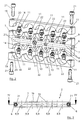
- Fig. 1 shows a corresponding structure of a Device indicated by dash-two-dotted lines Dosing valves 1, which are known per se and of which in the one shown in Fig. 1 Embodiment ten pieces to a central Dosing unit 2 are summarized.
- Dosing unit 2 for example with more or less Dosing valves 1, conceivable.
- the meaningful construction of a such dosing unit 2 would be for example a Dosing unit 2 with three metering valves 1, which then each at a distance of for example 90 ° would be arranged to each other. The remaining fourth Connection could then via a blind plug be closed.
- each of the metering valves 1 a Outlet opening 3, through which the metered Volume flow of the gaseous medium is discharged and of which he is above in their diameter comparatively small line elements (not shown) to the respective components of Fuel cell system can be performed.
- an electrical plug connection 4 through which it with the appropriate electronics for Control or regulation of the metering valve 1 or the Dosage amount, e.g. via an electromagnetic or electromechanical actuator, is connectable.
- the central functional element of the dosing unit 2 represents a central middle block 5.
- a Inlet opening 6 passes from the gaseous medium a compressor, not shown, or the like via a likewise not shown line element in the central middle block 5.
- a channel 7 is arranged, which the Inlet opening 6 with the respective connection points. 8 for the respective metering valves 1 connects.
- the middle block 5 has two central arranged openings 10, in which not shown Sensors for detecting the state variables of the gaseous medium before the metering valves 1, here especially pressure and temperature can.
- connection elements 11 of the metering valves 1 show Connection elements 11 of the metering valves 1.
- the exact Structure of these connection elements 11 is below already described, the corresponding reference numerals However, for reasons of clarity, they are only in Fig. 5 shown in more detail.
- a cylindrical training 12 which with a groove 13th for a seal 14, here an O-ring seal 14, is provided.
- the middle block 5 facing away from the side the connecting elements 11 has a thread 15, which in a corresponding inlet opening 16 each Metering valve 1 is screwed.
- This Screw in by means of a corresponding tool facilitate, has each of the connection elements eleventh also one in the manner of a hexagon trained area 17 on.
- FIG. 3 is a plan view according to the arrow III in FIG Fig. 1 can be seen on the dosing unit 2, wherein also here on a representation of the metering valves. 1 was waived.
- Fig. 1 and Fig. 2 already mentioned elements with the same ones Provided with reference numerals.
- Fig. 4 shows a cross section through this structure as shown in FIG. 3, in which case again the metering valves. 1 were also shown in a cross section to the interaction between metering valves 1 and To explain connection elements 11 in more detail.
- FIG. 4 shows, however, a second inlet 6 in the Channel 7, so that here, for example, from both sides the gaseous medium can be supplied, or it can be the cheaper side for the packaging be selected, the other one Inlet opening 6 then via a blind plug (not shown) must be closed.
- FIG. 4 are not yet explained mounting holes 22 through the central middle block 5 recognizable, which in no Functional relationship with the dosing unit 2 stand, but only to a fortification of the Middle block 5 on corresponding support elements of the Fuel cell system or vehicle serve.
- Fig. 5 shows in an enlarged view of Details V in Fig. 4 again the exact structure of Connection elements 11.
- the cylindrical formation 12 which is for example, from a standard connection element, which two threads and the hexagon 17 trained area, by turning off the make a thread easy to make.
- the seal 14 for example, an O-ring seal 14, picks up.
- the connecting element 11 during assembly the metering valves 1 pointed in the middle block 5.
Landscapes
- Engineering & Computer Science (AREA)
- General Engineering & Computer Science (AREA)
- Mechanical Engineering (AREA)
- Physics & Mathematics (AREA)
- Fluid Mechanics (AREA)
- Fuel Cell (AREA)
- Filling Or Discharging Of Gas Storage Vessels (AREA)
Description
- Fig. 1
- einen Aufbau der erfindungsgemäßen Vorrichtung mit Dosierventilen in einer dreidimensionalen Darstellung;
- Fig. 2
- eine Explosionsdarstellung eines zentralen Mittelblocks, mit Brückenelementen sowie Anschlußelementen;
- Fig. 3
- eine Draufsicht auf die erfindungsgemäße Vorrichtung gemäß dem Pfeil III in Fig. 1 ohne die Dosierventile;
- Fig. 4
- einen Querschnitt gemäß der Linie IV-IV in Fig. 3; und
- Fig. 5
- eine vergrößerte Darstellung des Details V in Fig. 4.
Claims (12)
- Brennstoffzellen-System in einem Kraftfahrzeug, mit einer Vorrichtung (2) zum Dosieren eines gasförmigen Mediums, insbesondere Luft, die mehrere Dosierventile (1) in mehreren Komponenten des Brennstoffzellen-Systems aufweist, wobei sämtliche Dosierventile (1) an einem zentralen Mittelblock (5) angeordnet sind und der Mittelblock (5) wenigstens eine Eintrittsöffnung (6) für das gasförmige Medium aufweist, welche über wenigstens einen Kanal (7) mit jeweils einer Anschlussstelle (8) für jedes der Dosierventile (1) verbunden ist.
- Brennstoffzellen-System nach Anspruch 1,
dadurch gekennzeichnet, dass
Anschlusselemente (11) an Einlassöffnungen (16) der Dosierventile (1) jeweils mit einer der Anschlussstellen (8) des Mittelblocks (5) dichtend im Eingriff stehen. - Brennstoffzellen-System nach Anspruch 1 oder 2,
dadurch gekennzeichnet, dass
in dem wenigstens einen Kanal (7) Sensoren angeordnet sind, durch welche Zustandsgrößen des gasförmigen Mediums erfaßbar sind. - Brennstoffzellen-System nach Anspruch 3
dadurch gekennzeichnet, daß
die Sensoren als wenigstens ein Drucksensor und wenigstens ein Temperatursensor ausgebildet sind, welche in zentralen Öffnungen (10) des Kanals (7) in dem Mittelblock (5) angeordnet sind. - Brennstoffzellen-System nach einem der Ansprüche 2 bis 4,
dadurch gekennzeichnet, daß
die Anschlußstellen (8) als Bohrungen (9) ausgebildet sind, wobei die Anschlußelemente (11) auf ihrer dem Mittelblock (5) zugewandten Seite eine zylindrische Ausbildung (12) aufweisen und mit der zylindrischen Ausbildung (12) in die Bohrungen einsteckbar sind. - Brennstoffzellen-System nach Anspruch 5,
dadurch gekennzeichnet, daß
die zylindrischen Ausbildungen (12) jedes Anschlußelements (11) wenigstens eine Dichtung (14) aufweisen. - Brennstoffzellen-System nach Anspruch 2 bis 6,
dadurch gekennzeichnet, daß
die Anschlußelemente (11) auf ihrer dem Mittelblock (5) abgewandten Seite mit den Einlaßöffnungen (16) der Dosierventile (1) verschraubt sind. - Brennstoffzellen-System nach einem der Ansprüche 1 bis 7,
dadurch gekennzeichnet, daß
der Mittelblock (5) in den die Anschlußstellen (8) umgebenden Bereichen Ausnehmungen (18) aufweist, in welchen die Dosierventile (1) wenigstens teilweise formschlüssig anliegen. - Brennstoffzellen-System nach einem der Ansprüche 1 bis 8,
dadurch gekennzeichnet, daß
die Dosierventile (1) über Befestigungseinrichtungen an dem Mittelblock (5) befestigt sind. - Brennstoffzellen-System nach Anspruch 9,
dadurch gekennzeichnet, daß
die Befestigungseinrichtung als jeweils mehrere Dosierventile (1) überspannendes Brückenelement (19) ausgebildet ist, wobei das Brückenelement (19) mit wenigstens einem Befestigungsmittel (21) an dem Mittelblock (5) befestigbar ist. - Brennstoffzellen-System nach Anspruch 10,
dadurch gekennzeichnet, daß
das Brückenelement (19) Ausnehmungen (20) aufweist, in welchen die Dosierventile (1) wenigstens teilweise formschlüssig anliegen. - Brennstoffzellen-System nach einem der Ansprüche 1 bis 11,
dadurch gekennzeichnet, daß
ein Durchmesser der Eintrittsöffnungen (6) deutlich größer ist als ein Durchmesser der jeweiligen Anschlußstellen (8).
Applications Claiming Priority (2)
| Application Number | Priority Date | Filing Date | Title |
|---|---|---|---|
| DE10035763 | 2000-07-22 | ||
| DE10035763A DE10035763B4 (de) | 2000-07-22 | 2000-07-22 | Vorrichtung zum Dosieren eines gasförmigen Mediums |
Publications (2)
| Publication Number | Publication Date |
|---|---|
| EP1174625A1 EP1174625A1 (de) | 2002-01-23 |
| EP1174625B1 true EP1174625B1 (de) | 2004-04-21 |
Family
ID=7649872
Family Applications (1)
| Application Number | Title | Priority Date | Filing Date |
|---|---|---|---|
| EP01117427A Expired - Lifetime EP1174625B1 (de) | 2000-07-22 | 2001-07-19 | Dosierventilanordnung zum Speisen eines gasförmigen Mediums in ein in einem Kraftfahrzeug eingesetztes Brennstoffzellen-System |
Country Status (3)
| Country | Link |
|---|---|
| US (1) | US6631736B2 (de) |
| EP (1) | EP1174625B1 (de) |
| DE (2) | DE10035763B4 (de) |
Families Citing this family (14)
| Publication number | Priority date | Publication date | Assignee | Title |
|---|---|---|---|---|
| US8235067B2 (en) * | 2009-05-15 | 2012-08-07 | Alphabio, Inc. | Encapsulated valve system |
| EP2600453A1 (de) * | 2011-12-01 | 2013-06-05 | Siemens Aktiengesellschaft | Brennstoffzellenblock |
| US9746391B2 (en) | 2013-10-30 | 2017-08-29 | Alphinity, Llc | Fluid monitoring device with disposable inner liner with sensor integration |
| KR102386708B1 (ko) | 2014-01-17 | 2022-04-14 | 알피니티, 엘엘씨 | 센서 기능을 가진 유체 모니터링 조립체 |
| US10087925B2 (en) * | 2014-12-05 | 2018-10-02 | Nextern, Inc. | Pneumatic distribution system using shared pump plenum |
| EP3869165B1 (de) | 2015-05-19 | 2023-12-13 | Repligen Corporation | Flüssigkeitsüberwachungsanordnung mit durchflusssensor und verfahren zur verwendung der flüssigkeitsüberwachungsanordnung |
| US9506606B1 (en) * | 2015-05-28 | 2016-11-29 | Fitok Incorporated | Fluid diversion device |
| EP3349843B1 (de) | 2015-09-15 | 2021-06-30 | Repligen Corporation | Schlauchmanagementsystem für pharmazeutische, bioprozessanwendungen und lebensmittel-/milchproduktanwendungen |
| KR102692528B1 (ko) | 2015-10-01 | 2024-08-06 | 리플리겐 코포레이션 | 방향성 유로를 갖는 밸브 조립체 |
| US10830259B1 (en) * | 2018-08-23 | 2020-11-10 | Keith Donald Brookins | Solenoid high pressure indexing valve system |
| KR102602359B1 (ko) * | 2018-11-22 | 2023-11-16 | 에이치엘만도 주식회사 | 체크밸브 및 이를 포함하는 모듈레이터블록 |
| CN111577940B (zh) * | 2019-02-19 | 2022-03-11 | 深圳市云和床垫有限公司 | 组接式供气组件 |
| DE102021114567A1 (de) | 2021-06-07 | 2022-12-08 | Gemü Gebr. Müller Apparatebau Gmbh & Co. Kommanditgesellschaft | Ventilblockkörper und Vorrichtung zur Anordnung des Ventilblockkörpers an einem Antriebskörper |
| CN221374574U (zh) * | 2024-01-15 | 2024-07-19 | 宁波汉奇机电有限公司 | 一种一出四的电磁阀管控制结构 |
Family Cites Families (12)
| Publication number | Priority date | Publication date | Assignee | Title |
|---|---|---|---|---|
| US3589387A (en) * | 1969-08-22 | 1971-06-29 | Int Basic Economy Corp | Integrated manifold circuits and method of assembly |
| GB1343679A (en) * | 1970-07-11 | 1974-01-16 | Danfoss As | Valve assemblies |
| US3698432A (en) * | 1970-10-08 | 1972-10-17 | Fluidic Controls Corp | Fluid logic module assembly with built-in manifold |
| DE2460295A1 (de) * | 1974-12-19 | 1976-07-01 | Lancier Masch Peter | Verteilertafel fuer druckluftueberwachungsanlagen |
| JPH02117072A (ja) * | 1988-10-26 | 1990-05-01 | Toyo Eng Corp | 燃料電池発電システム |
| US5232007A (en) * | 1992-07-16 | 1993-08-03 | Robertshaw Controls Company | Combination of a fuel manifold and a plurality of like fuel control devices mounted thereto, a manifold for such combination and methods of making the same |
| FI91015C (fi) * | 1993-01-14 | 1994-04-25 | Lauri Jauhola | Jakotukki |
| WO2000025049A1 (en) * | 1998-10-23 | 2000-05-04 | Chemand Corporation | Fluid handling port array |
| DE19947254A1 (de) * | 1999-09-30 | 2001-04-05 | Bosch Gmbh Robert | Vorrichtung zur Zufuhr flüssiger Medien zu Verbrauchern einer Brennstoffzellenanlage |
| DE10002004A1 (de) * | 2000-01-19 | 2001-08-09 | Bosch Gmbh Robert | Zerstäubungsvorrichtung |
| DE10002005A1 (de) * | 2000-01-19 | 2001-08-09 | Bosch Gmbh Robert | Zerstäubungsdüse |
| DE10020089B4 (de) * | 2000-04-22 | 2005-06-23 | Daimlerchrysler Ag | Verfahren und Vorrichtung zum dosierten Einbringen eines Flüssigkeitsvolumenstroms in ein System |
-
2000
- 2000-07-22 DE DE10035763A patent/DE10035763B4/de not_active Expired - Fee Related
-
2001
- 2001-07-19 DE DE50102031T patent/DE50102031D1/de not_active Expired - Lifetime
- 2001-07-19 EP EP01117427A patent/EP1174625B1/de not_active Expired - Lifetime
- 2001-07-23 US US09/910,003 patent/US6631736B2/en not_active Expired - Fee Related
Also Published As
| Publication number | Publication date |
|---|---|
| US20020043288A1 (en) | 2002-04-18 |
| DE10035763B4 (de) | 2006-07-27 |
| DE50102031D1 (de) | 2004-05-27 |
| DE10035763A1 (de) | 2002-05-16 |
| US6631736B2 (en) | 2003-10-14 |
| EP1174625A1 (de) | 2002-01-23 |
Similar Documents
| Publication | Publication Date | Title |
|---|---|---|
| DE10035763B4 (de) | Vorrichtung zum Dosieren eines gasförmigen Mediums | |
| DE3629226C2 (de) | Proportionales elektrohydraulisches Drucksteuerventil | |
| EP1084369B1 (de) | Regeleinrichtung für gasbrenner | |
| EP0909898B1 (de) | Druckluftwartungseinheit | |
| EP1573210B1 (de) | Fluidtechnisches steuergerät | |
| EP0938360B1 (de) | Adsorptionstrockneranlage und verfahren zu ihrer funktionsüberprüfung | |
| DE19521832A1 (de) | Druckmeßvorrichtung | |
| DE2122585A1 (de) | Verfahren und Vorrichtung zum Messen einer Gasströmung | |
| DE10245815A1 (de) | Druckluftsteuervorrichtung und Luftfederungsanlage für ein Fahrzeug | |
| DE102017124194A1 (de) | Überwachungsgerät für eine spritzgussform | |
| WO1998041766A1 (de) | Plattenartige montagebasis | |
| EP0864859A1 (de) | Modularer steuerblock für die Analysentechnik | |
| DE4404224A1 (de) | Hydraulische Funktionseinheit | |
| EP2180226B1 (de) | Modulares Fluidverteilsystem | |
| WO2021217195A1 (de) | Messsystem zur messung eines durchflusses | |
| DE102015212431A1 (de) | Brennstoffversorgungseinheit | |
| DE2754430A1 (de) | Steuereinrichtung fuer mindestens zwei verstellbare pumpen | |
| EP0386326A1 (de) | Volumenstrom-Kontrollsystem für Schmieranlagen | |
| EP3714822B1 (de) | Fluidsteueranordnung für ein medizinisches gerät | |
| DE20310275U1 (de) | Verteilereinheit für flüssige Temperiermedien, insbesondere von Temperiersystemen für Spritzgießwerkzeuge | |
| EP2984446B1 (de) | Vorrichtung zur pneumatischen objektvermessung | |
| AT521524B1 (de) | Gasmischvorrichtung zur Kalibrierung von Gasanalysatoren | |
| DE10244139A1 (de) | Sicherheitssystem für den Betrieb wasserstoffumsetzender Vorrichtungen in geschlossenen oder teilgeschlossenen Räumen oder Behältern | |
| EP2191341B1 (de) | Stofftransport und ereigniskontrolle in systemen mit piezoelektrisch aktivierter tröpfchenemission und kombinationsmöglichkeiten von trägermatrix und zu dosierendem stoff | |
| WO2025215163A1 (de) | Massenstromregelventil zur inertgasversorgung eines waferbehälters |
Legal Events
| Date | Code | Title | Description |
|---|---|---|---|
| PUAI | Public reference made under article 153(3) epc to a published international application that has entered the european phase |
Free format text: ORIGINAL CODE: 0009012 |
|
| AK | Designated contracting states |
Kind code of ref document: A1 Designated state(s): AT BE CH CY DE DK ES FI FR GB GR IE IT LI LU MC NL PT SE TR Kind code of ref document: A1 Designated state(s): DE FR GB IT |
|
| AX | Request for extension of the european patent |
Free format text: AL;LT;LV;MK;RO;SI |
|
| 17P | Request for examination filed |
Effective date: 20011130 |
|
| RAP1 | Party data changed (applicant data changed or rights of an application transferred) |
Owner name: BALLARD POWER SYSTEMS AG |
|
| AKX | Designation fees paid |
Free format text: DE FR GB IT |
|
| 17Q | First examination report despatched |
Effective date: 20021209 |
|
| GRAP | Despatch of communication of intention to grant a patent |
Free format text: ORIGINAL CODE: EPIDOSNIGR1 |
|
| GRAS | Grant fee paid |
Free format text: ORIGINAL CODE: EPIDOSNIGR3 |
|
| GRAA | (expected) grant |
Free format text: ORIGINAL CODE: 0009210 |
|
| AK | Designated contracting states |
Kind code of ref document: B1 Designated state(s): DE FR GB IT |
|
| PG25 | Lapsed in a contracting state [announced via postgrant information from national office to epo] |
Ref country code: FR Free format text: LAPSE BECAUSE OF FAILURE TO SUBMIT A TRANSLATION OF THE DESCRIPTION OR TO PAY THE FEE WITHIN THE PRESCRIBED TIME-LIMIT Effective date: 20040421 Ref country code: IT Free format text: LAPSE BECAUSE OF FAILURE TO SUBMIT A TRANSLATION OF THE DESCRIPTION OR TO PAY THE FEE WITHIN THE PRESCRIBED TIME-LIMIT;WARNING: LAPSES OF ITALIAN PATENTS WITH EFFECTIVE DATE BEFORE 2007 MAY HAVE OCCURRED AT ANY TIME BEFORE 2007. THE CORRECT EFFECTIVE DATE MAY BE DIFFERENT FROM THE ONE RECORDED. Effective date: 20040421 Ref country code: GB Free format text: LAPSE BECAUSE OF FAILURE TO SUBMIT A TRANSLATION OF THE DESCRIPTION OR TO PAY THE FEE WITHIN THE PRESCRIBED TIME-LIMIT Effective date: 20040421 |
|
| REG | Reference to a national code |
Ref country code: GB Ref legal event code: FG4D Free format text: NOT ENGLISH |
|
| REG | Reference to a national code |
Ref country code: IE Ref legal event code: FG4D Free format text: GERMAN |
|
| REF | Corresponds to: |
Ref document number: 50102031 Country of ref document: DE Date of ref document: 20040527 Kind code of ref document: P |
|
| GBV | Gb: ep patent (uk) treated as always having been void in accordance with gb section 77(7)/1977 [no translation filed] |
Effective date: 20040421 |
|
| REG | Reference to a national code |
Ref country code: IE Ref legal event code: FD4D |
|
| PLBE | No opposition filed within time limit |
Free format text: ORIGINAL CODE: 0009261 |
|
| STAA | Information on the status of an ep patent application or granted ep patent |
Free format text: STATUS: NO OPPOSITION FILED WITHIN TIME LIMIT |
|
| EN | Fr: translation not filed | ||
| 26N | No opposition filed |
Effective date: 20050124 |
|
| PGFP | Annual fee paid to national office [announced via postgrant information from national office to epo] |
Ref country code: DE Payment date: 20140930 Year of fee payment: 14 |
|
| REG | Reference to a national code |
Ref country code: DE Ref legal event code: R119 Ref document number: 50102031 Country of ref document: DE |
|
| PG25 | Lapsed in a contracting state [announced via postgrant information from national office to epo] |
Ref country code: DE Free format text: LAPSE BECAUSE OF NON-PAYMENT OF DUE FEES Effective date: 20160202 |