EP1174273B1 - Ink jet recording method, recording apparatus and data processing method - Google Patents
Ink jet recording method, recording apparatus and data processing method Download PDFInfo
- Publication number
- EP1174273B1 EP1174273B1 EP01117595A EP01117595A EP1174273B1 EP 1174273 B1 EP1174273 B1 EP 1174273B1 EP 01117595 A EP01117595 A EP 01117595A EP 01117595 A EP01117595 A EP 01117595A EP 1174273 B1 EP1174273 B1 EP 1174273B1
- Authority
- EP
- European Patent Office
- Prior art keywords
- thinning
- recording
- boundary
- data
- inks
- Prior art date
- Legal status (The legal status is an assumption and is not a legal conclusion. Google has not performed a legal analysis and makes no representation as to the accuracy of the status listed.)
- Expired - Lifetime
Links
Images


Classifications
-
- B—PERFORMING OPERATIONS; TRANSPORTING
- B41—PRINTING; LINING MACHINES; TYPEWRITERS; STAMPS
- B41J—TYPEWRITERS; SELECTIVE PRINTING MECHANISMS, i.e. MECHANISMS PRINTING OTHERWISE THAN FROM A FORME; CORRECTION OF TYPOGRAPHICAL ERRORS
- B41J2/00—Typewriters or selective printing mechanisms characterised by the printing or marking process for which they are designed
- B41J2/005—Typewriters or selective printing mechanisms characterised by the printing or marking process for which they are designed characterised by bringing liquid or particles selectively into contact with a printing material
- B41J2/01—Ink jet
- B41J2/07—Ink jet characterised by jet control
-
- B—PERFORMING OPERATIONS; TRANSPORTING
- B41—PRINTING; LINING MACHINES; TYPEWRITERS; STAMPS
- B41J—TYPEWRITERS; SELECTIVE PRINTING MECHANISMS, i.e. MECHANISMS PRINTING OTHERWISE THAN FROM A FORME; CORRECTION OF TYPOGRAPHICAL ERRORS
- B41J2/00—Typewriters or selective printing mechanisms characterised by the printing or marking process for which they are designed
- B41J2/005—Typewriters or selective printing mechanisms characterised by the printing or marking process for which they are designed characterised by bringing liquid or particles selectively into contact with a printing material
- B41J2/01—Ink jet
- B41J2/21—Ink jet for multi-colour printing
- B41J2/2132—Print quality control characterised by dot disposition, e.g. for reducing white stripes or banding
-
- G—PHYSICS
- G06—COMPUTING; CALCULATING OR COUNTING
- G06K—GRAPHICAL DATA READING; PRESENTATION OF DATA; RECORD CARRIERS; HANDLING RECORD CARRIERS
- G06K15/00—Arrangements for producing a permanent visual presentation of the output data, e.g. computer output printers
- G06K15/02—Arrangements for producing a permanent visual presentation of the output data, e.g. computer output printers using printers
- G06K15/10—Arrangements for producing a permanent visual presentation of the output data, e.g. computer output printers using printers by matrix printers
- G06K15/102—Arrangements for producing a permanent visual presentation of the output data, e.g. computer output printers using printers by matrix printers using ink jet print heads
- G06K15/105—Multipass or interlaced printing
- G06K15/107—Mask selection
Definitions
- the present invention relates to an ink jet recording method, a recording device and a data processing method in which high quality images can be formed on a recording material with suppressed banding nonuniformly, more particularly to the ink jet recording method, the recording device and the data processing method in which the recording is carried out through one-path or multi-path printing.
- the present invention is applicable to any equipment using as the recording material, paper, textile, leather, nonwoven fabric, OHP sheet, metal or the like. More particularly, the present invention is applicable to a printer, copying machine, facsimile machine or another office equipment, industrial manufacturing machines or the like.
- the demand for high-speed printing picks up.
- the number of paths is the number of scans of the carriage required to complete one line of printing.
- the sheet feeding distance per unit can be increased by reducing the number of paths.
- the speed can simply be doubled by changing it to one-path printing. That is, the reduction of the number of paths reduces the number of scans to cover a predetermined area (one sheet, for example), and increases the distance of sheet feed, so that time required for printing is shortened.
- the duty (ratio) of the recording ink ejected per unit time is larger than when the one band area is printed through a plurality of scans (multi-path printing). Therefore, the production of the black stripe between the adjacent bands (paths) is remarkable at the portions where the printing duty is high, although it is different depending on the nature of the recording material and the recording liquid.
- the black stripe appearing at the adjacent bands is called connecting stripe, spending or the like. It might deteriorate the image to such an extent that image is practically unsatisfactory.
- Japanese Laid-open Patent Application 11-188898 discloses a serial scanning type in which a recording head repeatedly scans the recording material in the main scan direction to print the image band by band, a method is used to avoid the production of a stripe at the connecting portion between the adjacent bands. More particularly, at least one of the first and the last raster lines of one band covered by one scan of the recording head is divided into a plurality of unit areas including a predetermined number of dots. In accordance with the image data, more particularly, with a sum of an amount of ink ejection for a noting color in each of the divided areas and an amount of ink ejections for the other in the unit areas, the amount of the ink actually ejected is reduced (thinning).
- the ink jet recording apparatus according to claim 1.
- the data processing method according to claim 20 for effecting recording on a recording material by ejecting a plurality of inks with relative scanning movement between a recording head and the recording material.
- a discrimination is made on the basis of the number of recording data (the number of dots to be printed) adjacent the boundary area as to the color area (hue and chromaticity) of a unit area (noting region), and the thinning rank is determined for each of the used inks and for each of the printing positions in accordance with the discriminated color area.
- a neighborhood of a connecting or boundary portion of the data of one band is divided into a plurality of unit areas, and the number of dots for each of the unit areas are counted, and then, the color area of a noted area is discriminated on the basis of the dot counts for the respective colors.
- a thinning rank for each thinning process area is determined for each color on the basis of a predetermined thinning rank graph and a dot count (or printing duty) for each unit area provided by a sum of the dot counts for each color in the color area.
- the area in which the thinning process is executed is several raster areas (4 rasters, for example) at a sheet inlet side (upstream side with respect to the feeding direction of the sheet) in one scan area to be printed. It is noted that thinning beforehand, that is, the thinning in the sheet feeding side is preferable than the other, since the margin relative to the recording material is large. By doing so, a larger number of recording materials can be supported than in the case that thinning processes effected at the sheet discharging side on the basis of one parameter.
- the degrees (rank graph, in this example) of thinning can be independently selected for each raster areas or for each several raster areas, by which, for example, the degree of thinning can be made higher in the area closer to the boundary than in the other areas, thus improving the accuracy of the thinning process.
- the area in which the dots are counted is 16 dot x 16 raster areas (dot) astride the boundary area. Since the area in which the dots are counted is larger than the thinning area so that print data of the bands astride the boundary are counted, the circumstances influential to the bleeding at the boundary can be taken into consideration.
- the thinning process for the print data in this embodiment is a so-called SMS (sequential multi-scan) type.
- Other thinning processing methods include a type using a pattern mask and an error diffusion (ED) type.
- a mask of staggered arrangement is used for example (pixel data of white parts are skipped), and when the print data having the same amounts of ink ejections as shown in Figure 22B. C, are processed, the data after the process are shown in Figures 22D and 22E, and the print data at the "x" portions are skipped.
- the thinning mask and the print data interfere in the case of the data of the same ejection amount (duty), depending on the arrangement of the print data, and therefore, the amount of thinning cannot be controlled in some cases.
- a multi-level value is assigned in accordance with a predetermined nozzle correction value:
- the use is made with a so-called SMS thinning process to accomplish both of the uniformation of the amount of thinning and the high speed processing.
- SMS thinning process whenever there is a printing datum, the count designated by the counter (register) (particular bit; MSB, for example), and if it is "1", the print data is not skipped (printed), and on the other hand, if the counter value is "0", the print data is skipped (thinned) (not printed).
- the counter is shifted to the right (bit shift). When the counter is shifted to the right side end, it returns to the left end (cyclic shifting).
- FIGS 23A, B schematically show an example of penetration of the recording ink into the recording material.
- the behavior of penetration of the recording ink is different depending on the material of the recording ink, the recording material, the ambient conditions, differences in the time interval between prints or the like, though.
- the later printed recording ink 232 sink under the first printed recording ink 231.
- the recording inks printed onto the same position on the recording material do not mix with each other, usually, and the coloring occurs with the situation shown in Figure 23A.
- the later printed ink has a coloring which is different from that inside 234 in the inside.
- the later printed ink has a stronger coloring than the first printed ink. This functions also to worsen the connecting seam at the boundary. Therefore, even if the same thinning rate is used for the recording ink to be first printed and the recording ink to be later printed, the differences in the coloring at the marginal area are not avoided. Therefore, in this embodiment, the thinning rate is determined in consideration of the order of depositions of the ink onto the recording material.
- Figure 10A shows an example of a rank graph for a thinning to be used for determining the thinning rate in this embodiment.
- the thinning rank graph gives ranks corresponding to the dot counts in the dot count area for each of the inks which is subjected to the thinning process.
- the thinning rank graph is designated on the basis of three values, namely, a start dot number, the dot interval and the MAX rank.
- the levels of the thinning ranks are determined beforehand. In this embodiment, for example, there are nine levels, namely, 0%, 12.5%, 25%, 37.5%, 50%, 62.5%, 75%, 87.5% and 100%.
- the start dot number is the total dot count at which the use of the thinning rate12.5% (thinning rank 1) is started.
- the dot interval is the dot count before the next thinning rate (25% if the current thinning rate is 12.5%), that is, the range of the dot count using the same thinning rate.
- MAX rank is the maximum thinning rate, that is, no thinning rate beyond that is not selectable. If the thinning rate reaches the MAX rank, the thinning rate is not raised, and the MAX rank thinning rate is maintained even if the dot count reaches the number corresponding to the dot interval.
- one thinning line in the rank graph can be expressed by 1 bite ((8 bits); one component (8 levels) for the start dot number, one component for the duct interval (8 levels), and one component (4 levels) for the MAX rank 1.
- the number of bits may be increased.
- the number of bits is not changed, but a common offset value may be given commonly to the start dot number, the dot interval and the MAX rank, by which the parameters can be more accurately set.
- the amount of the data required for setting the thinning rank graph is particularly preferable in this embodiment.
- the reason is as follows.
- use of hardware prefers to the use of software. This is because the speed of the data processing using the software is not enough to catch up with the printing speed. It is preferable to use hardware such as a gate array. In this case, the number of required data is directly influential to the number of gates, and therefore, less number of data is preferable from the standpoint of the circuit scale.
- Figure 10B shows another example of the thinning rank. This example is particularly effective in such a case that inclination of the thinning rank line is desirably changed.
- the behavior on the recording material after the actual printing is different, and the conspicuousness of the boundary line and the effectiveness to the boundary line after the thinning process is also different.
- the printing is carried out using the cyan ink and the magenta ink where the color is changing toward blue, and at the position where the blue reaches the maximum level, the solid printing occurs for the cyan and magenta colors (the data of maximum duty).
- a certain high degree of thinning process is effected to the cyan and magenta colors.
- the cyan ink is first started to be used at the point of change from the red at the maximum to the UC.
- the data for the magenta have the maximum duty level which is the same as the position where the gradation changes from the blue to the black in the foregoing white - blue - black gradation example, and therefore, the highly thinning rate used for the cyan and magenta colors in the foregoing example, is used in this example.
- the connecting process in the boundary area in the formation of color images that in addition to the conventionally used total amount of the ink to be applied to the unit area adjacent to the end portion, the information relating to the hue and the chromaticity of the unit area and the information as to which recording ink is used for printing is obtained, and that thinning rate is selectable on the basis of these pieces of information.
- the discrimination is made as to the hue and the chromaticity of the noting area (unit area) from the dot count for each color.
- the term color area is used as a word covering both of the hue and the chromaticity in combination.
- the color area of the noting area is discriminated from the number of recording data (the number of dots to be printed) in the neighborhood of the boundary area between adjacent bands, and in accordance with the color area, the thinning rank (the degree of thinning) can be selected for each of the used ink and the recording positions. Using the selected thinning rank, the thinning process is effected to each of the inks, so that conspicuousness of the boundary line between adjacent bands can be suppressed in the one-path printing.
- the first embodiment creates to a recording system in which the plurality of recording heads are used to effect recording on the recording material with recording ink.
- Figure 1 is a schematic perspective view of a major part of an ink jet recording apparatus according to the first embodiment of the present invention.
- a plurality of (3, in this embodiment) head cartridges 1A, 1B, 1C are replaceably mounted on the carriage 2.
- Each of the cartridges 1A-1C is provided with connector for receiving a signal for driving the recording head.
- the term "recording means" (recording head or head cartridge) is used.
- the respective cartridges 1 function to print different color inks. Therefore, the ink containers contain cyan, magenta, yellow inks and so on which have different colors.
- Each of the recording means 1 is exchangeably positioned and carried on the carriage 2 the carriage 2 is provided with a connector holder (electrical connecting portion) for transmission the driving signal or the like to each of the recording means 1 through the connector.
- the carriage 2 is supported and guided on a guiding shaft 3 extending in the main scan direction in the main assembly of the apparatus, and is movable in the main scanning direction.
- the carriage 2 is driven and controlled by the main-scanning motor 4 through a motor pulley 5, a driven pulley 6 and a timing belt 7.
- the recording material 8 such as a sheet of paper, thin plastic resin sheet or the like is fed through a recording position where the recording material is faced to the ejection outlet side surface of the recording head 1 by the rotation of the two pairs of feeding rollers.
- the recording material 8 is supported on a platen (unshown) at the back side so as to provide a flat recording surface in the recording position.
- each of the cartridges 1 carried on the carriage 2 has the ejection outlet side surface which is projected downwardly from the carriage 2, and is supported to be parallel with the recording material 8 between the pairs of feeding rollers.
- the recording head 1 is in the form of an ink jet recording means which ejects the ink using the thermal energy, and is provided with electrothermal transducers for generating thermal energy.
- film boiling is caused by the thermal energy applied by the electrothermal transducer.
- a pressured change is produced so as to eject the ink.
- Figure 6 illustrates a structure of nozzles of the recording heads.
- FIG. 2 is a schematic perspective view illustrating a major part of an ink ejection portion 13 of the recording head 1.
- the ejection side surface 21 is faced to the recording material 8 with a gap of approx. 0.5-2 mm, and is provided with a plurality of (256 in this embodiment) ejection outlets 22 at a predetermined intervals (360dpi in this embodiment).
- the recording head further includes a common liquid chamber 23 and flow paths 24 for fluid communication between the common liquid chamber 23 and the ejection outlets 22.
- Each of the flow paths 24 is provided of the wall constituting the path with an electrothermal transducer 25 (heat generating resistor, for example) which is effected to generate energy corresponding to the amount of the ink ejection.
- the recording heads 1 are carried on the carriage 2 in the manner that said ejection outlets 22 are arranged in the direction crossing with the scanning direction of the carriage 2.
- the electrothermal transducers 25 corresponding to the image signals or to the ejection signals are actuated (energized) to cause a film boiling in the ink in the flow path 24, and the pressure produced by the boiling functions to eject the ink through the ejection outlet 22.
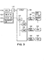
- Figure 3 schematically illustrates a control circuit used in the ink jet printing apparatus shown in Figure 1.
- a controller 100 constitutes a main controller and includes a CPU101 in the form of a microcomputer, a ROM 103 storing a program, a table, fixed data or the like, and a RAM 105 providing an area for conversion of the image data and a working area.
- the host apparatus 110 is the supply source of the image data, and it may be a computer which produces and processes image data or the like relating to the printing, or it may be a reader portion for reading images.
- the image data, the command, the status signal and the like are supplied to or receive from the controller 100 through an interface (I/F).
- An operating portion 120 include a group of switches operable by the operator, a main switch 122, a print start switch 124, a recovery switch 126 for actuating suction recovery operation.
- a head driver 140 actuates the ejection heaters 25 of the print head 1 in accordance with the print data or the like.
- the head driver 140 includes a shift register for aligning the print data corresponding to the positions of the ejection heater 25, a latching circuit for effecting latching at proper timing, a logic circuit element for actuating the ejection heater in synchronism with the drive timing signal, a timing setting portion for properly setting the actuation timing for correct positioning of the dot formation.
- the print head 1 is provided with a sub-heater 142.
- the sub-heater 142 functions to control the temperature in order to stabilize the ejection property of the ink, it may be formed on the print head substrate simultaneously with the ejection heater 25, or it may be mounted to the main assembly of the print head or the head cartridge.
- the motor is to drive the main-scanning motor 152, and the sub-scan motor 162 is for feeding the print medium 8 (sub-scan), the motor driver 150 is a driver for the motor.
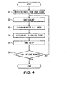
- Figure 4 is a flow chart showing operations from the reception of the amount of the print data corresponding to one scan to the end of the print data process.
- step S1 the amount of the print data required for printing one scan for each of the different color inks.
- the data for one band is necessary, and the data in the dot count area of the next band are required as well.
- one band is a printing area printed by one carriage scanning operation.
- a step S2 executes the dot count operation
- a step S3 executes the color area discrimination
- a step S4 executes the thinning rank determining operation
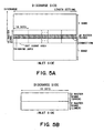
- a step S5 effects the SMS thinning process, for each of the unit areas, that is, each of 16 dots x 16 dots raster areas shown in Figure 5.
- step S6 the foregoing process is repeated until one band is covered. The description will be made as to the respective processes.
- the area subjected to the dot count operation is a width corresponding to the 16 raster lines including the connecting portions between adjacent bands.
- the dot count operation is carried out for all of the recording inks carried on the recording device of this embodiment, more particularly, the dot count operation is carried out for the binary data for the cyan, magenta and yellow colors. A sum of the dot counts of them is the dot count (or the total dot count) as a result of the dot count operation.
- the event that dot count is "1" means that one dot is present in one pixel
- the event that dot count is "2" means that two dots are present in one pixel.
- the thinning rank is determined from the total dot count obtained by the dot count step, and the SMS thinning process is carried out. It is possible to obtain relative information indicative of the relative relation among the amounts of the inks printed in the unit areas, from the dot counts for each of the colors, and the discrimination is made as to the color area (hue and chromaticity) of the unit area from the relative information.
- Such a process is repeated for one band until all of the bands corresponding to one page are subjected to the process, so that print data are generated.
- the total dot count is the simple total sum of the dot counts of the cyan, magenta and yellow colors, but the counts may be weighted depending on the colors when the degrees of influence to the production of the boundary strike are not uniform. For example, in a case, the conspicuousness of the boundary line is worsened by the yellow ink, then, the dot count for the yellow color may be weighted, for example, the dot count of the yellow is multiplied by 1.2. In another case, the ejection amounts are different depending on colors (for example, in the amount of the ejected red ink is larger than the other, then, this is taken into account.
- the data processing may be carried out only for the small areas which is adjacent to the boundary between bands (that is, the end portion of the array of the nozzles. Therefore, the load required by the process is small, such that even in the case that time period which can be given to the process is short as in the case of one path printing.
- the dot count operation is sequentially carried out for each of the dot count unit areas for all of the range determined by the set length, and the corporations are carried out for all of the dot count unit areas, by which the dot count operation for 1 band is completed.
- the state of print dots before and after the boundary can be known. More particularly, it is possible to discriminate whether or not the ink ejections tend to produce the boundary line, and therefore, a high precision boundary processing is accomplished.
- the dot count operation is carried out only for the areas within one band, it is possible to predict the degree of ink bleeding attributable for the production of stripes within the band, but it is not possible to predict the degree of influence to the next band.
- the production of the boundary line or stripe is dependent on the amount of the ink adjacent the boundary between the adjacent bands.
- the boundaries stripe is suppressed due to the ink bleeding.
- the amount of the ink is small, the possibility of the production of the stripe is not high, although the ink bleeding may occur.
- the next band ink is shot. Then, in the process of the next ink penetrating into the material of the sheet or on the surface thereof, the next ink is considered as being attracted to the ink of the previous shot. At this time, if no processing is given to the boundary area, the amount of the ink at the boundary becomes larger, is shown in Figure 13A with the result of a darker boundary. This is considered as the cause of the production of the stripe.
- the boundary processing is carried out as shown in Figure 13B to reduce the amount of the ink either in the first or second band, that is, the print data are thinned.
- the thinning process may be carried out in one of the first and second bands or in both of them.
- boundary stripe is attributable to the amounts of the ink in the adjacent bands. Therefore, the selection of the areas to be processed extend astride the boundary is effective for the processing.
- the data for the first band or the second band may be weighted. For example, when the cause of the stripe production is the amount of the ink, the dot count of the first shot band may be multiplied by 1.2, so that amount of the ink in the first band may be sensitively taken into account.
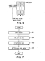
- Figure 7 is a flow chart for the color area selection.
- step S2 the dot count operations are carried out for the respective colors.
- Figure 8 shows an example of dot count in a unit area
- Figure 9 shows sections of color areas used in this embodiment.
- the order of the number of dots is the magenta, the cyan and the yellow (smallest).
- the portion of yellow with which the dot count is the minimum among the three colors is called "UC" (under color)
- the portion resulting from the cyan (second largest) deducted by the UC is the secondary color (D2, blue in this embodiment) portion.
- the portion of the magenta (the largest) detected by the second largest cyan is the primary color (D1, magenta in this embodiment).
- the D1, D2, UC are calculated in a step S31.
- the largest among the D1, D2, UC is discriminated, by which the position of the noting dot count area (unit area) in Figure 9 is determined (step S32).
- D1 is the largest, and therefore, it is discriminated that dot count area is in the cyan.
- the color area is selected in the order of UC, D2, D1 (if UC and D2 are the same, UC, is selected; if D1 and D2 are the same, D2 is selected, and therefore, D1 is not used actually).
- Figure 10A shows an example of a rank graph for determining the thinning rank.
- Figure 10A is plots of the total dot count (ordinates) vs. the thinning rank corresponding to the thinning rate (abscissas). Using the graph, the thinning rate for the data (count in the SMS processing) is designated on the basis of the total dot count for the unit area, obtained by the dot count process.
- the thinning rates are one of 0%, 12.5%, 25%, 37.5%, 50%, 62.5%, 75%, 87.5%, 100% (nine levels).
- the counter value is shown in Figure 11.
- the designation of the thinning rank graph is determined on the basis of the number of the start dot, the dot clearance and the MAX rank.
- Figure 10A also shows the correspondence of the three parameters and the thinning rank graph.
- the three parameters are the start dot number, the thinning clearance and the MAX rank, in accordance with which the thinning rank graph is selected.
- this way of selection is not limiting in the present invention.
- another method is such that thinning rank graph per se is speculated.
- the number of levels of the thinning rates is not necessarily limited to nine, but may be increased as desired.
- Figure 12 shows an example of the thinning rank graph used in this embodiment. As described in the foregoing, the thinning rank graph is determined properly for each color, and Figures 12A-F show an example for one color area (cyan).
- the thinning rank is designated for each of different inks (cyan, magenta and yellow).
- the thinning area is divided into two portions in the sheet discharge direction (sub-scan direction), and the thinning rank graphs are selected independently from each other. Therefore, in Figures 12A-F, six thinning rank graphs are used (cyan upper, cyan lower, magenta upper, magenta lower, yellow upper and yellow lower).
- Figures 12A-F show only the graphs for the color areas (cyan in this example) discriminated as a result of color area discriminating operation. Actually however, such a combination is present in each of the magenta, the yellow and the UC.
- control can be responsive to the difference in the degree of the boundary stripe due to the difference in the behavior on the recording material depending on the inks, the difference in the conspicuousness due to the difference in the lightness and/or the chromaticity depending on the inks.
- the thinning rank graph can be set for each color, and the process can be responsive to the change in the color at the end portion resulting from the order of shots onto the recording material.
- the change in the color at the end portion is like this.
- the behavior of the ink is dependent on the time difference of the ink ejections onto the recording material and on the property of the recording material, but in the case that time difference of the objections is very short because of the lateral arrangement of the recording heads, an outline bordering of magenta color is produced when the cyan and magenta inks are shot at the same position on plain paper, for example. In such a case, that is, the outline color change occurs, the changing of the thinning pressure is effective. More specifically, in the case of the shots in the order of cyan ink and magenta ink, the thinning ratio for the magenta is made higher than that for the cyan, by which the boundary stripe can be suppressed more.
- the data of 4 raster areas at the sheet feeding side in one band are processed, and therefore, the data in the area of 16 dots in the main scan direction are processed. Furthermore, as shown in Figure 5A, the 4 raster area is divided into 2 raster areas at the sheet discharge side (upper) and 2 raster areas at the sheet feeding side (lower). For each of the defined in the areas, the thinning rank can be selected, that is, different thinning rank graphs are prepared.
- the thinning area and the dot count area used in this embodiment are not the same area, but only a part of the dot count area is the thinning area. It is not necessary that thinning area and the dot count area are the same.
- the causes of the production of the boundary stripe is not so simple that problem may be solved by the boundary per se, but it is considered that ink bleeding between the bands and the ink bleeding away from the portion by several raster lines propagates through chain reaction depending on the connections of the dots.
- the boundary stripes are different between when the ink is ejected only for 4 raster lines at up to the boundary and when the ink is ejected for 8 raster lines. More particularly, the stripe is more remarkable in the latter. Because the ink bleeding occurring at the position several rasters away from the boundary gradually propagates with the result of the amount of the ink at the boundary is relatively large, and therefore, the boundary stripe is relatively remarkable. Therefore, it is desirable that dot count area is larger than the thinning area and is determined in consideration of the chain reaction propagation of the ink bleeding. In this embodiment, the dot count area twice as large as the thinning area.
- the size of the thinning area it is desirable that it has a certain area from the standpoint of effectiveness of the processing. If, however, it is too large, the density may become too low due to the thinning process with the possible result of white stripe. In view of these factors and properties of thing, proper width of the thinning area is determined.
- the thinning area has a width corresponding to the 4 raster areas (0.17mm in the case of 600dpi). This is effective to suppress the boundary stripe without inducing the white stripe.
- 4 raster lines are used for the thinning process area, and the area is divided into two parts. This is not limiting, and it may be divided into four parts, that is, the rank graphs are assigned to the respective raster lines.
- the causes of the production of the boundary stripe are not so simple that chain reaction from the ink bleeding occurring at the position several raster lines away from the boundary is desirably taken into account. Therefore, it is more effective to process the neighborhood of the boundary in view of the ink bleeding than to process the boundary portion only.
- the one raster or two rasters at the boundary is a course of the production of the boundary stripe.
- the degree of the influence changes away from the boundary (by one raster line, two raster line, three raster line -----). Adjacent to the boundary, the raster lines in an area is concerned with the production of the boundary stripe, and the decrees of the influences are different.
- the thinning ranks are determined for the respective raster lines.
- the thinning ranks are determined in accordance with the distance from the boundary, by which the accuracy of the processing is improved.
- the designated count (specified bit, for example, MSB in this embodiment) is read by the counter (register) each time the print data is supplied, if it is "1", the print datum is printed, and then the counter is shifted rightward by "1". If the counter "0”, the print data is thinned, and then the counter is shifted rightward by "1". When the counter reaches the rightmost position, it is returned to the leftmost position. The process is repeated each time the print data it supplied, thus determining the dots to be skipped.
- the first print datum is "o", and the count is 0, and therefore, the first data is skipped or removed. Therefore, the first print datum after the processing is "x", and the counter shifts by one to the right ( Figure 14B).
- the next datum is not indicative of printing, and is maintained “x”, and the counter does not shift and is retained there ( Figure 14C).
- the third print data has the counter value of "1”, and the print datum remains, and the counter is shifted by one to the right. In this manner, the print data are skipped at the ratio of 1 out of 4 ( Figure 14D).
- Figure 15A-F shows an example of the data before and after the thinning process in which the thinning process is effected in the area defined by 8 dots in the main scan direction and 4 raster lines in the sheet discharge direction (one half in the main scan direction) since the thinning process area is constituted by 4 raster lines, in this example, the thinning ranks are "2" at the sheet discharge and "4" at the sheet feeding side, respectively.
- the raster lines are called “first raster”, “second raster”, “third raster”, “fourth raster” from the sheet discharge side in Figure 15A.
- the SMS thinning process is carried out from the sheet discharge side raster for each of the rasters. After the processing for one raster, the next raster is processed.
- the SMS counter does not return to the initial position even if the thinning level is changed.
- the SMS counter does not return to the initial position even if the thinning process area is shifted to the adjacent area within the same band, and the counter position is retained in one band. When the operations shifted into a different band, the counter position is returned to the initial position.
- the initial position in the first process area in one band is randomly designated.
- the processing from the first raster to the fourth raster is as shown in Figure 15B, and it is as shown in Figure 15F as a whole.
- the color area of the noting area is discriminated from the number (the number of dots to be printed) of the recording data neighborhood the boundary, and in accordance with the color area, the thinning rank can be selected for each of the inks used.
- the thinning rank can be selected for each of the inks used.
- the second embodiment of the present invention is similar to the first embodiment in that printing is effected with the recording ink onto the recording material using a plurality of recording heads.
- the structure of the recording device used in this embodiment, the thinning process area and the SMS thinning process in this embodiment are the same as those in the first embodiment.
- the dot count unit area is the same as with the embodiment.
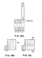
- Figure 16A shows a head structure used in this embodiment.
- the number of nozzles for ejecting the black ink is not less than twice as many as the number of color nozzles, so that when the data contain only black data, the black nozzles are fully used to raise the printing speed.
- the number of black nozzles to be actuated is reduced in order to suppress the bleeding among the black dots, and in the case of the black and color printing, at least one scan black is given.
- Figure 16B schematically shows the printing of black data only
- Figure 16C schematically shows the printing of black and chromatic data in mixture.
- the boundary stripe tends to occur in the case of the color printing since the amount of the ink is large on the recording material.
- the black printing is carried out prior to the color printing with the nozzles structure in this embodiment. Therefore, at the time of the color printing, the black ink printing has already finished, and the black ink has started fixing on the recording material. For this reason, the black ink is not influential to the boundary stripe.
- the dot count is not carried out for the black ink, accordingly. But, the color inks (cyan, magenta and yellow) only are subjected to the dot count, for the boundary processing.
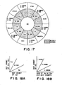
- the hue direction represents the position on the outermost circumference in Figure 17, that is, the primary color, the secondary color or the intermediate.
- the abscissas are dot counts of the primary color
- the ordinates are dot counts of the secondary color.
- the classification for the primary color, the secondary color and the indicated color is as follows. The comparison is made between the dot count of the primary color divided by 2 and the dot count of the secondary color. If the former is larger, the hue thereof is classified into the primary color.
- the comparison is made between the dot count of the primary color and the dot count of the secondary color divided by 2. If the latter is larger, the hue thereof is classified into the secondary color. Otherwise, it is classified into the intermediate hue.
- the chromaticity direction that is, whether it is close to the center, close to the circumference or in the middle, is discriminated.
- Figure 18B shows a sum of dot counts of the primary color and secondary color vs. dot count of the UC (ordinates).
- the classification in the chromaticity direction is as follows. The comparison is made between the sum of the dot counts of the primary color and the secondary color divided by 2 and the dot count of the UC, and if the former is larger, the chromaticity is closest to the circumference, and the area is determined as the color area of the dot count area.
- the comparison is made between the sum of the dot counts of the primary color and the secondary color divided by 2 and the dot count of UC. If the latter is larger, the comparison is made between the dot count of UC divided by 2 and the sun of the dot counts of the primary color and the secondary color, and if the former is larger, the chromaticity is closest to the center, and the area is determined as the color area of the dot count area. Otherwise, the intermediate area is selected.
- the color area is finely divided, the differences in the degree of the boundary stripe can be finely dealt with, and the behavior of each of the ink can be taken into account.
- Figures 19A-F show an example of a combination of the rank graphs used in this embodiment.
- the thinning ranks can be designated for 7 areas (cyan, magenta, yellow, blue, green, red and UC) of the color areas shown in Figure 17, for the respective inks.
- the thinning rank graph for the intermediate areas other than those, are calculated from the graphs in the 7 areas. By doing so, the number of data of the rank graphs can be reduced.
- an average between the primary color and the secondary color is taken for the intermediate area in the hue direction, and a higher one of the thinning ranks of the high chromaticity and the low chromaticity, for the intermediate area in the chromaticity direction.
- the thinning rank graphs for the blue color area are actually used when the result of the color area discrimination designates the dot count area of blue color. This is taken out, and is shown in Figures 19A-F. Similarly, the rank graph heads for the red color area is shown in Figures 20A-F.
- the thinning rank to be used in the SMS thinning process is determined.
- the thinning rank graphs are not designated for all the divided color areas, but the basic ones are designated, and the graph is calculated out for the intermediated areas, so that amount of the data can be reduced.
- the SMS thinning process is carried out for the unit areas, similarly to the first embodiment. These processes are carried out for one band, and then, the printing for one scan is carried out.
- the printing is carried out using the cyan ink and the magenta ink, and at the point where the blue is maximum, the cyan and magenta data are indicative of solid print (maximum duty data), that is, level 512 in this example.
- the color area of the unit area is blue, and in order to suppress the production of the boundary stripe, rank 5 thinning (Figure 19A) which is high is effected to the cyan lower, and rank 6 ( Figure 19C) which is also high is effected to the magenta lower.
- Figure 20 illustrates the process in which the printing of a gradation from white, red to UC. Then, the cyan ink is first started to be used at the point of change from the red at the maximum to the UC. At this point, the data of the magenta and yellow are of maximum duty, that is 512, which is equal to the data where the color changes from blue to black in the case of the gradation white-blue-black, and the color area is red. Referring to Figure 20, rank 3 thinning is effected for the cyan lower ( Figure 20 (a)), and rank 5 thinning is effected for magenta lower ( Figure 20 (c)).
- the cyan dot density is not large (sparse) at the beginning of the data, and therefore, the relatively low rate (rank 3) thinning is executed for the cyan color.
- the cyan dot void is not conspicuous. If, on the contrary, the thinning Table of Figure 19 is used without consideration to the color area, the high rate thinning, namely, rank 5 thinning is effected to the cyan lower, and therefore, the cyan dot void is conspicuous.
- the used dot count unit area is 16 dots x16 raster lines (sub-scan direction).
- the size is not limiting, and the size of the unit area is properly determined by one skilled in the art in consideration of the conspicuousness of the boundary stripe, the load added by the data process, the output resolution or the like.
- the area in which the dot counting is executed is astride the boundary area between the adjacent bands, as shown in Figure 5, for example, in the first and second embodiments, but the present invention is not limited to this example.
- the dot counting may be carried out only for the bottom portion of the prior scanning, or it may be carried out for the top portion of the next scanning.
- the position where the SMS thinning process is carried out is not limited to the bottom end portion of the prior scan, but it may be the top end of the later scan, or both, that is, astride the boundary between adjacent bands.
- dot count area and SMS thinning process area can be selected on the basis of combination of the recording material and the recording ink. For this reason, the dot count area and/or the SMS is changeable responding to the recording material used.
- the number of color areas with the above is two in this embodiment, but the number is not limiting.
- the one path printing is the basic mode, since in that mode, the boundary stripe production is most conspicuous.
- the boundary stripe is more or less produced in the multi-path printing.
- the thinning process is preferable in the multi-path printing with the thinning rank graph corresponding to the number of paths for the multi-path mode.
- the boundary stripe is caused mainly by the bleeding of the recording ink on the recording material, and therefore, the boundary stripe is more conspicuous under the high temperature and high humidity ambience since then the degree of the recording ink bleeding is higher.
- plurality of threshold levels for switching the thinning rank graph and the thinning area are provided which are selectable depending on the ambient conditions.
- the recording ink used are cyan, magenta, yellow and black inks.
- the present invention is applicable to the system using so-called photo-ink which is diluted regular ink.
- the data relating to the amount of ejection for each of inks are binary data, but the present invention is not limited to this.
- the data may be R, B, G multi-level data, if the data correspondent to the amount of the ink ejected.
- the amount of the ink is not limited to the reduction by thinning the data, but may be multiplication of reduction coefficients to the multi-level data.
- the ejection amount of the ink may be reduced using a look-up table at the time of color conversion from R, G, B to Y, M, C, K, and this example will be described as a third embodiment.
- the use is made with a recording system in which a plurality of recording heads print with recording ink on a recording material to form an image, similarly to the first embodiment.
- the description will be made as to an example of a boundary process in the case of multi-level data of R, G, B as the data relating to the ejection amounts of the inks.
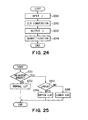
- FIG 24 is a flowchart of an example of the color processing method.
- the color processing is a process of producing printable data for a printer from the data received from personal computer or the like, and in this embodiment, the RGB 256 tone gradation (8 bit) data (input data for a four color (CMYK) printer) to CMYK binary output data.
- RGB 256 tone gradation (8 bit) data input data for a four color (CMYK) printer
- an input &c& correction process is carried out at step S241.
- the curve is called also "video curve", and the correction is is carried out in view of a correction curve as in the case of presentation on a display for example.
- the input and output are made on the basis of RGB 256 tone gradation data.
- the color conversion executed in the step S242 is dependent on whether the output image is a graphic image or photographic image, and it is also called preliminary step.
- the input and output data are RGB 256 tone gradation data.
- the RGB 256 tone gradation data are converted to CMYK256 tone gradation data conversion.
- a look-up table is used which determines the output from the input in 1 to 1 correspondence.
- CMYK256 tone gradation data In order to make the CMYK256 tone gradation data printable, the data are converted or quantized to CMYK binary (3 or 4 level) data. This is the end of the color processing.
- FIG. 25 is a flowchart of the boundary process in the multi-level data.
- the discrimination is made as to whether or not it is adjacent the boundary area (whether or not it is in the four raster lines at the sheet discharge side in the boundary in this embodiment) (step S251). If not, the conversion is normal, that is, the conversion is carried out using the normal look-up table. If it is adjacent the boundary area, a further discrimination is made as to whether it is UPPER or LOWER ( Figure 5) (step S253), and the conversion to the CMYK256 tone gradation data is carried out using a look-up table in accordance with the result of the further discrimination (steps S254 and 255).
- a total sum detecting circuit 261-263 determines total sums of data amounts of respective colors in a predetermined area adjacent the boundary (dot count area or 16 x16 dot area in Embodiment 1), and on the basis of the total sums, the color area of the predetermined area is discriminated by a color area discrimination circuit 264 ( Figure 17).
- the look-up tables 265 are prepared, and one of the look-up tables 265 is selected in accordance with the color area discriminated by the color area discrimination circuit 264, so that ejection amounts in the boundary area can be reduced in accordance with the color area together with the data conversion from the RGB to the CMYK data.
- the data conversion is executed not only on the basis of the information from each of the pixels but also on the basis of the data amounts of the dot count area in a certain area, and therefore, more effective and proper boundary process is accomplished.
- the three-dimensional LUT265 is not only on the basis of the color area but also on the basis of the total sums of the respective colors provided by the total sum detecting circuit 261-263.
- the color area is relative information covering the colors, and therefore, use of the total sums of the amounts of the date of the respective color, which are absolute information, is desirable to obtain the degree of generation of the bleeding and the stripe at the boundary.
- the boundary processing is carried out. This is preferable since then a better value can be selected for each of all of the input data, and therefore, the effect of the boundary processing is enhanced. Additionally, the processing is carried out before the quantization, and therefore, unlike the processing skipping the dots as with the processing after the binarization. Therefore, the RGB multi-level data is converted during the multi-level data generation step, and no dot is skipped, thus accomplishing natural prints.
- boundary processing is carried out at the time of the color conversion from the RGB to the YMCK, and the conversion table can be saved, and the processing is efficient.
- the boundary processing may be carried out not at the time of the color conversion, but after the color conversion, that is, after the conversion to the YMCK multi-level data.
- the boundary processing can be effected to the multi-level data.
- the multi-level data have been described as being 256 tone gradation, but the number of tone gradation levels is not limited to this example.
- the boundary processing in the ink jet recording apparatus has been taken, but the processing may be carried out by the host computer (PC), that is, by the printer driver side.
- the data having been subjected to the boundary processing is supplied to the ink jet recording apparatus from the host computer.
- the present invention is very effective when used with an ink jet recording system, in particular, when used with an ink jet recording head which comprises a means for generating thermal energy (for example, electrothermal transducer, or a laser) used for ejecting ink, and in which the state of ink is changed by the thermal energy, and also a recording apparatus employing such an ink jet recording head.
- thermal energy for example, electrothermal transducer, or a laser
- the present invention is particularly suitably usable in an ink jet recording head and recording apparatus wherein thermal energy by an electrothermal transducer, laser beam or the like is used to cause a change of state of the ink to eject or discharge the ink. This is because the high density of the picture elements and the high resolution of the recording are possible.
- the typical structure and the operational principle are preferably the ones disclosed in U.S. Patent Nos. 4,723,129 and 4,740,796 .
- the principle and structure are applicable to a so-called on-demand type recording system and a continuous type recording system. Particularly, however, it is suitable for the on-demand type because the principle is such that at least one driving signal is applied to an electrothermal transducer disposed on a liquid (ink) retaining sheet or liquid passage, the driving signal being enough to provide such a quick temperature rise beyond a departure from nucleation boiling point, by which the thermal energy is provided by the electrothermal transducer to produce film boiling on the heating portion of the recording head, whereby a bubble can be formed in the liquid (ink) corresponding to each of the driving signals.
- the liquid (ink) is ejected through an ejection outlet to produce at least one droplet.
- the driving signal is preferably in the form of a pulse, because the development and contraction of the bubble can be effected instantaneously, and therefore, the liquid (ink) is ejected with quick response.
- the driving signal in the form of the pulse is preferably such as disclosed in U.S. Patents Nos. 4,463,359 and 4,345,262 .
- the temperature increasing rate of the heating surface is preferably such as disclosed in U.S. Patent No. 4,313,124 .
- the structure of the recording head may be as shown in U.S. Patent Nos. 4,558,333 and 4,459,600 wherein the heating portion is disposed at a bent portion, as well as the structure of the combination of the ejection outlet, liquid passage and the electrothermal transducer as disclosed in the above-mentioned patents.
- the present invention is applicable to the structure disclosed in Japanese Laid-Open Patent Application No. 123670/1984 wherein a common slit is used as the ejection outlet for plural electrothermal transducers, and to the structure disclosed in Japanese Laid-Open Patent Application No. 138461/1984 wherein an opening for absorbing pressure wave of the thermal energy is formed corresponding to the ejecting portion. This is because the present invention is effective to perform the recording operation with certainty and at high efficiency irrespective of the type of the recording head.
- the present invention is applicable to a serial type recording head wherein the recording head is fixed on the main assembly, to a replaceable chip type recording head which is connected electrically with the main apparatus and can be supplied with the ink when it is mounted in the main assembly, or to a cartridge type recording head having an integral ink container.
- the provisions of the recovery means and/or the auxiliary means for the preliminary operation are preferable, because they can further stabilize the effects of the present invention.
- preliminary heating means which may be the electrothermal transducer, an additional heating element or a combination thereof.
- means for effecting preliminary ejection (not for the recording operation) can stabilize the recording operation.
- the recording head mountable may be a single corresponding to a single color ink, or may be plural corresponding to the plurality of ink materials having different recording color or density.
- the present invention is effectively applicable to an apparatus having at least one of a monochromatic mode mainly with black, a multi-color mode with different color ink materials and/or a full-color mode using the mixture of the colors, which may be an integrally formed recording unit or a combination of plural recording heads.
- the ink has been liquid. It may be, however, an ink material which is solidified below the room temperature but liquefied at the room temperature. Since the ink is controlled within the temperature not lower than 30 SUPo/SUPC and not higher than 70 SUPo /SUPC to stabilize the viscosity of the ink to provide the stabilized ejection in usual recording apparatus of this type, the ink may be such that it is liquid within the temperature range when the recording signal is the present invention is applicable to other types of ink. In one of them, the temperature rise due to the thermal energy is positively prevented by consuming it for the state change of the ink from the solid state to the liquid state. Another ink material is solidified when it is left, to prevent the evaporation of the ink.
- the ink is liquefied, and the liquefied ink may be ejected.
- Another ink material may start to be solidified at the time when it reaches the recording material.
- the present invention is also applicable to such an ink material as is liquefied by the application of the thermal energy.
- Such an ink material may be retained as a liquid or solid material in through holes or recesses formed in a porous sheet as disclosed in Japanese Laid-Open Patent Application No. 56847/1979 and Japanese Laid-Open Patent Application No. 71260/1985 .
- the sheet is faced to the electrothermal transducers.
- the most effective one for the ink materials described above is the film boiling system.
- the ink jet recording apparatus may be used as an output terminal of an information processing apparatus such as computer or the like, as a copying apparatus combined with an image reader or the like, or as a facsimile machine having information sending and receiving functions.
- the unit area in which the ink ejection amount is counted is astride the boundary between the adjacent bands, and the situation at the boundary can be properly predicted.
- the thinning area can be properly selected, and therefore, the production of the banding can be effectively suppressed.
Abstract
Description
- The present invention relates to an ink jet recording method, a recording device and a data processing method in which high quality images can be formed on a recording material with suppressed banding nonuniformly, more particularly to the ink jet recording method, the recording device and the data processing method in which the recording is carried out through one-path or multi-path printing.
- The present invention is applicable to any equipment using as the recording material, paper, textile, leather, nonwoven fabric, OHP sheet, metal or the like. More particularly, the present invention is applicable to a printer, copying machine, facsimile machine or another office equipment, industrial manufacturing machines or the like.
- As regards the recording on the recording material using the recording apparatus, the demand for high-speed printing picks up. In order to increase the printing speed, it is one of the methods to refuse the number of paths in the multi-path printing which has been proposed to accomplish formations of high quality images. Here, the number of paths is the number of scans of the carriage required to complete one line of printing.
- Since the number of ejection outlets of the recording head is limited, the amount of the sheet feed for units can is smaller if the number of paths is larger. On the other hand, the sheet feeding distance per unit can can be increased by reducing the number of paths. For example, in the case that printing is carried out in the two-path mode, the speed can simply be doubled by changing it to one-path printing. That is, the reduction of the number of paths reduces the number of scans to cover a predetermined area (one sheet, for example), and increases the distance of sheet feed, so that time required for printing is shortened.
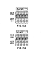
- In the case that recording ahead having a plurality of ejection outlets for ejecting the recording liquid (ink) scans the recording material in the direction perpendicular to the direction in which ejection outlets are arranged, an image is formed in an image area in the form of a band by one scan of the recording head, as shown in Figure 21.
- Thus, in the case of the one-path printing, the duty (ratio) of the recording ink ejected per unit time is larger than when the one band area is printed through a plurality of scans (multi-path printing). Therefore, the production of the black stripe between the adjacent bands (paths) is remarkable at the portions where the printing duty is high, although it is different depending on the nature of the recording material and the recording liquid.
- The problem is more significant in the case of lateral arrangement of the recording heads in which cyan, magenta and yellow recording heads or the like are arranged in the main scan direction. This is because the boundaries appear at the same position. Figure 6 schematically shows the laterally arranged recording heads.
- The black stripe appearing at the adjacent bands is called connecting stripe, spending or the like. It might deteriorate the image to such an extent that image is practically unsatisfactory.
- Therefore, a method of avoiding the banding in one-path printing, thus improving the image quality.
- For example,
Japanese Laid-open Patent Application 11-188898 - However, in the conventional method, the accuracy of the suppression of the banding in the case of plain paper or the like with which the banding tends to occur.
- Accordingly, it is a principal object of the present invention to provide an ink jet recording apparatus, a recording method and a data processing method with which the banding is suppressed even in the case of one-path printing.
- According to an aspect of the present invention, there is provided the ink jet recording apparatus according to
claim 1. - According to another aspect of the present invention, there is provided the data processing method according to claim 20 for effecting recording on a recording material by ejecting a plurality of inks with relative scanning movement between a recording head and the recording material.
- According to a further aspect of the present invention, there is provided the ink jet recording method according to
claim 24. - With the structure according to the invention, a discrimination is made on the basis of the number of recording data (the number of dots to be printed) adjacent the boundary area as to the color area (hue and chromaticity) of a unit area (noting region), and the thinning rank is determined for each of the used inks and for each of the printing positions in accordance with the discriminated color area. By the thinning process for each of the inks using the thinning rank, the boundary stripe produced between the bands in a single path printing, can be suppressed.
- These and other objects, features and advantages of the present invention will become more apparent upon a consideration of the following description of the preferred embodiments of the present invention taken in conjunction with the accompanying drawings.
-
- Figure 1 is a partly broken perspective view of an ink jet recording apparatus according to an embodiment of the present invention.
- Figure 2 is a schematic perspective view of a major part of a recording head used in the apparatus of Figure 1.
- Figure 3 is a block diagram of a control circuit for an ink jet printing apparatus according to an embodiment of the present invention.
- Figure 4 is a flow chart of process steps according to a first embodiment of the present invention.
- Figures 5A and 5B illustrate an area for which a dot counting operation of the print data is carried out and an area in which the thinning is executed.
- Figure 6 is a schematic view illustrating a structure of the recording head according to the first embodiment of the present invention.
- Figure 7 is a flow chart of color area discrimination steps according to the first embodiment of the present invention.
- Figure 8 is a schematic illustration of an example of a dot count in a unit area according to the first embodiment of the present invention.
- Figure 9 shows an example of the sections of the color areas according to the first embodiment of the present invention.
- Figures 10A and 10B show an example of a thinning rank graph according to the first embodiment of the present invention.
- Figure 11 shows an example of the count in a SMS process according to the first embodiment of the present invention.
- Figures 12A to F show an example of a thinning rank graph according to the first embodiment of the present invention.
- Figures 13A and B illustrate a mechanism of ink bleeding occurring at the connection between adjacent bands.
- Figures 14A-D illustrate a print data processing using the SMS process according to the first embodiment of the present invention.
- Figures 15A-F illustrate a print data processing using the SMS process according to the first embodiment of the present invention.
- Figures 16A-C are schematically illustration of a recording head according to a second embodiment of the present invention.
- Figure 17 shows an example of the sections of the color areas according to the second embodiment of the present invention.
- Figures 18A and B illustrate an example of a dividing method in a color area according to the second embodiment of the present invention.
- Figures 19A to F show an example of a thinning rank graph according to the second embodiment of the present invention.
- Figures 20A to F show an example of a thinning rank graph according to the second embodiment of the present invention.
- Figure 21 is a schematic view illustrating a band and boundary.
- Figures 22A-E illustrate a thinning process using a mask according to an embodiment of the present invention.
- Figures 23A and 23B are schematic illustrations of behavior of the recording ink on the recording material.
- Figure 24 is a flow chart of an example of the color processing method according to a third embodiment of the present invention.
- Figure 25 is a flow chart of process steps according to a first embodiment of the present invention.
- Figure 26 is a block diagram of a boundary process according to the third embodiment of the present invention.
- The preferred embodiments of the present invention will be described taking a serial printer having a plurality of recording heads for instance.
- In this embodiment of the present invention, a neighborhood of a connecting or boundary portion of the data of one band is divided into a plurality of unit areas, and the number of dots for each of the unit areas are counted, and then, the color area of a noted area is discriminated on the basis of the dot counts for the respective colors. A thinning rank for each thinning process area is determined for each color on the basis of a predetermined thinning rank graph and a dot count (or printing duty) for each unit area provided by a sum of the dot counts for each color in the color area.
- This will be further described.
- As shown in Figures 5A, B, the area in which the thinning process is executed is several raster areas (4 rasters, for example) at a sheet inlet side (upstream side with respect to the feeding direction of the sheet) in one scan area to be printed. It is noted that thinning beforehand, that is, the thinning in the sheet feeding side is preferable than the other, since the margin relative to the recording material is large. By doing so, a larger number of recording materials can be supported than in the case that thinning processes effected at the sheet discharging side on the basis of one parameter.
- When the thinning process is effected over several raster areas, the degrees (rank graph, in this example) of thinning can be independently selected for each raster areas or for each several raster areas, by which, for example, the degree of thinning can be made higher in the area closer to the boundary than in the other areas, thus improving the accuracy of the thinning process.
- The area in which the dots are counted, as shown in Figure 5A, is 16 dot x 16 raster areas (dot) astride the boundary area. Since the area in which the dots are counted is larger than the thinning area so that print data of the bands astride the boundary are counted, the circumstances influential to the bleeding at the boundary can be taken into consideration.
- The thinning process for the print data in this embodiment is a so-called SMS (sequential multi-scan) type. Other thinning processing methods include a type using a pattern mask and an error diffusion (ED) type.
- However, in the method using the pattern mask (Figure 22A-E), a mask of staggered arrangement is used for example (pixel data of white parts are skipped), and when the print data having the same amounts of ink ejections as shown in Figure 22B. C, are processed, the data after the process are shown in Figures 22D and 22E, and the print data at the "x" portions are skipped. As will be understood from the two Figures, the thinning mask and the print data interfere in the case of the data of the same ejection amount (duty), depending on the arrangement of the print data, and therefore, the amount of thinning cannot be controlled in some cases.
- As to the use of the error diffusion type, the following is an example.
- If the pixel for which the quantitized image data process is to be effected, contains the data to be printed, a multi-level value is assigned in accordance with a predetermined nozzle correction value:
- Errors of the peripheral pixels are added:
- After comparison with a predetermined threshold, it is determined whether or not the print data is skipped or not:
- The error resulting from the determination is calculated.
- The error is assigned to a peripheral pixel or pixels: and
- If the pixel for which the quantitized image data process is to be effected, does not contain, the errors in the peripheral areas are obtained and then are reassigned to the peripheral areas.
- After comparison with a predetermined threshold, it is determined whether or not the print data is skipped or not:
- It is predicted that in the case of 1 path printing, the print data process requires too long time, since the recent high density nozzle head has many nozzles. If the printing operation is interrupted waiting for the data processing, the carriage has to stop with the result of low throughput which is against the purpose of use of one-path printing.
- In view of this, in this embodiment, the use is made with a so-called SMS thinning process to accomplish both of the uniformation of the amount of thinning and the high speed processing. In the SMS thinning process, whenever there is a printing datum, the count designated by the counter (register) (particular bit; MSB, for example), and if it is "1", the print data is not skipped (printed), and on the other hand, if the counter value is "0", the print data is skipped (thinned) (not printed). The counter is shifted to the right (bit shift). When the counter is shifted to the right side end, it returns to the left end (cyclic shifting).
- This is repeated for each of the print data to determine the dots to be skipped. As described in the foregoing, the determination whether the thinning is to be detected, is carried out only for the dots having the print data, and therefore synchronism with the pattern of the print data does not occur.
- The coloring at a marginal area of printed dot is different if the order of prints of inks on the recording material is different. Figures 23A, B schematically show an example of penetration of the recording ink into the recording material. The behavior of penetration of the recording ink is different depending on the material of the recording ink, the recording material, the ambient conditions, differences in the time interval between prints or the like, though.
- Here, the later printed
recording ink 232 sink under the first printedrecording ink 231. In this manner, the recording inks printed onto the same position on the recording material do not mix with each other, usually, and the coloring occurs with the situation shown in Figure 23A. It will be understood that at theend 233 of the printing indicated by a circle in Figure 23B, has a coloring which is different from that inside 234 in the inside. More particularly, the later printed ink has a stronger coloring than the first printed ink. This functions also to worsen the connecting seam at the boundary. Therefore, even if the same thinning rate is used for the recording ink to be first printed and the recording ink to be later printed, the differences in the coloring at the marginal area are not avoided. Therefore, in this embodiment, the thinning rate is determined in consideration of the order of depositions of the ink onto the recording material. - Figure 10A shows an example of a rank graph for a thinning to be used for determining the thinning rate in this embodiment. The thinning rank graph gives ranks corresponding to the dot counts in the dot count area for each of the inks which is subjected to the thinning process.
- The thinning rank graph is designated on the basis of three values, namely, a start dot number, the dot interval and the MAX rank. The levels of the thinning ranks are determined beforehand. In this embodiment, for example, there are nine levels, namely, 0%, 12.5%, 25%, 37.5%, 50%, 62.5%, 75%, 87.5% and 100%.
- The respective parameters will be described. The start dot number is the total dot count at which the use of the thinning rate12.5% (thinning rank 1) is started. The dot interval is the dot count before the next thinning rate (25% if the current thinning rate is 12.5%), that is, the range of the dot count using the same thinning rate. MAX rank is the maximum thinning rate, that is, no thinning rate beyond that is not selectable. If the thinning rate reaches the MAX rank, the thinning rate is not raised, and the MAX rank thinning rate is maintained even if the dot count reaches the number corresponding to the dot interval.
- Because of this system using the three parameters, one thinning line in the rank graph can be expressed by 1 bite ((8 bits); one component (8 levels) for the start dot number, one component for the duct interval (8 levels), and one component (4 levels) for the
MAX rank 1. - In order to enhance the resolving power for each of the parameter, the number of bits may be increased. Alternatively, the number of bits is not changed, but a common offset value may be given commonly to the start dot number, the dot interval and the MAX rank, by which the parameters can be more accurately set.
- In this manner, the amount of the data required for setting the thinning rank graph. The reduction of the amount of the data is particularly preferable in this embodiment. The reason is as follows. In order to carry out the connecting processing as in this embodiment in the quick printing mode as in the one-path printing mode, use of hardware prefers to the use of software. This is because the speed of the data processing using the software is not enough to catch up with the printing speed. It is preferable to use hardware such as a gate array. In this case, the number of required data is directly influential to the number of gates, and therefore, less number of data is preferable from the standpoint of the circuit scale.
- Figure 10B shows another example of the thinning rank. This example is particularly effective in such a case that inclination of the thinning rank line is desirably changed.
- In addition to the three parameters required to express the thinning ranks, there are provided the change dot number indicative of the start point of the inclination change and the
dot interval 2 for determining the new inclination, in this example. With use of such parameters, more accurate control is accomplished. - Depending on the relationship between the used ink and the recording material, the behavior on the recording material after the actual printing is different, and the conspicuousness of the boundary line and the effectiveness to the boundary line after the thinning process is also different.
- For example, in the case of a gradation from white to blue and UC (under color, mixture of YMC), the printing is carried out using the cyan ink and the magenta ink where the color is changing toward blue, and at the position where the blue reaches the maximum level, the solid printing occurs for the cyan and magenta colors (the data of maximum duty). In the state, in order to reduce or suppress the boundary line, a certain high degree of thinning process is effected to the cyan and magenta colors.
- Suppose that gradation from white to red and UC using the same thinning parameters. Then, the cyan ink is first started to be used at the point of change from the red at the maximum to the UC. At this point, the data for the magenta have the maximum duty level which is the same as the position where the gradation changes from the blue to the black in the foregoing white - blue - black gradation example, and therefore, the highly thinning rate used for the cyan and magenta colors in the foregoing example, is used in this example. These results in that large percentage of cyan dots are removed in the area where the cyan dots are sparse, and therefore, lack of cyan dots is conspicuous.
- Thus, it is desirable in the connecting process in the boundary area in the formation of color images that in addition to the conventionally used total amount of the ink to be applied to the unit area adjacent to the end portion, the information relating to the hue and the chromaticity of the unit area and the information as to which recording ink is used for printing is obtained, and that thinning rate is selectable on the basis of these pieces of information. In order to accomplish this, in this embodiment, the discrimination is made as to the hue and the chromaticity of the noting area (unit area) from the dot count for each color. In the following, the term color area is used as a word covering both of the hue and the chromaticity in combination.
- In the foregoing embodiment, the color area of the noting area is discriminated from the number of recording data (the number of dots to be printed) in the neighborhood of the boundary area between adjacent bands, and in accordance with the color area, the thinning rank (the degree of thinning) can be selected for each of the used ink and the recording positions. Using the selected thinning rank, the thinning process is effected to each of the inks, so that conspicuousness of the boundary line between adjacent bands can be suppressed in the one-path printing.
- The description will be made as to Details of this embodiment. The same reference numerals are assigned to the elements having the corresponding functions in the Figures.
- The first embodiment creates to a recording system in which the plurality of recording heads are used to effect recording on the recording material with recording ink.
- Figure 1 is a schematic perspective view of a major part of an ink jet recording apparatus according to the first embodiment of the present invention. In Figure 1, a plurality of (3, in this embodiment)
head cartridges carriage 2. Each of thecartridges 1A-1C is provided with connector for receiving a signal for driving the recording head. In the following descriptions, when all the recording means 1A-1C or anyone on them are designated, the term "recording means" (recording head or head cartridge) is used. - The
respective cartridges 1 function to print different color inks. Therefore, the ink containers contain cyan, magenta, yellow inks and so on which have different colors. Each of the recording means 1 is exchangeably positioned and carried on thecarriage 2 thecarriage 2 is provided with a connector holder (electrical connecting portion) for transmission the driving signal or the like to each of the recording means 1 through the connector. - The
carriage 2 is supported and guided on a guidingshaft 3 extending in the main scan direction in the main assembly of the apparatus, and is movable in the main scanning direction. Thecarriage 2 is driven and controlled by the main-scanning motor 4 through amotor pulley 5, a drivenpulley 6 and atiming belt 7. Therecording material 8 such as a sheet of paper, thin plastic resin sheet or the like is fed through a recording position where the recording material is faced to the ejection outlet side surface of therecording head 1 by the rotation of the two pairs of feeding rollers. Therecording material 8 is supported on a platen (unshown) at the back side so as to provide a flat recording surface in the recording position. In this case, each of thecartridges 1 carried on thecarriage 2 has the ejection outlet side surface which is projected downwardly from thecarriage 2, and is supported to be parallel with therecording material 8 between the pairs of feeding rollers. - The
recording head 1 is in the form of an ink jet recording means which ejects the ink using the thermal energy, and is provided with electrothermal transducers for generating thermal energy. In therecording head 1, film boiling is caused by the thermal energy applied by the electrothermal transducer. By the growth and collapse of the bubble created by the film boiling, a pressured change is produced so as to eject the ink. Figure 6 illustrates a structure of nozzles of the recording heads. - Figure 2 is a schematic perspective view illustrating a major part of an
ink ejection portion 13 of therecording head 1. As shown in Figure 2, theejection side surface 21 is faced to therecording material 8 with a gap of approx. 0.5-2 mm, and is provided with a plurality of (256 in this embodiment)ejection outlets 22 at a predetermined intervals (360dpi in this embodiment). The recording head further includes acommon liquid chamber 23 andflow paths 24 for fluid communication between thecommon liquid chamber 23 and theejection outlets 22. Each of theflow paths 24 is provided of the wall constituting the path with an electrothermal transducer 25 (heat generating resistor, for example) which is effected to generate energy corresponding to the amount of the ink ejection. In this embodiment, the recording heads 1 are carried on thecarriage 2 in the manner that saidejection outlets 22 are arranged in the direction crossing with the scanning direction of thecarriage 2. Theelectrothermal transducers 25 corresponding to the image signals or to the ejection signals are actuated (energized) to cause a film boiling in the ink in theflow path 24, and the pressure produced by the boiling functions to eject the ink through theejection outlet 22. - Figure 3 schematically illustrates a control circuit used in the ink jet printing apparatus shown in Figure 1.
- In Figure 3, a
controller 100 constitutes a main controller and includes a CPU101 in the form of a microcomputer, aROM 103 storing a program, a table, fixed data or the like, and aRAM 105 providing an area for conversion of the image data and a working area. Thehost apparatus 110 is the supply source of the image data, and it may be a computer which produces and processes image data or the like relating to the printing, or it may be a reader portion for reading images. The image data, the command, the status signal and the like are supplied to or receive from thecontroller 100 through an interface (I/F). - An operating portion 120 include a group of switches operable by the operator, a
main switch 122, aprint start switch 124, arecovery switch 126 for actuating suction recovery operation. - A
head driver 140 actuates theejection heaters 25 of theprint head 1 in accordance with the print data or the like. Thehead driver 140 includes a shift register for aligning the print data corresponding to the positions of theejection heater 25, a latching circuit for effecting latching at proper timing, a logic circuit element for actuating the ejection heater in synchronism with the drive timing signal, a timing setting portion for properly setting the actuation timing for correct positioning of the dot formation. - The
print head 1 is provided with a sub-heater 142. The sub-heater 142 functions to control the temperature in order to stabilize the ejection property of the ink, it may be formed on the print head substrate simultaneously with theejection heater 25, or it may be mounted to the main assembly of the print head or the head cartridge. - The motor is to drive the main-
scanning motor 152, and thesub-scan motor 162 is for feeding the print medium 8 (sub-scan), themotor driver 150 is a driver for the motor. - Figure 4 is a flow chart showing operations from the reception of the amount of the print data corresponding to one scan to the end of the print data process.
- At step S1, the amount of the print data required for printing one scan for each of the different color inks. For the printing of one scan, the data for one band is necessary, and the data in the dot count area of the next band are required as well. Here, one band is a printing area printed by one carriage scanning operation.
- After the print data is received, a step S2 executes the dot count operation, a step S3 executes the color area discrimination, a step S4 executes the thinning rank determining operation, and a step S5 effects the SMS thinning process, for each of the unit areas, that is, each of 16 dots x 16 dots raster areas shown in Figure 5. At step S6, the foregoing process is repeated until one band is covered. The description will be made as to the respective processes.
- In this embodiment, the area subjected to the dot count operation is a width corresponding to the 16 raster lines including the connecting portions between adjacent bands.
- The dot count operation is carried out for all of the recording inks carried on the recording device of this embodiment, more particularly, the dot count operation is carried out for the binary data for the cyan, magenta and yellow colors. A sum of the dot counts of them is the dot count (or the total dot count) as a result of the dot count operation.
- Here, the event that dot count is "1" means that one dot is present in one pixel, and the event that dot count is "2" means that two dots are present in one pixel.
- The dot count operation is carried out in the divided areas adjacent to the boundary between adjacent bands, and the size of the area is 16 raster lines in the sheet discharging direction, and 16 dots in the scanning direction of the carriage (unit area for the dot count). Therefore, the maximum of the total dot count value is 16 (raster) x 16 (dots) x 3 (color number) = 768.
- In the process of this embodiment, and the thinning rank is determined from the total dot count obtained by the dot count step, and the SMS thinning process is carried out. It is possible to obtain relative information indicative of the relative relation among the amounts of the inks printed in the unit areas, from the dot counts for each of the colors, and the discrimination is made as to the color area (hue and chromaticity) of the unit area from the relative information.
- Such a process is repeated for one band until all of the bands corresponding to one page are subjected to the process, so that print data are generated.
- Therefore, in the case of 360dpi A4 full scanning (8in.), 180 calculations (360 (dpi) x 8 (inch) / 16= 180) are to be carried out.
- In this embodiment, the total dot count is the simple total sum of the dot counts of the cyan, magenta and yellow colors, but the counts may be weighted depending on the colors when the degrees of influence to the production of the boundary strike are not uniform. For example, in a case, the conspicuousness of the boundary line is worsened by the yellow ink, then, the dot count for the yellow color may be weighted, for example, the dot count of the yellow is multiplied by 1.2. In another case, the ejection amounts are different depending on colors (for example, in the amount of the ejected red ink is larger than the other, then, this is taken into account.
- Using the dot count process as described in the foregoing, the data processing may be carried out only for the small areas which is adjacent to the boundary between bands (that is, the end portion of the array of the nozzles. Therefore, the load required by the process is small, such that even in the case that time period which can be given to the process is short as in the case of one path printing.
- The description will be made as to the reason why the 16 dots x 16 dots area astride the boundary between the adjacent bands is selected as the unit area in which the dot count operation is carried out.
- In this case, the maximum value of the total dot counts is 16 x16 x 3 (the number of colors) = 768. In order to form 1 band, 180 calculations are required in the case of 360dpi, as described hereinbefore, and in the case of 600dpi, A4 full scanning (approx. 8in.), the number of calculations is 600 (dpi) x 8 (inch) / 16= 300. More specifically, as shown in Figure 5A, the dot count operation is sequentially carried out for each of the dot count unit areas for all of the range determined by the set length, and the corporations are carried out for all of the dot count unit areas, by which the dot count operation for 1 band is completed.
- By using the areas astride the boundary between the adjacent bands in this manner, the state of print dots before and after the boundary can be known. More particularly, it is possible to discriminate whether or not the ink ejections tend to produce the boundary line, and therefore, a high precision boundary processing is accomplished. When the dot count operation is carried out only for the areas within one band, it is possible to predict the degree of ink bleeding attributable for the production of stripes within the band, but it is not possible to predict the degree of influence to the next band. The production of the boundary line or stripe is dependent on the amount of the ink adjacent the boundary between the adjacent bands.
- For example, when a certain quantity of ink is in the next band, the boundaries stripe is suppressed due to the ink bleeding. When the amount of the ink is small, the possibility of the production of the stripe is not high, although the ink bleeding may occur.
- Referring to Figures 13A, B, the description will be made as to the mechanism of the stripe production.
- To the place where the shot ink is being fixed with some bleeding, the next band ink is shot. Then, in the process of the next ink penetrating into the material of the sheet or on the surface thereof, the next ink is considered as being attracted to the ink of the previous shot. At this time, if no processing is given to the boundary area, the amount of the ink at the boundary becomes larger, is shown in Figure 13A with the result of a darker boundary. This is considered as the cause of the production of the stripe.
- In order to avoid this, the boundary processing is carried out as shown in Figure 13B to reduce the amount of the ink either in the first or second band, that is, the print data are thinned. The thinning process may be carried out in one of the first and second bands or in both of them.
- As described in the foregoing, the production of boundary stripe is attributable to the amounts of the ink in the adjacent bands. Therefore, the selection of the areas to be processed extend astride the boundary is effective for the processing.
- At the time of the dot count operation, the data for the first band or the second band may be weighted. For example, when the cause of the stripe production is the amount of the ink, the dot count of the first shot band may be multiplied by 1.2, so that amount of the ink in the first band may be sensitively taken into account.
- Figure 7 is a flow chart for the color area selection.
- At step S2, the dot count operations are carried out for the respective colors. Figure 8 shows an example of dot count in a unit area, and Figure 9 shows sections of color areas used in this embodiment.
- In example of Figure 8, the order of the number of dots is the magenta, the cyan and the yellow (smallest). The portion of yellow with which the dot count is the minimum among the three colors is called "UC" (under color), the portion resulting from the cyan (second largest) deducted by the UC is the secondary color (D2, blue in this embodiment) portion. The portion of the magenta (the largest) detected by the second largest cyan is the primary color (D1, magenta in this embodiment). The D1, D2, UC are calculated in a step S31.
- The largest among the D1, D2, UC is discriminated, by which the position of the noting dot count area (unit area) in Figure 9 is determined (step S32). In this example, D1 is the largest, and therefore, it is discriminated that dot count area is in the cyan.
- If there are two or three largest number portions in the D1, D2, UC, the color area is selected in the order of UC, D2, D1 (if UC and D2 are the same, UC, is selected; if D1 and D2 are the same, D2 is selected, and therefore, D1 is not used actually).
- Figure 10A shows an example of a rank graph for determining the thinning rank.
- Here, Figure 10A is plots of the total dot count (ordinates) vs. the thinning rank corresponding to the thinning rate (abscissas). Using the graph, the thinning rate for the data (count in the SMS processing) is designated on the basis of the total dot count for the unit area, obtained by the dot count process.
- In these embodiments, the thinning rates are one of 0%, 12.5%, 25%, 37.5%, 50%, 62.5%, 75%, 87.5%, 100% (nine levels). The counter value is shown in Figure 11.
- As described in the foregoing, the designation of the thinning rank graph is determined on the basis of the number of the start dot, the dot clearance and the MAX rank.
- Figure 10A also shows the correspondence of the three parameters and the thinning rank graph.
- In this embodiment, as described in the foregoing, in the three parameters are the start dot number, the thinning clearance and the MAX rank, in accordance with which the thinning rank graph is selected. However, this way of selection is not limiting in the present invention. In view of the fact that with the foregoing method of determination of the thinning rank graph, the relation between the total dot count number and the thinning rate cannot be other than linear, another method is such that thinning rank graph per se is speculated.
- The number of levels of the thinning rates is not necessarily limited to nine, but may be increased as desired.
- Figure 12 shows an example of the thinning rank graph used in this embodiment. As described in the foregoing, the thinning rank graph is determined properly for each color, and Figures 12A-F show an example for one color area (cyan).
- In this embodiment, the thinning rank is designated for each of different inks (cyan, magenta and yellow). The thinning area is divided into two portions in the sheet discharge direction (sub-scan direction), and the thinning rank graphs are selected independently from each other. Therefore, in Figures 12A-F, six thinning rank graphs are used (cyan upper, cyan lower, magenta upper, magenta lower, yellow upper and yellow lower).
- In addition, Figures 12A-F show only the graphs for the color areas (cyan in this example) discriminated as a result of color area discriminating operation. Actually however, such a combination is present in each of the magenta, the yellow and the UC.
- By setting the thinning rank graph for each of different inks, the control can be responsive to the difference in the degree of the boundary stripe due to the difference in the behavior on the recording material depending on the inks, the difference in the conspicuousness due to the difference in the lightness and/or the chromaticity depending on the inks.
- Additionally, the thinning rank graph can be set for each color, and the process can be responsive to the change in the color at the end portion resulting from the order of shots onto the recording material. The change in the color at the end portion is like this. As described referring to Figures 23A, B, the behavior of the ink is dependent on the time difference of the ink ejections onto the recording material and on the property of the recording material, but in the case that time difference of the objections is very short because of the lateral arrangement of the recording heads, an outline bordering of magenta color is produced when the cyan and magenta inks are shot at the same position on plain paper, for example. In such a case, that is, the outline color change occurs, the changing of the thinning pressure is effective. More specifically, in the case of the shots in the order of cyan ink and magenta ink, the thinning ratio for the magenta is made higher than that for the cyan, by which the boundary stripe can be suppressed more.
- In this embodiment, as has been described in the foregoing referring to Figure 5A, the data of 4 raster areas at the sheet feeding side in one band are processed, and therefore, the data in the area of 16 dots in the main scan direction are processed. Furthermore, as shown in Figure 5A, the 4 raster area is divided into 2 raster areas at the sheet discharge side (upper) and 2 raster areas at the sheet feeding side (lower). For each of the defined in the areas, the thinning rank can be selected, that is, different thinning rank graphs are prepared.
- As will be understood from Figure 5A, the thinning area and the dot count area used in this embodiment are not the same area, but only a part of the dot count area is the thinning area. It is not necessary that thinning area and the dot count area are the same.
- This is because the causes of the production of the boundary stripe is not so simple that problem may be solved by the boundary per se, but it is considered that ink bleeding between the bands and the ink bleeding away from the portion by several raster lines propagates through chain reaction depending on the connections of the dots. For example, the boundary stripes are different between when the ink is ejected only for 4 raster lines at up to the boundary and when the ink is ejected for 8 raster lines. More particularly, the stripe is more remarkable in the latter. Because the ink bleeding occurring at the position several rasters away from the boundary gradually propagates with the result of the amount of the ink at the boundary is relatively large, and therefore, the boundary stripe is relatively remarkable. Therefore, it is desirable that dot count area is larger than the thinning area and is determined in consideration of the chain reaction propagation of the ink bleeding. In this embodiment, the dot count area twice as large as the thinning area.
- As regards the size of the thinning area, it is desirable that it has a certain area from the standpoint of effectiveness of the processing. If, however, it is too large, the density may become too low due to the thinning process with the possible result of white stripe. In view of these factors and properties of thing, proper width of the thinning area is determined. In this embodiment, the thinning area has a width corresponding to the 4 raster areas (0.17mm in the case of 600dpi). This is effective to suppress the boundary stripe without inducing the white stripe.
- In these embodiments, 4 raster lines are used for the thinning process area, and the area is divided into two parts. This is not limiting, and it may be divided into four parts, that is, the rank graphs are assigned to the respective raster lines.
- By the further deviation of the thinning area and the independent assignment of the thinning table for each of the divided areas, proper thinning rates and the thinning areas can be selected depending on the degrees of the boundary stripes.
- As described in the foregoing, the causes of the production of the boundary stripe are not so simple that chain reaction from the ink bleeding occurring at the position several raster lines away from the boundary is desirably taken into account. Therefore, it is more effective to process the neighborhood of the boundary in view of the ink bleeding than to process the boundary portion only. The one raster or two rasters at the boundary is a course of the production of the boundary stripe. The degree of the influence changes away from the boundary (by one raster line, two raster line, three raster line -----). Adjacent to the boundary, the raster lines in an area is concerned with the production of the boundary stripe, and the decrees of the influences are different.
- In view of this, the thinning ranks are determined for the respective raster lines. In addition, the thinning ranks are determined in accordance with the distance from the boundary, by which the accuracy of the processing is improved.
- In the SMS thinning process, the designated count (specified bit, for example, MSB in this embodiment) is read by the counter (register) each time the print data is supplied, if it is "1", the print datum is printed, and then the counter is shifted rightward by "1". If the counter "0", the print data is thinned, and then the counter is shifted rightward by "1". When the counter reaches the rightmost position, it is returned to the leftmost position. The process is repeated each time the print data it supplied, thus determining the dots to be skipped.
- Referring to Figures 14A-D and Figures 15A-F, the SMS thinning process will be described. In these figures, the print data are indicated by "o", and no print datum is indicated by "x". The noting datum is indicated by bolding. As regards the counter value, the portion to be printed is indicated by "1", and the portion to be skipped is indicated by "0", and the column designated by the counter is indicated by bolding.
- In Figure 14A, the first print datum is "o", and the count is 0, and therefore, the first data is skipped or removed. Therefore, the first print datum after the processing is "x", and the counter shifts by one to the right (Figure 14B). The next datum is not indicative of printing, and is maintained "x", and the counter does not shift and is retained there (Figure 14C). The third print data has the counter value of "1", and the print datum remains, and the counter is shifted by one to the right. In this manner, the print data are skipped at the ratio of 1 out of 4 (Figure 14D).
- Figure 15A-F shows an example of the data before and after the thinning process in which the thinning process is effected in the area defined by 8 dots in the main scan direction and 4 raster lines in the sheet discharge direction (one half in the main scan direction) since the thinning process area is constituted by 4 raster lines, in this example, the thinning ranks are "2" at the sheet discharge and "4" at the sheet feeding side, respectively.
- For the best understanding, the raster lines are called "first raster", "second raster", "third raster", "fourth raster" from the sheet discharge side in Figure 15A.
- The SMS thinning process is carried out from the sheet discharge side raster for each of the rasters. After the processing for one raster, the next raster is processed. The SMS counter does not return to the initial position even if the thinning level is changed. The SMS counter does not return to the initial position even if the thinning process area is shifted to the adjacent area within the same band, and the counter position is retained in one band. When the operations shifted into a different band, the counter position is returned to the initial position.
- The initial position in the first process area in one band is randomly designated. As a result, the processing from the first raster to the fourth raster is as shown in Figure 15B, and it is as shown in Figure 15F as a whole.
- According to this embodiment of the control method, the color area of the noting area is discriminated from the number (the number of dots to be printed) of the recording data neighborhood the boundary, and in accordance with the color area, the thinning rank can be selected for each of the inks used. By effecting the thinning process for each of the inks in accordance with the set thinning rank, the degree of production of the boundary stripe in one-path printing can be suppressed.
- The second embodiment of the present invention is similar to the first embodiment in that printing is effected with the recording ink onto the recording material using a plurality of recording heads.
- The structure of the recording device used in this embodiment, the thinning process area and the SMS thinning process in this embodiment are the same as those in the first embodiment.
- In this embodiment, the dot count unit area is the same as with the embodiment.
- Figure 16A shows a head structure used in this embodiment.
- With this structure, the number of nozzles for ejecting the black ink is not less than twice as many as the number of color nozzles, so that when the data contain only black data, the black nozzles are fully used to raise the printing speed. In the case of the mixture of black and chromatic data, the number of black nozzles to be actuated is reduced in order to suppress the bleeding among the black dots, and in the case of the black and color printing, at least one scan black is given. Figure 16B schematically shows the printing of black data only, and Figure 16C schematically shows the printing of black and chromatic data in mixture.
- The boundary stripe tends to occur in the case of the color printing since the amount of the ink is large on the recording material. In this case, the black printing is carried out prior to the color printing with the nozzles structure in this embodiment. Therefore, at the time of the color printing, the black ink printing has already finished, and the black ink has started fixing on the recording material. For this reason, the black ink is not influential to the boundary stripe.
- In this embodiment, the dot count is not carried out for the black ink, accordingly. But, the color inks (cyan, magenta and yellow) only are subjected to the dot count, for the boundary processing.
- The sections of the color areas are shown in Figure 17.
- An example of color area selection method will be described.
- The hue direction selection will first be dealt with. Here, the hue direction represents the position on the outermost circumference in Figure 17, that is, the primary color, the secondary color or the intermediate.
- In Figure 18A, the abscissas are dot counts of the primary color, and the ordinates are dot counts of the secondary color. The classification for the primary color, the secondary color and the indicated color is as follows. The comparison is made between the dot count of the primary color divided by 2 and the dot count of the secondary color. If the former is larger, the hue thereof is classified into the primary color.
- The comparison is made between the dot count of the primary color and the dot count of the secondary color divided by 2. If the latter is larger, the hue thereof is classified into the secondary color. Otherwise, it is classified into the intermediate hue.
- Then, the chromaticity direction, that is, whether it is close to the center, close to the circumference or in the middle, is discriminated.
- Figure 18B shows a sum of dot counts of the primary color and secondary color vs. dot count of the UC (ordinates). The classification in the chromaticity direction is as follows. The comparison is made between the sum of the dot counts of the primary color and the secondary color divided by 2 and the dot count of the UC, and if the former is larger, the chromaticity is closest to the circumference, and the area is determined as the color area of the dot count area.
- The comparison is made between the sum of the dot counts of the primary color and the secondary color divided by 2 and the dot count of UC. If the latter is larger, the comparison is made between the dot count of UC divided by 2 and the sun of the dot counts of the primary color and the secondary color, and if the former is larger, the chromaticity is closest to the center, and the area is determined as the color area of the dot count area. Otherwise, the intermediate area is selected.
- The foregoing determination method of the hue and the chromaticity are summarized as follows.
- If D1/2>D2, the primary color area is selected.
- If D2/2>D1, the secondary color area is selected.
- Otherwise, the intermediate hue area is selected.
- If (D1+D2) /2> UC, the high chromaticity area (circumference side) is selected.
- If UC> (D1+D2) /2, the low chromaticity area (center side) is selected.
- Otherwise, the intermediate chromaticity area is selected.
- In this manner, the color area is finely divided, the differences in the degree of the boundary stripe can be finely dealt with, and the behavior of each of the ink can be taken into account.
- Figures 19A-F show an example of a combination of the rank graphs used in this embodiment.
- In this embodiment, the thinning ranks can be designated for 7 areas (cyan, magenta, yellow, blue, green, red and UC) of the color areas shown in Figure 17, for the respective inks. The thinning rank graph for the intermediate areas other than those, are calculated from the graphs in the 7 areas. By doing so, the number of data of the rank graphs can be reduced.
- In an example of calculating the graph, an average between the primary color and the secondary color is taken for the intermediate area in the hue direction, and a higher one of the thinning ranks of the high chromaticity and the low chromaticity, for the intermediate area in the chromaticity direction.
- The number of thinning rank graph prepared in this embodiment is 7 (color areas) x 3 (the number of links) x 2 (the number of divisions of the thinning area) = 42, in consideration of the designation of the thinning ranks and division of the thinning area into two divisions.
- Among them, the thinning rank graphs for the blue color area are actually used when the result of the color area discrimination designates the dot count area of blue color. This is taken out, and is shown in Figures 19A-F. Similarly, the rank graph heads for the red color area is shown in Figures 20A-F.
- By the thinning rank graphs and the total dot count, the thinning rank to be used in the SMS thinning process is determined.
- Thus, the thinning rank graphs are not designated for all the divided color areas, but the basic ones are designated, and the graph is calculated out for the intermediated areas, so that amount of the data can be reduced.
- After the rank determination, the SMS thinning process is carried out for the unit areas, similarly to the first embodiment. These processes are carried out for one band, and then, the printing for one scan is carried out.
- Referring to Figures 19A, C, the description will be made as to the thinning process in the gradation from the white to the UC (under color, a color mixture of YMC) through the blue (the same as with the foregoing example).
- Where the color is toward the blue, the printing is carried out using the cyan ink and the magenta ink, and at the point where the blue is maximum, the cyan and magenta data are indicative of solid print (maximum duty data), that is, level 512 in this example. In the state, the color area of the unit area is blue, and in order to suppress the production of the boundary stripe,
rank 5 thinning (Figure 19A) which is high is effected to the cyan lower, and rank 6 (Figure 19C) which is also high is effected to the magenta lower. - Figure 20 illustrates the process in which the printing of a gradation from white, red to UC. Then, the cyan ink is first started to be used at the point of change from the red at the maximum to the UC. At this point, the data of the magenta and yellow are of maximum duty, that is 512, which is equal to the data where the color changes from blue to black in the case of the gradation white-blue-black, and the color area is red. Referring to Figure 20,
rank 3 thinning is effected for the cyan lower (Figure 20 (a)), andrank 5 thinning is effected for magenta lower (Figure 20 (c)). At this time, the cyan dot density is not large (sparse) at the beginning of the data, and therefore, the relatively low rate (rank 3) thinning is executed for the cyan color. Thus, the cyan dot void is not conspicuous. If, on the contrary, the thinning Table of Figure 19 is used without consideration to the color area, the high rate thinning, namely,rank 5 thinning is effected to the cyan lower, and therefore, the cyan dot void is conspicuous. - In the first and second embodiments, the used dot count unit area is 16 dots x16 raster lines (sub-scan direction). However, the size is not limiting, and the size of the unit area is properly determined by one skilled in the art in consideration of the conspicuousness of the boundary stripe, the load added by the data process, the output resolution or the like.
- The area in which the dot counting is executed is astride the boundary area between the adjacent bands, as shown in Figure 5, for example, in the first and second embodiments, but the present invention is not limited to this example. For example, the dot counting may be carried out only for the bottom portion of the prior scanning, or it may be carried out for the top portion of the next scanning.
- The position where the SMS thinning process is carried out, is not limited to the bottom end portion of the prior scan, but it may be the top end of the later scan, or both, that is, astride the boundary between adjacent bands.
- It is desirable that most appropriate dot count area and SMS thinning process area can be selected on the basis of combination of the recording material and the recording ink. For this reason, the dot count area and/or the SMS is changeable responding to the recording material used.
- The number of color areas with the above is two in this embodiment, but the number is not limiting.
- In this embodiment, the one path printing is the basic mode, since in that mode, the boundary stripe production is most conspicuous. However, the boundary stripe is more or less produced in the multi-path printing. The thinning process is preferable in the multi-path printing with the thinning rank graph corresponding to the number of paths for the multi-path mode.
- The boundary stripe is caused mainly by the bleeding of the recording ink on the recording material, and therefore, the boundary stripe is more conspicuous under the high temperature and high humidity ambience since then the degree of the recording ink bleeding is higher. In view of this, it is preferable that plurality of threshold levels for switching the thinning rank graph and the thinning area, are provided which are selectable depending on the ambient conditions.
- In the foregoing embodiment, the recording ink used are cyan, magenta, yellow and black inks. However, the present invention is applicable to the system using so-called photo-ink which is diluted regular ink.
- In the foregoing description, the data relating to the amount of ejection for each of inks are binary data, but the present invention is not limited to this. The data may be R, B, G multi-level data, if the data correspondent to the amount of the ink ejected. In this case, the amount of the ink is not limited to the reduction by thinning the data, but may be multiplication of reduction coefficients to the multi-level data. The ejection amount of the ink may be reduced using a look-up table at the time of color conversion from R, G, B to Y, M, C, K, and this example will be described as a third embodiment.
- In the third embodiment, the use is made with a recording system in which a plurality of recording heads print with recording ink on a recording material to form an image, similarly to the first embodiment. The description will be made as to an example of a boundary process in the case of multi-level data of R, G, B as the data relating to the ejection amounts of the inks.
- Figure 24 is a flowchart of an example of the color processing method. The color processing is a process of producing printable data for a printer from the data received from personal computer or the like, and in this embodiment, the RGB 256 tone gradation (8 bit) data (input data for a four color (CMYK) printer) to CMYK binary output data.
- At first, an input &c& correction process is carried out at step S241. The curve is called also "video curve", and the correction is is carried out in view of a correction curve as in the case of presentation on a display for example. The input and output are made on the basis of RGB 256 tone gradation data. The color conversion executed in the step S242 is dependent on whether the output image is a graphic image or photographic image, and it is also called preliminary step. In this step, the input and output data are RGB 256 tone gradation data. In an UCLBGR (background color removal and black generation) process and output &c& correction process at step S243, the RGB 256 tone gradation data are converted to CMYK256 tone gradation data conversion. In the conversion, a look-up table is used which determines the output from the input in 1 to 1 correspondence.
- In order to make the CMYK256 tone gradation data printable, the data are converted or quantized to CMYK binary (3 or 4 level) data. This is the end of the color processing.
- The boundary process in the multi-level data which is one of the features of this embodiment is carried out simultaneously with the process in the step S243 of Figure 24. Figure 25 is a flowchart of the boundary process in the multi-level data.
- For this process, when the RGB 256 tone gradation data are converted to the CMYK256 tone gradation data, the discrimination is made as to whether or not it is adjacent the boundary area (whether or not it is in the four raster lines at the sheet discharge side in the boundary in this embodiment) (step S251). If not, the conversion is normal, that is, the conversion is carried out using the normal look-up table. If it is adjacent the boundary area, a further discrimination is made as to whether it is UPPER or LOWER (Figure 5) (step S253), and the conversion to the CMYK256 tone gradation data is carried out using a look-up table in accordance with the result of the further discrimination (steps S254 and 255).
- Referring to Figure 26, the description will be made as to the boundary process in steps S254, 255. A total sum detecting circuit 261-263 determines total sums of data amounts of respective colors in a predetermined area adjacent the boundary (dot count area or 16 x16 dot area in Embodiment 1), and on the basis of the total sums, the color area of the predetermined area is discriminated by a color area discrimination circuit 264 (Figure 17). More particularly, several or several tens three dimensional look-up table 265 are prepared, and one of the look-up tables 265 is selected in accordance with the color area discriminated by the color
area discrimination circuit 264, so that ejection amounts in the boundary area can be reduced in accordance with the color area together with the data conversion from the RGB to the CMYK data. By doing so, the data conversion is executed not only on the basis of the information from each of the pixels but also on the basis of the data amounts of the dot count area in a certain area, and therefore, more effective and proper boundary process is accomplished. It is far preferable to select the three-dimensional LUT265 not only on the basis of the color area but also on the basis of the total sums of the respective colors provided by the total sum detecting circuit 261-263. The color area is relative information covering the colors, and therefore, use of the total sums of the amounts of the date of the respective color, which are absolute information, is desirable to obtain the degree of generation of the bleeding and the stripe at the boundary. - When the multi-level data are converted using the look-up table, the boundary processing is carried out. This is preferable since then a better value can be selected for each of all of the input data, and therefore, the effect of the boundary processing is enhanced. Additionally, the processing is carried out before the quantization, and therefore, unlike the processing skipping the dots as with the processing after the binarization. Therefore, the RGB multi-level data is converted during the multi-level data generation step, and no dot is skipped, thus accomplishing natural prints.
- In addition, since the boundary processing is carried out at the time of the color conversion from the RGB to the YMCK, and the conversion table can be saved, and the processing is efficient. The boundary processing may be carried out not at the time of the color conversion, but after the color conversion, that is, after the conversion to the YMCK multi-level data.
- In this manner, according to the processing method of this embodiment, the boundary processing can be effected to the multi-level data. In the embodiment, the multi-level data have been described as being 256 tone gradation, but the number of tone gradation levels is not limited to this example.
- In the foregoing example, the boundary processing in the ink jet recording apparatus has been taken, but the processing may be carried out by the host computer (PC), that is, by the printer driver side. In such a case, the data having been subjected to the boundary processing is supplied to the ink jet recording apparatus from the host computer.
- The present invention is very effective when used with an ink jet recording system, in particular, when used with an ink jet recording head which comprises a means for generating thermal energy (for example, electrothermal transducer, or a laser) used for ejecting ink, and in which the state of ink is changed by the thermal energy, and also a recording apparatus employing such an ink jet recording head. This is due to the fact that according to such a recording system, recording can be made at high density, and a highly precise image can be formed.
- The present invention is particularly suitably usable in an ink jet recording head and recording apparatus wherein thermal energy by an electrothermal transducer, laser beam or the like is used to cause a change of state of the ink to eject or discharge the ink. This is because the high density of the picture elements and the high resolution of the recording are possible.
- The typical structure and the operational principle are preferably the ones disclosed in
U.S. Patent Nos. 4,723,129 and4,740,796 . The principle and structure are applicable to a so-called on-demand type recording system and a continuous type recording system. Particularly, however, it is suitable for the on-demand type because the principle is such that at least one driving signal is applied to an electrothermal transducer disposed on a liquid (ink) retaining sheet or liquid passage, the driving signal being enough to provide such a quick temperature rise beyond a departure from nucleation boiling point, by which the thermal energy is provided by the electrothermal transducer to produce film boiling on the heating portion of the recording head, whereby a bubble can be formed in the liquid (ink) corresponding to each of the driving signals. By the production, development and contraction of the the bubble, the liquid (ink) is ejected through an ejection outlet to produce at least one droplet. The driving signal is preferably in the form of a pulse, because the development and contraction of the bubble can be effected instantaneously, and therefore, the liquid (ink) is ejected with quick response. The driving signal in the form of the pulse is preferably such as disclosed inU.S. Patents Nos. 4,463,359 and4,345,262 . In addition, the temperature increasing rate of the heating surface is preferably such as disclosed inU.S. Patent No. 4,313,124 . - The structure of the recording head may be as shown in
U.S. Patent Nos. 4,558,333 and4,459,600 wherein the heating portion is disposed at a bent portion, as well as the structure of the combination of the ejection outlet, liquid passage and the electrothermal transducer as disclosed in the above-mentioned patents. In addition, the present invention is applicable to the structure disclosed inJapanese Laid-Open Patent Application No. 123670/1984 Japanese Laid-Open Patent Application No. 138461/1984 - In addition, the present invention is applicable to a serial type recording head wherein the recording head is fixed on the main assembly, to a replaceable chip type recording head which is connected electrically with the main apparatus and can be supplied with the ink when it is mounted in the main assembly, or to a cartridge type recording head having an integral ink container.
- The provisions of the recovery means and/or the auxiliary means for the preliminary operation are preferable, because they can further stabilize the effects of the present invention. As for such means, there are capping means for the recording head, cleaning means therefor, pressing or sucking means, preliminary heating means which may be the electrothermal transducer, an additional heating element or a combination thereof. Also, means for effecting preliminary ejection (not for the recording operation) can stabilize the recording operation.
- As regards the variation of the recording head mountable, it may be a single corresponding to a single color ink, or may be plural corresponding to the plurality of ink materials having different recording color or density. The present invention is effectively applicable to an apparatus having at least one of a monochromatic mode mainly with black, a multi-color mode with different color ink materials and/or a full-color mode using the mixture of the colors, which may be an integrally formed recording unit or a combination of plural recording heads.
- Furthermore, in the foregoing embodiment, the ink has been liquid. It may be, however, an ink material which is solidified below the room temperature but liquefied at the room temperature. Since the ink is controlled within the temperature not lower than 30 SUPo/SUPC and not higher than 70 SUPo /SUPC to stabilize the viscosity of the ink to provide the stabilized ejection in usual recording apparatus of this type, the ink may be such that it is liquid within the temperature range when the recording signal is the present invention is applicable to other types of ink. In one of them, the temperature rise due to the thermal energy is positively prevented by consuming it for the state change of the ink from the solid state to the liquid state. Another ink material is solidified when it is left, to prevent the evaporation of the ink. In either of the cases, the application of the recording signal producing thermal energy, the ink is liquefied, and the liquefied ink may be ejected. Another ink material may start to be solidified at the time when it reaches the recording material. The present invention is also applicable to such an ink material as is liquefied by the application of the thermal energy. Such an ink material may be retained as a liquid or solid material in through holes or recesses formed in a porous sheet as disclosed in
Japanese Laid-Open Patent Application No. 56847/1979 Japanese Laid-Open Patent Application No. 71260/1985 - The ink jet recording apparatus may be used as an output terminal of an information processing apparatus such as computer or the like, as a copying apparatus combined with an image reader or the like, or as a facsimile machine having information sending and receiving functions.
- As described in the foregoing, according to the embodiments of the present invention, the unit area in which the ink ejection amount is counted is astride the boundary between the adjacent bands, and the situation at the boundary can be properly predicted.
- By using different sizes for the dot count area and the thinning area, appropriate thinning is possible.
- Thus, the thinning area can be properly selected, and therefore, the production of the banding can be effectively suppressed.
- While the invention has been described with reference to the structures disclosed herein, it is not confined to the details set forth and this application is intended to cover such modifications or changes as may come within the purpose of the improvements or the scope of the following claims.
Claims (24)
- An ink jet recording apparatus for effecting recording on a recording material by ejecting a plurality of inks having different colors with relative scanning movement between a recording head (1) and the recording material (8), said ink jet recording apparatus comprising:obtaining means for obtaining relative information indicative of a relative relation between data corresponding to amounts of respective inks to be ejected for each of plural unit areas provided by dividing an area including a neighborhood of a boundary between adjacent bands of scanning recording of the recording head on the recording material; andreducing means for processing, on the basis of the relative information obtained by said obtaining means, the data to reduce the amount of each of the inks to be ejected to a vicinity of the boundary in the unit area.
- The apparatus according to Claim 1, wherein said reducing means includes determining means for determining, for each of the inks, a reduction rate on the basis of the relative information obtained by said obtaining means and on the basis of quantity information indicative of an amount of each ink to be ejected in each of the plural unit areas, and said reducing means processes the data to reduce the amount of each of the inks to be ejected to the vicinity of the boundary on the basis of the reduction rate determined by said determining means.
- The apparatus according to Claim 2, wherein said obtaining means obtains the data corresponding to the amounts of respective inks to be ejected to the unit area by counting binary data, and said determining means determines a thinning rate as the reduction rate, and said reducing means thins the binary data on the basis of the thinning rate.
- The apparatus according to Claim 1, wherein said obtaining means obtains the relative information by adding multi-level data corresponding to each color, and said reducing means lowers data levels of the multi-level data on the basis of the relative information.
- The apparatus according to Claim 4, wherein said obtaining means obtains the data corresponding to the amounts of respective inks to be ejected to the unit area by adding the multi-level data corresponding to R, G, B colors, and said reducing means includes a plurality of tables for converting the multi-level data corresponding to the R, G, B colors to multi-level data which correspond at least to Y, M, C colors and which are reduced in levels at different reduction rates, and the tables are selected on the basis of the relative information.
- The apparatus according to Claim 1, wherein the relative information obtained by said obtaining means is relative information indicative of a relative relation between the numbers of data corresponding to the respective inks to be ejected for each of said unit areas; and
wherein said reducing means includes determining means for determining, for each of the inks, a thinning rate as the reduction rate on the basis of the relative information and on the basis of the numbers of the data corresponding to respective inks to be ejected in each of the unit areas, and said reducing means thins the data corresponding to respective inks to be ejected to the vicinity of the boundary on the basis of the thinning rate determined by said determining means. - An apparatus according to Claim 6, wherein said determining means includes discrimination means for discriminating a hue and a chromaticity of each of the unit areas from the relative information, and determines the thinning rate on the basis of the hue and the chromaticity discriminated by said discrimination means and on the basis of the numbers of data corresponding to respective inks to be ejected to the unit area.
- An apparatus according to Claim 7, wherein said determining means determines the thinning rate on the basis of the hue and the chromaticity discriminated by said discrimination means and a sum of the numbers of the data corresponding to respective inks to be ejected to the unit area.
- An apparatus according to any one of Claims 6 to 8, wherein the numbers of data can be weighted for the respective inks.
- An apparatus according to any one of Claims 6 to 9, wherein said determining means determines the thinning rates for respective divided areas into which a thinning area corresponding to the vicinity of the boundary is divided.
- An apparatus according to Claim 10, wherein the divided areas are provided in a direction different from the scanning direction.
- An apparatus according to any one of Claims 7 to 11, wherein said determining means is capable of determining the thinning rates for respective combinations of the hue and the chromaticity discriminated by said discrimination means.
- An apparatus according to any one of Claims 6 to 12, wherein said determining means is capable of determining the thinning rates independently for the respective inks.
- An apparatus according to any one of Claims 6 to 13, wherein said determining means determines the thinning rates as thinning ranks which are discrete with a predetermined discrete value.
- An apparatus according to any one of Claims 6 to 14, wherein said reducing means operates on the basis of the thinning rate set for each of the thinning areas.
- An apparatus according to any one of Claims 6 to 15, wherein said reducing means is capable of operating for the respective inks independently.
- An apparatus according to any one of Claims 1 to 16, wherein said recording heads are provided for respective inks having different colors, and are arranged along a scanning direction.
- The apparatus according to any one of Claims 1 to 17, wherein a size of the unit area is larger than a size of the vicinity.
- The apparatus according to any one of Claims 1 to 18, wherein the unit areas exist astride the boundary between adjacent ones of the bands.
- A data processing method for effecting recording on a recording material by ejecting a plurality of inks with relative scanning movement between a recording head and the recording material, said method comprising:an obtaining step (S4) of obtaining relative information indicative of a relative relation between data corresponding to amounts of respective inks to be ejected for each of plural unit areas provided by dividing an area including a neighborhood of a boundary between adjacent bands of scanning recording of the recording head on the recording material; anda reducing step (S5) of processing, on the basis of the relative information obtained in said obtaining step, the data to reduce the amount of each of the inks to be ejected to a vicinity of the boundary in the unit area.
- The data processing method according to Claim 20, wherein
said reducing step includes a determining step of determining, for each of the inks, a reduction rate on the basis of the relative information obtained by said obtaining step and on the basis of quantity information indicative of an amount of each ink to be ejected in each of the plural unit areas, and
in said reducing step, the data are processed to reduce the amount of each of the inks to be ejected to the vicinity of the boundary on the basis of the reduction rate determined in said determining step. - The data processing method according to Claims 20 or 21, wherein a size of the unit area is larger than a size of the vicinity.
- The data processing method according to any one of Claims 20 to 22, wherein the unit areas exist astride the boundary between adjacent ones of the bands.
- An ink jet recording method comprising the steps of the data processing method according to any one of Claims 20 to 23, and a step of effecting recording on a recording material by ejecting a plurality of inks with relative scanning movement between a recording head and the recording material.
Applications Claiming Priority (4)
| Application Number | Priority Date | Filing Date | Title |
|---|---|---|---|
| JP2000220625 | 2000-07-21 | ||
| JP2000220625 | 2000-07-21 | ||
| JP2001191452 | 2001-06-25 | ||
| JP2001191452A JP4006198B2 (en) | 2000-07-21 | 2001-06-25 | Inkjet recording method, recording apparatus, and data processing method |
Publications (2)
| Publication Number | Publication Date |
|---|---|
| EP1174273A1 EP1174273A1 (en) | 2002-01-23 |
| EP1174273B1 true EP1174273B1 (en) | 2007-08-15 |
Family
ID=26596414
Family Applications (1)
| Application Number | Title | Priority Date | Filing Date |
|---|---|---|---|
| EP01117595A Expired - Lifetime EP1174273B1 (en) | 2000-07-21 | 2001-07-20 | Ink jet recording method, recording apparatus and data processing method |
Country Status (9)
| Country | Link |
|---|---|
| US (1) | US6629743B2 (en) |
| EP (1) | EP1174273B1 (en) |
| JP (1) | JP4006198B2 (en) |
| KR (1) | KR100448182B1 (en) |
| CN (1) | CN1319749C (en) |
| AT (1) | ATE369990T1 (en) |
| DE (1) | DE60129895T2 (en) |
| ES (1) | ES2287057T3 (en) |
| HK (1) | HK1042453B (en) |
Families Citing this family (18)
| Publication number | Priority date | Publication date | Assignee | Title |
|---|---|---|---|---|
| US6805422B2 (en) * | 2000-06-27 | 2004-10-19 | Canon Kabushiki Kaisha | Ink jet recording method, recording apparatus and data processing method |
| JP3880366B2 (en) * | 2000-11-01 | 2007-02-14 | キヤノン株式会社 | Inkjet recording apparatus and inkjet recording method |
| WO2006018987A1 (en) * | 2004-08-18 | 2006-02-23 | Konica Minolta Medical & Graphic, Inc. | Image recording method and image recording device |
| JP4747999B2 (en) * | 2006-08-30 | 2011-08-17 | 富士ゼロックス株式会社 | Image processing apparatus and droplet discharge apparatus |
| JP4979509B2 (en) | 2007-08-10 | 2012-07-18 | キヤノン株式会社 | Data conversion apparatus, recording apparatus equipped with the apparatus, and data conversion method |
| JP2009101667A (en) * | 2007-10-25 | 2009-05-14 | Canon Inc | Recording device and control method of recording device |
| JP2010162882A (en) | 2008-12-19 | 2010-07-29 | Canon Inc | Inkjet recorder and inkjet recording method |
| JP5143115B2 (en) | 2008-12-19 | 2013-02-13 | キヤノン株式会社 | Inkjet recording apparatus and inkjet recording method |
| EP2287002B1 (en) * | 2009-08-11 | 2012-11-28 | Canon Kabushiki Kaisha | Printing apparatus and printing method |
| JP5699481B2 (en) * | 2009-10-27 | 2015-04-08 | 株式会社リコー | Drawing control apparatus, laser irradiation system, drawing method, drawing program, and storage medium |
| JP5713594B2 (en) * | 2010-07-15 | 2015-05-07 | キヤノン株式会社 | Apparatus, recording apparatus, method, and program |
| JP2012223931A (en) * | 2011-04-18 | 2012-11-15 | Seiko Epson Corp | Image processing device, printing device, image processing method, and image processing program |
| US9278552B2 (en) | 2012-06-06 | 2016-03-08 | Canon Kabushiki Kaisha | Ink jet printing apparatus and control method thereof |
| JP6161308B2 (en) | 2013-02-05 | 2017-07-12 | キヤノン株式会社 | Inkjet recording apparatus and inkjet recording method |
| CN104369556A (en) * | 2014-09-26 | 2015-02-25 | 合肥海闻自动化设备有限公司 | Printing information collecting control system for ribbon printer |
| JP2018118382A (en) * | 2017-01-23 | 2018-08-02 | セイコーエプソン株式会社 | Image processing method, image processing apparatus, and printing system |
| CN107745586A (en) * | 2017-10-18 | 2018-03-02 | 佛山市东鹏陶瓷有限公司 | A kind of detection method and its ceramic tile production process to inkjet printing defect |
| JP7227556B2 (en) * | 2018-11-20 | 2023-02-22 | ブラザー工業株式会社 | Image processing device and computer program |
Family Cites Families (18)
| Publication number | Priority date | Publication date | Assignee | Title |
|---|---|---|---|---|
| CA1127227A (en) | 1977-10-03 | 1982-07-06 | Ichiro Endo | Liquid jet recording process and apparatus therefor |
| JPS5936879B2 (en) | 1977-10-14 | 1984-09-06 | キヤノン株式会社 | Thermal transfer recording medium |
| US4330787A (en) | 1978-10-31 | 1982-05-18 | Canon Kabushiki Kaisha | Liquid jet recording device |
| US4345262A (en) | 1979-02-19 | 1982-08-17 | Canon Kabushiki Kaisha | Ink jet recording method |
| US4463359A (en) | 1979-04-02 | 1984-07-31 | Canon Kabushiki Kaisha | Droplet generating method and apparatus thereof |
| US4313124A (en) | 1979-05-18 | 1982-01-26 | Canon Kabushiki Kaisha | Liquid jet recording process and liquid jet recording head |
| US4558333A (en) | 1981-07-09 | 1985-12-10 | Canon Kabushiki Kaisha | Liquid jet recording head |
| JPS59123670A (en) | 1982-12-28 | 1984-07-17 | Canon Inc | Ink jet head |
| JPS59138461A (en) | 1983-01-28 | 1984-08-08 | Canon Inc | Liquid jet recording apparatus |
| JPS6071260A (en) | 1983-09-28 | 1985-04-23 | Erumu:Kk | Recorder |
| US5225849A (en) | 1988-06-17 | 1993-07-06 | Canon Kabushiki Kaisha | Image recording apparatus and method for performing recording by making ink adhere to a recording medium and incorporating image data correction |
| JPH045055A (en) * | 1990-04-24 | 1992-01-09 | Seikosha Co Ltd | Serial printer |
| EP0636482B1 (en) * | 1993-07-30 | 1999-03-24 | Canon Kabushiki Kaisha | Ink jet printing apparatus and ink jet printing method |
| JP3332609B2 (en) | 1993-10-28 | 2002-10-07 | キヤノン株式会社 | Image output method and apparatus |
| US5992971A (en) | 1993-10-28 | 1999-11-30 | Canon Kabushiki Kaisha | Ink jet recording method and apparatus |
| US6203139B1 (en) | 1997-12-05 | 2001-03-20 | Hewlett-Packard Company | Carriage random vibration |
| JPH11188898A (en) | 1997-12-26 | 1999-07-13 | Copyer Co Ltd | Ink jet recorder and recording method |
| US6290330B1 (en) * | 1999-12-03 | 2001-09-18 | Xerox Corporation | Maintaining black edge quality in liquid ink printing |
-
2001
- 2001-06-25 JP JP2001191452A patent/JP4006198B2/en not_active Expired - Fee Related
- 2001-07-19 US US09/908,141 patent/US6629743B2/en not_active Expired - Lifetime
- 2001-07-20 EP EP01117595A patent/EP1174273B1/en not_active Expired - Lifetime
- 2001-07-20 ES ES01117595T patent/ES2287057T3/en not_active Expired - Lifetime
- 2001-07-20 CN CNB011412798A patent/CN1319749C/en not_active Expired - Fee Related
- 2001-07-20 DE DE60129895T patent/DE60129895T2/en not_active Expired - Lifetime
- 2001-07-20 AT AT01117595T patent/ATE369990T1/en not_active IP Right Cessation
- 2001-07-21 KR KR10-2001-0044006A patent/KR100448182B1/en not_active IP Right Cessation
-
2002
- 2002-06-08 HK HK02104328.3A patent/HK1042453B/en not_active IP Right Cessation
Also Published As
| Publication number | Publication date |
|---|---|
| JP2002096460A (en) | 2002-04-02 |
| ATE369990T1 (en) | 2007-09-15 |
| KR20020009453A (en) | 2002-02-01 |
| JP4006198B2 (en) | 2007-11-14 |
| CN1363468A (en) | 2002-08-14 |
| DE60129895D1 (en) | 2007-09-27 |
| US6629743B2 (en) | 2003-10-07 |
| ES2287057T3 (en) | 2007-12-16 |
| EP1174273A1 (en) | 2002-01-23 |
| KR100448182B1 (en) | 2004-09-13 |
| HK1042453B (en) | 2008-01-25 |
| DE60129895T2 (en) | 2008-05-15 |
| US20020021317A1 (en) | 2002-02-21 |
| HK1042453A1 (en) | 2002-08-16 |
| CN1319749C (en) | 2007-06-06 |
Similar Documents
| Publication | Publication Date | Title |
|---|---|---|
| EP1174273B1 (en) | Ink jet recording method, recording apparatus and data processing method | |
| US6805422B2 (en) | Ink jet recording method, recording apparatus and data processing method | |
| US7131713B2 (en) | Bidirectional printing method and apparatus with reduced color unevenness | |
| US6729710B2 (en) | Ink jet recording apparatus and method with reduced banding | |
| EP0700786B2 (en) | Image recording apparatus | |
| EP0595650B1 (en) | Colour ink jet recording method and apparatus | |
| US7891754B2 (en) | Printing apparatus and printing method | |
| JP3880366B2 (en) | Inkjet recording apparatus and inkjet recording method | |
| US6788434B1 (en) | Image data processing method and image data transfer method | |
| US8091977B2 (en) | Inkjet printing apparatus and inkjet printing method | |
| KR20020088055A (en) | Ink jet print apparatus, ink jet printing method, program, and computer-readable storage medium that stores the program | |
| EP1228879B1 (en) | Ink jet printing apparatus and method with suppressed bleeding of inks | |
| EP1112853B1 (en) | Ink-jet recording method and ink-jet recording apparatus with reciprocal recording | |
| US7695088B2 (en) | Ink jet printing apparatus and ink jet printing method | |
| JPH0811298A (en) | Ink jet recording method and apparatus | |
| US6302520B1 (en) | Recording apparatus, recording method and control method for recording with reduced drive load | |
| JP4280400B2 (en) | Inkjet recording method, recording apparatus, and data processing method | |
| JP2003341036A (en) | Inkjet recording method and recorder |
Legal Events
| Date | Code | Title | Description |
|---|---|---|---|
| PUAI | Public reference made under article 153(3) epc to a published international application that has entered the european phase |
Free format text: ORIGINAL CODE: 0009012 |
|
| AK | Designated contracting states |
Kind code of ref document: A1 Designated state(s): AT BE CH CY DE DK ES FI FR GB GR IE IT LI LU MC NL PT SE TR |
|
| AX | Request for extension of the european patent |
Free format text: AL;LT;LV;MK;RO;SI |
|
| 17P | Request for examination filed |
Effective date: 20020710 |
|
| AKX | Designation fees paid |
Free format text: AT BE CH CY DE DK ES FI FR GB GR IE IT LI LU MC NL PT SE TR |
|
| 17Q | First examination report despatched |
Effective date: 20050125 |
|
| GRAP | Despatch of communication of intention to grant a patent |
Free format text: ORIGINAL CODE: EPIDOSNIGR1 |
|
| RIN1 | Information on inventor provided before grant (corrected) |
Inventor name: CHIKUMA, TOSHIYUKI Inventor name: OTSUKA, NAOJI Inventor name: NISHIKORI, HITOSHI Inventor name: TAKAHASHI, KIICHIRO |
|
| GRAS | Grant fee paid |
Free format text: ORIGINAL CODE: EPIDOSNIGR3 |
|
| GRAA | (expected) grant |
Free format text: ORIGINAL CODE: 0009210 |
|
| AK | Designated contracting states |
Kind code of ref document: B1 Designated state(s): AT BE CH CY DE DK ES FI FR GB GR IE IT LI LU MC NL PT SE TR |
|
| REG | Reference to a national code |
Ref country code: GB Ref legal event code: FG4D |
|
| REG | Reference to a national code |
Ref country code: CH Ref legal event code: EP |
|
| REG | Reference to a national code |
Ref country code: IE Ref legal event code: FG4D |
|
| REF | Corresponds to: |
Ref document number: 60129895 Country of ref document: DE Date of ref document: 20070927 Kind code of ref document: P |
|
| REG | Reference to a national code |
Ref country code: ES Ref legal event code: FG2A Ref document number: 2287057 Country of ref document: ES Kind code of ref document: T3 |
|
| REG | Reference to a national code |
Ref country code: HK Ref legal event code: GR Ref document number: 1042453 Country of ref document: HK |
|
| PG25 | Lapsed in a contracting state [announced via postgrant information from national office to epo] |
Ref country code: FI Free format text: LAPSE BECAUSE OF FAILURE TO SUBMIT A TRANSLATION OF THE DESCRIPTION OR TO PAY THE FEE WITHIN THE PRESCRIBED TIME-LIMIT Effective date: 20070815 |
|
| PG25 | Lapsed in a contracting state [announced via postgrant information from national office to epo] |
Ref country code: LI Free format text: LAPSE BECAUSE OF FAILURE TO SUBMIT A TRANSLATION OF THE DESCRIPTION OR TO PAY THE FEE WITHIN THE PRESCRIBED TIME-LIMIT Effective date: 20070815 Ref country code: AT Free format text: LAPSE BECAUSE OF FAILURE TO SUBMIT A TRANSLATION OF THE DESCRIPTION OR TO PAY THE FEE WITHIN THE PRESCRIBED TIME-LIMIT Effective date: 20070815 Ref country code: CH Free format text: LAPSE BECAUSE OF FAILURE TO SUBMIT A TRANSLATION OF THE DESCRIPTION OR TO PAY THE FEE WITHIN THE PRESCRIBED TIME-LIMIT Effective date: 20070815 |
|
| REG | Reference to a national code |
Ref country code: CH Ref legal event code: PL |
|
| ET | Fr: translation filed | ||
| PG25 | Lapsed in a contracting state [announced via postgrant information from national office to epo] |
Ref country code: BE Free format text: LAPSE BECAUSE OF FAILURE TO SUBMIT A TRANSLATION OF THE DESCRIPTION OR TO PAY THE FEE WITHIN THE PRESCRIBED TIME-LIMIT Effective date: 20070815 |
|
| PG25 | Lapsed in a contracting state [announced via postgrant information from national office to epo] |
Ref country code: DK Free format text: LAPSE BECAUSE OF FAILURE TO SUBMIT A TRANSLATION OF THE DESCRIPTION OR TO PAY THE FEE WITHIN THE PRESCRIBED TIME-LIMIT Effective date: 20070815 Ref country code: GR Free format text: LAPSE BECAUSE OF FAILURE TO SUBMIT A TRANSLATION OF THE DESCRIPTION OR TO PAY THE FEE WITHIN THE PRESCRIBED TIME-LIMIT Effective date: 20071116 |
|
| PG25 | Lapsed in a contracting state [announced via postgrant information from national office to epo] |
Ref country code: PT Free format text: LAPSE BECAUSE OF FAILURE TO SUBMIT A TRANSLATION OF THE DESCRIPTION OR TO PAY THE FEE WITHIN THE PRESCRIBED TIME-LIMIT Effective date: 20080115 |
|
| PLBE | No opposition filed within time limit |
Free format text: ORIGINAL CODE: 0009261 |
|
| STAA | Information on the status of an ep patent application or granted ep patent |
Free format text: STATUS: NO OPPOSITION FILED WITHIN TIME LIMIT |
|
| PG25 | Lapsed in a contracting state [announced via postgrant information from national office to epo] |
Ref country code: SE Free format text: LAPSE BECAUSE OF FAILURE TO SUBMIT A TRANSLATION OF THE DESCRIPTION OR TO PAY THE FEE WITHIN THE PRESCRIBED TIME-LIMIT Effective date: 20071115 |
|
| 26N | No opposition filed |
Effective date: 20080516 |
|
| PG25 | Lapsed in a contracting state [announced via postgrant information from national office to epo] |
Ref country code: MC Free format text: LAPSE BECAUSE OF NON-PAYMENT OF DUE FEES Effective date: 20080731 |
|
| PG25 | Lapsed in a contracting state [announced via postgrant information from national office to epo] |
Ref country code: CY Free format text: LAPSE BECAUSE OF FAILURE TO SUBMIT A TRANSLATION OF THE DESCRIPTION OR TO PAY THE FEE WITHIN THE PRESCRIBED TIME-LIMIT Effective date: 20070815 Ref country code: IE Free format text: LAPSE BECAUSE OF NON-PAYMENT OF DUE FEES Effective date: 20080721 |
|
| PG25 | Lapsed in a contracting state [announced via postgrant information from national office to epo] |
Ref country code: LU Free format text: LAPSE BECAUSE OF NON-PAYMENT OF DUE FEES Effective date: 20080720 |
|
| PG25 | Lapsed in a contracting state [announced via postgrant information from national office to epo] |
Ref country code: TR Free format text: LAPSE BECAUSE OF FAILURE TO SUBMIT A TRANSLATION OF THE DESCRIPTION OR TO PAY THE FEE WITHIN THE PRESCRIBED TIME-LIMIT Effective date: 20070815 |
|
| REG | Reference to a national code |
Ref country code: FR Ref legal event code: PLFP Year of fee payment: 16 |
|
| PGFP | Annual fee paid to national office [announced via postgrant information from national office to epo] |
Ref country code: NL Payment date: 20160606 Year of fee payment: 16 |
|
| PGFP | Annual fee paid to national office [announced via postgrant information from national office to epo] |
Ref country code: IT Payment date: 20160704 Year of fee payment: 16 |
|
| PGFP | Annual fee paid to national office [announced via postgrant information from national office to epo] |
Ref country code: FR Payment date: 20160726 Year of fee payment: 16 |
|
| PGFP | Annual fee paid to national office [announced via postgrant information from national office to epo] |
Ref country code: ES Payment date: 20160712 Year of fee payment: 16 |
|
| REG | Reference to a national code |
Ref country code: NL Ref legal event code: MM Effective date: 20170801 |
|
| REG | Reference to a national code |
Ref country code: FR Ref legal event code: ST Effective date: 20180330 |
|
| PG25 | Lapsed in a contracting state [announced via postgrant information from national office to epo] |
Ref country code: NL Free format text: LAPSE BECAUSE OF NON-PAYMENT OF DUE FEES Effective date: 20170801 |
|
| PG25 | Lapsed in a contracting state [announced via postgrant information from national office to epo] |
Ref country code: FR Free format text: LAPSE BECAUSE OF NON-PAYMENT OF DUE FEES Effective date: 20170731 |
|
| PG25 | Lapsed in a contracting state [announced via postgrant information from national office to epo] |
Ref country code: IT Free format text: LAPSE BECAUSE OF NON-PAYMENT OF DUE FEES Effective date: 20170720 |
|
| REG | Reference to a national code |
Ref country code: ES Ref legal event code: FD2A Effective date: 20181029 |
|
| PG25 | Lapsed in a contracting state [announced via postgrant information from national office to epo] |
Ref country code: ES Free format text: LAPSE BECAUSE OF NON-PAYMENT OF DUE FEES Effective date: 20170721 |
|
| PGFP | Annual fee paid to national office [announced via postgrant information from national office to epo] |
Ref country code: GB Payment date: 20190729 Year of fee payment: 19 |
|
| PGFP | Annual fee paid to national office [announced via postgrant information from national office to epo] |
Ref country code: DE Payment date: 20190930 Year of fee payment: 19 |
|
| REG | Reference to a national code |
Ref country code: DE Ref legal event code: R119 Ref document number: 60129895 Country of ref document: DE |
|
| GBPC | Gb: european patent ceased through non-payment of renewal fee |
Effective date: 20200720 |
|
| PG25 | Lapsed in a contracting state [announced via postgrant information from national office to epo] |
Ref country code: GB Free format text: LAPSE BECAUSE OF NON-PAYMENT OF DUE FEES Effective date: 20200720 |
|
| PG25 | Lapsed in a contracting state [announced via postgrant information from national office to epo] |
Ref country code: DE Free format text: LAPSE BECAUSE OF NON-PAYMENT OF DUE FEES Effective date: 20210202 |