EP1173709B1 - Sicherheitsfeuerzeug mit zusammengesetztem presspolster - Google Patents
Sicherheitsfeuerzeug mit zusammengesetztem presspolster Download PDFInfo
- Publication number
- EP1173709B1 EP1173709B1 EP01900836A EP01900836A EP1173709B1 EP 1173709 B1 EP1173709 B1 EP 1173709B1 EP 01900836 A EP01900836 A EP 01900836A EP 01900836 A EP01900836 A EP 01900836A EP 1173709 B1 EP1173709 B1 EP 1173709B1
- Authority
- EP
- European Patent Office
- Prior art keywords
- valve
- lighter
- finger
- spark
- engageable
- Prior art date
- Legal status (The legal status is an assumption and is not a legal conclusion. Google has not performed a legal analysis and makes no representation as to the accuracy of the status listed.)
- Expired - Lifetime
Links
- 150000001875 compounds Chemical class 0.000 title claims description 13
- 210000003813 thumb Anatomy 0.000 claims abstract description 39
- 210000003811 finger Anatomy 0.000 claims description 19
- 239000000446 fuel Substances 0.000 claims description 15
- 230000000994 depressogenic effect Effects 0.000 claims description 6
- 230000000881 depressing effect Effects 0.000 description 6
- 230000000694 effects Effects 0.000 description 4
- 230000007246 mechanism Effects 0.000 description 4
- 230000004888 barrier function Effects 0.000 description 1
- 239000003086 colorant Substances 0.000 description 1
- 238000002485 combustion reaction Methods 0.000 description 1
- 239000012141 concentrate Substances 0.000 description 1
- 230000001419 dependent effect Effects 0.000 description 1
- 238000006073 displacement reaction Methods 0.000 description 1
- 238000012986 modification Methods 0.000 description 1
- 230000004048 modification Effects 0.000 description 1
- 230000002093 peripheral effect Effects 0.000 description 1
- 238000009877 rendering Methods 0.000 description 1
- 230000000717 retained effect Effects 0.000 description 1
Images


Classifications
-
- F—MECHANICAL ENGINEERING; LIGHTING; HEATING; WEAPONS; BLASTING
- F23—COMBUSTION APPARATUS; COMBUSTION PROCESSES
- F23Q—IGNITION; EXTINGUISHING-DEVICES
- F23Q2/00—Lighters containing fuel, e.g. for cigarettes
- F23Q2/16—Lighters with gaseous fuel, e.g. the gas being stored in liquid phase
- F23Q2/164—Arrangements for preventing undesired ignition
-
- F—MECHANICAL ENGINEERING; LIGHTING; HEATING; WEAPONS; BLASTING
- F23—COMBUSTION APPARATUS; COMBUSTION PROCESSES
- F23Q—IGNITION; EXTINGUISHING-DEVICES
- F23Q2/00—Lighters containing fuel, e.g. for cigarettes
- F23Q2/16—Lighters with gaseous fuel, e.g. the gas being stored in liquid phase
- F23Q2/161—Lighters with gaseous fuel, e.g. the gas being stored in liquid phase with friction wheel
Definitions
- the present invention relates to child safety lighters of the type rendering the actuation of the lighter difficult, if not impossible, by a child, and particularly relates to a safety lighter having a compound finger pad for increasing the difficulty of lighter actuation by a child.
- ES 8 902 796 describes providing a gas valve opening lever with a stop which temporarily locks it, preventing it from moving, while the stop is intentionally and rotatably moved.
- WO 99/46539 describes a child resistant lighter comprising an ignition resistance button which is depressed vertically.
- Child safety lighters have incorporated slip wheels astride the spark wheel, preventing rotation of the spark wheel and the generation of a spark absent sufficient pressure on the slip wheels and spark wheel.
- the slip wheel serves as a mechanical barrier, preventing a child's thumb access to the spark wheel, with the slip wheels freely rotating relative to the spark wheel, effectively preventing generation of a spark by rotation of the spark wheel.
- This type of child safety lighter is particularly effective should the child rub the slip wheel along a surface which results only in free-wheeling rotation of the slip wheels and not rotation of the spark wheel.
- a compound finger pad having discrete first and second finger-engageable surfaces forming respective parts of two relatively movable elements is provided.
- the first finger-engageable surface comprises one end of a first element preferably in the form of a lever pivotally mounted between support arms upstanding from the lighter housing.
- the first element terminates at its opposite end in a catch engaging a fuel valve.
- the second finger-engageable surface comprises one end of a lever, the opposite end of which is pivoted relative to the first element.
- the first and second finger-engageable surfaces preferably form a continuation of one another simulating a continuous single thumb pad.
- alternate arrangements of the first and second finger-engageable surfaces may locate the second surface higher or lower relative to the first surface thereby forming a discontinuous compound finger or thumb pad.
- the combined first and second finger-engageable surfaces of theses two elements appears very similar to or identical to the traditional thumb pad for the valve actuating lever of a conventional lighter while the alternate arrangements are very nearly similar to the conventional thumb pad.
- the first finger-engageable surface is considerably smaller than the traditional area of the thumb pad of a conventional lighter.
- the first finger-engageable surface is also located between the second finger-engageable surface and the spark wheel. That is, the first finger-engageable surface for actuating the lighter is surrounded or bounded, by the second finger-engageable surface on all sides, except between the first finger-engageable surface and the spark wheel.
- the first finger-engageable surface therefore provides a reduced area for application of thumb pressure in comparison with the surface area of the traditional thumb pad.
- the second finger-engageable surface when engaged by a child's thumb, is depressible relative to the first finger-engageable surface. Because the second finger-engageable surface is attached to an element carried by the lighter which has no effect on opening or closing the fuel valve, depression of the second finger-engageable surface cannot actuate the lighter.
- both surfaces are biased into a position such that the surfaces form a continuous compound finger pad, i.e., a continuation of one another, when the first finger-engageable surface lies in a valve-closed position.
- one of the surfaces may be displaced above or below the other surface in the valve-closed position to form a discontinuous compound finger or thumb pad.
- the first finger-engageable surface is not readily identified or discerned by the child as a further lighter-actuating element and, hence, conceals the element of the lighter, i.e., the first finger-engageable surface, which, in fact, will cause actuation.
- the texture or color of the surfaces may be contrasted to one another.
- the color of the second surface may be sharper, brighter or different from the color of the first surface.
- the lighter Because of the reduction in size of the first finger-engageable surface as compared with a full-sized conventional thumb pad, actuation of the lighter is difficult because only the tip or edge of an individual's thumb can engage the first finger-engageable surface. Also, because of the smaller size of the first finger-engageable surface and its location between the second finger-engageable surface and the spark wheel, the magnitude of the force and thumb dexterity required to actuate the lighter is substantially increased. Further, because of a child's smaller thumb size and inability to apply substantial force to the first finger-engageable surface, the lighter is virtually impossible to actuate by a child even assuming the child is aware that lighter actuation requires depression of the first finger-engageable surface.
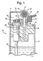
- Lighter 10 includes a housing 12 having a reservoir 14 for containing fuel and an upper frame 16 secured to the top of housing 12 and a windshield 17 mounted on the frame.
- Upper frame 16 includes a pair of upstanding arms 18 essentially located along the top of the lighter and between which is mounted an ignition mechanism, generally designated 20.
- the ignition mechanism 20 includes a device for generating a spark in a combustion ignition region 22. While many different types of spark-generation devices can be employed, preferably there is mounted between the arms 18 a spark wheel 24 which engages a flint 25 biased by spring 26 into engagement along the underside of the spark wheel 24.
- the spark wheel may comprise a conventional spark wheel having a roughened peripheral surface and flanked by a pair of drive wheels 27 fixed to the axle mounting the spark wheel whereby rotation of the spark wheel against flint 25 generates a spark which is directed into the ignition region 22.
- a valve 28 is provided for supplying fuel to the ignition region 22.
- the valve 28 includes a valve actuator stem 30 which, in a preferred form, is spring-biased into a valve-closed position by a spring, not shown, within the valve 28.
- Fuel is supplied from the fuel reservoir 14 via a tube 32 to the valve 28 such that when the valve stem 30 is raised against the bias of the spring, fuel is supplied to the ignition region 22.
- the foregoing-described ignition mechanism is conventional in nature and it will be appreciated that conventional spark-generating devices and valves can be used.
- an actuator for actuating the lighter and more particularly for moving the valve 28 between valve-closed and valve-open positions.
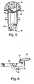
- the actuator includes a first element 40 having an end thereof terminating in a first finger-engageable surface 44.
- Central portions 41 of element 40 straddle the flint 25 and upstanding flint housing 42 ( Figure 1 ). The central portions 41 engage or bear against the legs of the second element 50.
- element 40 terminates in a catch 46 engageable with the valve stem 30 such that, upon pivoting element 40 by engaging a finger, e.g., a thumb, along the fnger-engageable surface 44 and depressing, e.g., pivoting, the element 40, the valve stem 30 may be raised, releasing fuel into the ignition region.
- the valve spring upon removal of finger pressure on the first finger-engageable surface 44, the valve spring displaces the valve stem 30 into the valve-closed position, returning the pivoted valve element 40 to its initial position.
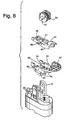
- the actuator also includes a second element 50 having at one end a second finger-engageable surface 52.
- the element 50 has a pair of legs 53 straddling the flint housing 42 and the central portions 41 of element 40. The legs terminate adjacent opposite ends thereof in a pair of laterally projecting cylindrical pins 54 which engage in the circular openings 43 in the arms 18 whereby the elements 40 and 50 are pivotally carried by the arms 18.
- the central portions 41 of element 40 are wedged between the legs 53 of element 50 and bear on flats 55 on element 50.
- Element 40 is retained in the lighter by the engagement of catch 46 and valve stem 30.
- Elements 40 and 50 are also pivotally mounted relative to one another.
- Element 50 also includes a spring which, in a preferred form, comprises a pair of leaf springs 56 having distal ends engageable against the upper frame 16, biasing the first and second elements 40 and 50, respectively, into a position where the finger-engageable surface 52 corresponds to the position of the conventional thumb press of a typical lighter in its non-actuated position.
- the springs 56 bias the element 50 such that its surface 52 and finger-engageable surface 44 of element 40, respectively, form a substantially continuous finger, e.g., thumb pad surface simulating a conventional thumb press of a typical lighter in a non-actuated position.
- first and second finger-engageable surfaces 44 and 52 may be shaped to engage one another when the surfaces lie in a continuous, for example, co-planar relation, forming essentially a single continuous compound thumb pad, thereby enabling the biased second element, when moved independently of the first element 40, to return under the bias of spring 56 to a position where the second surface 52 forms a continuation of the first surface 44.
- the surface 44 may be higher or lower relative to surface 52 in the non-actuated position of the lighter forming a discontinuous compound finger or thumb pad.
- the appearance of the surfaces of the elements 40 and 50 corresponds substantially to the appearance of a typical valve-actuating thumb pad of a conventional lighter. See, for example, Figures 2 and 5 .
- second finger-engageable surface 52 will cause the surface 52 to be depressed against the bias of springs 56 without depressing the surface 44 or pivoting lever 40 See Figure 3 .
- the surface 52 serves as a mock lever which can be depressed without effect, e.g., without assisting lighter actuation by moving the valve from a valve-closed to a valve-open position.
- the outer periphery of the surfaces 44 and 52 corresponds to a typical thumb pad, the existence of the discrete surface 44 is not readily noticeable, especially by a child. The child's efforts to depress the thumb pad will result substantially in depressing only the second surface 52 relative to the first surface 44 as illustrated in Figure 3 without effecting lighter ignition. While the surfaces 44 and 52 are illustrated as having different surface configurations, it will be appreciated that by providing similar, or identical surface configurations on both surfaces and providing them in the same color, the existence of the compound surfaces is essentially not noticeable which further inhibits actuation of the lighter by a child. Alternatively, contrasting colors, textures or other contrasting indicia may be employed on surfaces 44 and 52 to draw a child's attention away from surface 44 and toward surface 52.
- the second element 50 includes a pair of laterally extending pins 60 which are semi-cylindrical in configuration.
- the flat upper surface of the semi-cylindrical pins 60 extend in upwardly opening recesses in the legs 53 of the second element 50.
- the first element 40 of the actuator also has a pair of semi-cylindrical laterally extending pins 62 projecting from the central portions 41 thereof.
- the semi-cylindrical pins 60 and 62 in final assembly of the actuator have the flat sides thereof engaged with one another forming bifurcated cylindrical pins received in the openings 43 of arms 18.
Landscapes
- Engineering & Computer Science (AREA)
- Chemical & Material Sciences (AREA)
- Combustion & Propulsion (AREA)
- Mechanical Engineering (AREA)
- General Engineering & Computer Science (AREA)
- Lighters Containing Fuel (AREA)
- Socks And Pantyhose (AREA)
- Gloves (AREA)
- Cosmetics (AREA)
Claims (6)
- Sicherheitsfeuerzeug (10), umfassend:ein Feuerzeuggehäuse (12) mit einem Vorratsbehälter (14) zum Aufnehmen eines entflammbaren Brennstoffs;ein Ventil (28) zum Freigeben des Brennstoffs aus dem Vorratsbehälter (14) und beweglich zwischen Ventil-geöffnet- und Ventil-geschlossen-Positionen;eine Vorrichtung (20) zum Erzeugen eines Funkens zum Entzünden des aus dem Ventil (28) freigegebenen Brennstoffs, wenn das Ventil (28) in der Ventil-geöffnet-Position liegt; underste und zweite Elemente (40, 50), die für schwenkbare Bewegung an dem Feuerzeuggehäuse (12) montiert sind und jeweilige erste und zweite fingereingreifbare Oberflächen (44, 52) aufweisen, die in einer nicht betätigten Position zusammen eine im Wesentlichen kontinuierliche Daumenpolsteroberfläche bilden,das Sicherheitsfeuerzeug (10) dadurch gekennzeichnet, dassdas erste Element (40) an das Ventil (28) gekoppelt und durch Fingerdruck auf die erste Oberfläche (44) beweglich ist, um das Ventil (28) aus der Ventil-geschlossen-Position in die Ventil-geöffnet-Position zu bewegen,das zweite Element (50) durch Fingerdruck auf die zweite Oberfläche (52) zwischen einer ersten Position und einer zweiten, gedrückten Position beweglich ist, ohne das Ventil (28) aus der geschlossenen Position zu bewegen, wobei das erste Element (40) aus der Ventil-geschlossen-Position in die Ventil-geöffnet-Position selbst dann beweglich ist, wenn das zweite Element (50) in der zweiten, gedrückten Position ist,eine Feder (56), die das zweite Element (50) aus der zweiten, gedrückten Position zu der ersten Position vorspannt, unddie erste Oberfläche (44) von der zweiten Oberfläche (52) an allen Seiten umgeben oder begrenzt ist außer einer Seite zwischen der ersten Oberfläche (44) und der Funkenerzeugungsvorrichtung (20), so dass die erste Oberfläche (44) sich zwischen der zweiten Oberfläche (52) und der Funkenerzeugungsvorrichtung (20) befindet, um dadurch einen reduzierten Bereich zum Bewegen des ersten Elements (40), um das Ventil (28) zu betätigen, bereitstellt.
- Feuerzeug nach Anspruch 1, wobei die Oberflächen (44, 52) an einer Seite der Funkenerzeugungsvorrichtung (20) entfernt von dem Ventil (28) angeordnet sind.
- Feuerzeug nach Anspruch 1, wobei die erste und zweite fingereingreifbare Oberfläche (44, 52) zusammen ein zusammengesetztes fingereingreifbares Polster bilden.
- Feuerzeug nach Anspruch 1, wobei die Funkenerzeugungsvorrichtung (20) ein Funkenrad (24) und einen Feuerstein (25) enthält, die von dem Gehäuse (12) an einer Seite des Ventils (28) getragen werden, wobei die erste und zweite Oberfläche (44, 52) an einer Seite des Funkenrads (24) entfernt von dem Ventil (28) positioniert sind, wobei die erste Oberfläche (44) sich im Wesentlichen zwischen der zweiten Oberfläche (52) und dem Funkenrad (24) befindet.
- Feuerzeug nach Anspruch 1, wobei das erste und zweite Element (40, 50) relativ zueinander und unabhängig voneinander schwenkbar sind.
- Feuerzeug nach Anspruch 1, wobei die Feder (56) das zweite Element (50) für Bewegung derart vorspannt, dass die zweite Oberfläche (52) eine Fortsetzung der ersten Oberfläche (44) bildet, um damit ein zusammengesetztes Fingerpolster zu definieren, wenn das erste Element (40) in der Position liegt, die das Ventil (28) schließt.
Applications Claiming Priority (3)
| Application Number | Priority Date | Filing Date | Title |
|---|---|---|---|
| US09/477,336 US6224368B1 (en) | 2000-01-04 | 2000-01-04 | Safety lighter with compound finger pad |
| US477336 | 2000-01-04 | ||
| PCT/US2001/000124 WO2001050063A1 (en) | 2000-01-04 | 2001-01-03 | Safety lighter with compound finger pad |
Publications (3)
| Publication Number | Publication Date |
|---|---|
| EP1173709A1 EP1173709A1 (de) | 2002-01-23 |
| EP1173709A4 EP1173709A4 (de) | 2008-03-26 |
| EP1173709B1 true EP1173709B1 (de) | 2011-09-14 |
Family
ID=23895492
Family Applications (1)
| Application Number | Title | Priority Date | Filing Date |
|---|---|---|---|
| EP01900836A Expired - Lifetime EP1173709B1 (de) | 2000-01-04 | 2001-01-03 | Sicherheitsfeuerzeug mit zusammengesetztem presspolster |
Country Status (7)
| Country | Link |
|---|---|
| US (1) | US6224368B1 (de) |
| EP (1) | EP1173709B1 (de) |
| JP (1) | JP4287612B2 (de) |
| AT (1) | ATE524695T1 (de) |
| AU (1) | AU778465B2 (de) |
| CA (1) | CA2365219C (de) |
| WO (1) | WO2001050063A1 (de) |
Cited By (1)
| Publication number | Priority date | Publication date | Assignee | Title |
|---|---|---|---|---|
| EP4523552A4 (de) * | 2021-10-29 | 2026-04-22 | Long Chen | Rauchvorrichtung, zugehörige rauchentladungsvorrichtung und spezialfeuerzeug für die rauchvorrichtung |
Families Citing this family (14)
| Publication number | Priority date | Publication date | Assignee | Title |
|---|---|---|---|---|
| JP2001010360A (ja) * | 1999-06-28 | 2001-01-16 | Suzuki Motor Corp | ハイブリッド動力車両 |
| US6666678B2 (en) * | 1999-12-02 | 2003-12-23 | Calico Brands, Inc. | Multi-button piezoelectric child-resistant cigarette lighter |
| WO2002012817A1 (en) * | 2000-08-04 | 2002-02-14 | Showa Denko K.K. | Integrated heat exchanger |
| US6908302B2 (en) * | 2000-11-03 | 2005-06-21 | Bic Corporation | Multi-mode lighter |
| US6971870B2 (en) * | 2000-11-03 | 2005-12-06 | Bic Corporation | Multi-mode lighter |
| US7311518B2 (en) * | 2000-11-03 | 2007-12-25 | Bic Corporation | Multi-mode lighter |
| US7744368B2 (en) * | 2000-11-03 | 2010-06-29 | Bic Corporation | Multi-mode lighter |
| US6916171B2 (en) | 2000-11-03 | 2005-07-12 | Bic Corporation | Multi-mode lighter |
| US6488492B2 (en) | 2000-11-03 | 2002-12-03 | Bic Corporation | Multi-mode lighter |
| US6491515B1 (en) | 2000-11-03 | 2002-12-10 | Bic Corporation | Multi-mode lighter |
| US6726469B2 (en) * | 2000-11-03 | 2004-04-27 | Bic Corporation | Multi-mode lighter |
| US8653942B2 (en) | 2008-08-20 | 2014-02-18 | John Gibson Enterprises, Inc. | Portable biometric lighter |
| JP4942227B2 (ja) * | 2010-01-28 | 2012-05-30 | 株式会社サロメ | ガスライタ |
| US10502419B2 (en) | 2017-09-12 | 2019-12-10 | John Gibson Enterprises, Inc. | Portable biometric lighter |
Family Cites Families (6)
| Publication number | Priority date | Publication date | Assignee | Title |
|---|---|---|---|---|
| ES2015769A6 (es) * | 1989-08-04 | 1990-09-01 | Ind De Fosforos Y Encendedores | Dispositivo de seguridad para encendedores. |
| JPH0492142U (de) * | 1990-11-30 | 1992-08-11 | ||
| KR200202998Y1 (ko) * | 1998-03-11 | 2001-01-15 | 전종구 | 발화저지기능을 갖는 발화석 점화식 가스라이터 |
| US6022211A (en) * | 1998-04-20 | 2000-02-08 | Wang; Zhengge | Lighter |
| US5997282A (en) * | 1998-09-29 | 1999-12-07 | Man; Aman Chung Kai | Child-resistant piezo-electric safety lighter |
| US6095796A (en) * | 1999-12-02 | 2000-08-01 | Sung; Kil Yong | Double-button piezoelectric child-resistant cigarette lighter |
-
2000
- 2000-01-04 US US09/477,336 patent/US6224368B1/en not_active Expired - Lifetime
-
2001
- 2001-01-03 AT AT01900836T patent/ATE524695T1/de not_active IP Right Cessation
- 2001-01-03 WO PCT/US2001/000124 patent/WO2001050063A1/en not_active Ceased
- 2001-01-03 AU AU26253/01A patent/AU778465B2/en not_active Ceased
- 2001-01-03 EP EP01900836A patent/EP1173709B1/de not_active Expired - Lifetime
- 2001-01-03 CA CA2365219A patent/CA2365219C/en not_active Expired - Fee Related
- 2001-01-03 JP JP2001549965A patent/JP4287612B2/ja not_active Expired - Fee Related
Cited By (1)
| Publication number | Priority date | Publication date | Assignee | Title |
|---|---|---|---|---|
| EP4523552A4 (de) * | 2021-10-29 | 2026-04-22 | Long Chen | Rauchvorrichtung, zugehörige rauchentladungsvorrichtung und spezialfeuerzeug für die rauchvorrichtung |
Also Published As
| Publication number | Publication date |
|---|---|
| EP1173709A1 (de) | 2002-01-23 |
| US6224368B1 (en) | 2001-05-01 |
| CA2365219C (en) | 2010-06-22 |
| JP2003519350A (ja) | 2003-06-17 |
| ATE524695T1 (de) | 2011-09-15 |
| JP4287612B2 (ja) | 2009-07-01 |
| AU778465B2 (en) | 2004-12-09 |
| AU2625301A (en) | 2001-07-16 |
| EP1173709A4 (de) | 2008-03-26 |
| WO2001050063A1 (en) | 2001-07-12 |
| CA2365219A1 (en) | 2001-07-12 |
Similar Documents
| Publication | Publication Date | Title |
|---|---|---|
| EP1173709B1 (de) | Sicherheitsfeuerzeug mit zusammengesetztem presspolster | |
| AU686531B2 (en) | Lighter | |
| JP3027417B2 (ja) | 選択的に作動できるライター | |
| JPH05504826A (ja) | 二方向に選択的操作可能なライタ | |
| US5957680A (en) | Lighter having a guard member and cooperating blocking members | |
| EP0830546B1 (de) | Feuerzeug mit ringartige sicherung | |
| US5607295A (en) | Safety lock cigarette lighter | |
| US5788474A (en) | Safety lighter | |
| CA2114772A1 (en) | Lighter | |
| EP1214550B1 (de) | Sicherheitsfeuerzeug mit rotierenden radhauben | |
| EP0832395B1 (de) | Selektiv betätigbares feuerzeug | |
| US6926518B1 (en) | Safety lighter | |
| JP2009506291A (ja) | 子供に対して安全なロールプレス式ライター | |
| US20070009844A1 (en) | Safety device of a lighter | |
| US6860733B2 (en) | Safety gas lighter with a ratchet-pawl mechanism | |
| HK1009841B (en) | Lighter with looped guard | |
| HK1038054B (en) | Lighter having guard member and blocking members | |
| WO1990000704A1 (en) | Flame lighter | |
| GB2398623A (en) | Safety mechanism for a lighter | |
| MXPA97009378A (en) | Lighter with liner protector | |
| HK1011070B (en) | Selectively actuatable lighter |
Legal Events
| Date | Code | Title | Description |
|---|---|---|---|
| PUAI | Public reference made under article 153(3) epc to a published international application that has entered the european phase |
Free format text: ORIGINAL CODE: 0009012 |
|
| 17P | Request for examination filed |
Effective date: 20010929 |
|
| AK | Designated contracting states |
Kind code of ref document: A1 Designated state(s): AT BE CH CY DE DK ES FI FR GB GR IE IT LI LU MC NL PT SE TR |
|
| A4 | Supplementary search report drawn up and despatched |
Effective date: 20080227 |
|
| 17Q | First examination report despatched |
Effective date: 20080620 |
|
| GRAP | Despatch of communication of intention to grant a patent |
Free format text: ORIGINAL CODE: EPIDOSNIGR1 |
|
| GRAC | Information related to communication of intention to grant a patent modified |
Free format text: ORIGINAL CODE: EPIDOSCIGR1 |
|
| GRAS | Grant fee paid |
Free format text: ORIGINAL CODE: EPIDOSNIGR3 |
|
| GRAA | (expected) grant |
Free format text: ORIGINAL CODE: 0009210 |
|
| AK | Designated contracting states |
Kind code of ref document: B1 Designated state(s): AT BE CH CY DE DK ES FI FR GB GR IE IT LI LU MC NL PT SE TR |
|
| REG | Reference to a national code |
Ref country code: GB Ref legal event code: FG4D |
|
| REG | Reference to a national code |
Ref country code: CH Ref legal event code: EP |
|
| REG | Reference to a national code |
Ref country code: IE Ref legal event code: FG4D |
|
| REG | Reference to a national code |
Ref country code: DE Ref legal event code: R096 Ref document number: 60145294 Country of ref document: DE Effective date: 20111117 |
|
| REG | Reference to a national code |
Ref country code: NL Ref legal event code: VDEP Effective date: 20110914 |
|
| PG25 | Lapsed in a contracting state [announced via postgrant information from national office to epo] |
Ref country code: SE Free format text: LAPSE BECAUSE OF FAILURE TO SUBMIT A TRANSLATION OF THE DESCRIPTION OR TO PAY THE FEE WITHIN THE PRESCRIBED TIME-LIMIT Effective date: 20110914 Ref country code: FI Free format text: LAPSE BECAUSE OF FAILURE TO SUBMIT A TRANSLATION OF THE DESCRIPTION OR TO PAY THE FEE WITHIN THE PRESCRIBED TIME-LIMIT Effective date: 20110914 |
|
| PG25 | Lapsed in a contracting state [announced via postgrant information from national office to epo] |
Ref country code: AT Free format text: LAPSE BECAUSE OF FAILURE TO SUBMIT A TRANSLATION OF THE DESCRIPTION OR TO PAY THE FEE WITHIN THE PRESCRIBED TIME-LIMIT Effective date: 20110914 Ref country code: GR Free format text: LAPSE BECAUSE OF FAILURE TO SUBMIT A TRANSLATION OF THE DESCRIPTION OR TO PAY THE FEE WITHIN THE PRESCRIBED TIME-LIMIT Effective date: 20111215 Ref country code: CY Free format text: LAPSE BECAUSE OF FAILURE TO SUBMIT A TRANSLATION OF THE DESCRIPTION OR TO PAY THE FEE WITHIN THE PRESCRIBED TIME-LIMIT Effective date: 20110914 |
|
| REG | Reference to a national code |
Ref country code: AT Ref legal event code: MK05 Ref document number: 524695 Country of ref document: AT Kind code of ref document: T Effective date: 20110914 |
|
| PG25 | Lapsed in a contracting state [announced via postgrant information from national office to epo] |
Ref country code: BE Free format text: LAPSE BECAUSE OF FAILURE TO SUBMIT A TRANSLATION OF THE DESCRIPTION OR TO PAY THE FEE WITHIN THE PRESCRIBED TIME-LIMIT Effective date: 20110914 |
|
| PG25 | Lapsed in a contracting state [announced via postgrant information from national office to epo] |
Ref country code: NL Free format text: LAPSE BECAUSE OF FAILURE TO SUBMIT A TRANSLATION OF THE DESCRIPTION OR TO PAY THE FEE WITHIN THE PRESCRIBED TIME-LIMIT Effective date: 20110914 Ref country code: PT Free format text: LAPSE BECAUSE OF FAILURE TO SUBMIT A TRANSLATION OF THE DESCRIPTION OR TO PAY THE FEE WITHIN THE PRESCRIBED TIME-LIMIT Effective date: 20120116 Ref country code: IT Free format text: LAPSE BECAUSE OF FAILURE TO SUBMIT A TRANSLATION OF THE DESCRIPTION OR TO PAY THE FEE WITHIN THE PRESCRIBED TIME-LIMIT Effective date: 20110914 |
|
| PLBE | No opposition filed within time limit |
Free format text: ORIGINAL CODE: 0009261 |
|
| STAA | Information on the status of an ep patent application or granted ep patent |
Free format text: STATUS: NO OPPOSITION FILED WITHIN TIME LIMIT |
|
| PG25 | Lapsed in a contracting state [announced via postgrant information from national office to epo] |
Ref country code: DK Free format text: LAPSE BECAUSE OF FAILURE TO SUBMIT A TRANSLATION OF THE DESCRIPTION OR TO PAY THE FEE WITHIN THE PRESCRIBED TIME-LIMIT Effective date: 20110914 |
|
| REG | Reference to a national code |
Ref country code: DE Ref legal event code: R119 Ref document number: 60145294 Country of ref document: DE |
|
| 26N | No opposition filed |
Effective date: 20120615 |
|
| PG25 | Lapsed in a contracting state [announced via postgrant information from national office to epo] |
Ref country code: MC Free format text: LAPSE BECAUSE OF NON-PAYMENT OF DUE FEES Effective date: 20120131 |
|
| REG | Reference to a national code |
Ref country code: CH Ref legal event code: PL |
|
| GBPC | Gb: european patent ceased through non-payment of renewal fee |
Effective date: 20120103 |
|
| REG | Reference to a national code |
Ref country code: DE Ref legal event code: R097 Ref document number: 60145294 Country of ref document: DE Effective date: 20120615 |
|
| REG | Reference to a national code |
Ref country code: FR Ref legal event code: ST Effective date: 20120928 |
|
| REG | Reference to a national code |
Ref country code: IE Ref legal event code: MM4A |
|
| PG25 | Lapsed in a contracting state [announced via postgrant information from national office to epo] |
Ref country code: LI Free format text: LAPSE BECAUSE OF NON-PAYMENT OF DUE FEES Effective date: 20120131 Ref country code: GB Free format text: LAPSE BECAUSE OF NON-PAYMENT OF DUE FEES Effective date: 20120103 Ref country code: DE Free format text: LAPSE BECAUSE OF NON-PAYMENT OF DUE FEES Effective date: 20120801 Ref country code: CH Free format text: LAPSE BECAUSE OF NON-PAYMENT OF DUE FEES Effective date: 20120131 |
|
| REG | Reference to a national code |
Ref country code: DE Ref legal event code: R119 Ref document number: 60145294 Country of ref document: DE Effective date: 20120801 |
|
| PG25 | Lapsed in a contracting state [announced via postgrant information from national office to epo] |
Ref country code: FR Free format text: LAPSE BECAUSE OF NON-PAYMENT OF DUE FEES Effective date: 20120131 |
|
| PG25 | Lapsed in a contracting state [announced via postgrant information from national office to epo] |
Ref country code: IE Free format text: LAPSE BECAUSE OF NON-PAYMENT OF DUE FEES Effective date: 20120103 |
|
| PG25 | Lapsed in a contracting state [announced via postgrant information from national office to epo] |
Ref country code: ES Free format text: LAPSE BECAUSE OF FAILURE TO SUBMIT A TRANSLATION OF THE DESCRIPTION OR TO PAY THE FEE WITHIN THE PRESCRIBED TIME-LIMIT Effective date: 20111225 |
|
| PG25 | Lapsed in a contracting state [announced via postgrant information from national office to epo] |
Ref country code: TR Free format text: LAPSE BECAUSE OF FAILURE TO SUBMIT A TRANSLATION OF THE DESCRIPTION OR TO PAY THE FEE WITHIN THE PRESCRIBED TIME-LIMIT Effective date: 20110914 |
|
| PG25 | Lapsed in a contracting state [announced via postgrant information from national office to epo] |
Ref country code: LU Free format text: LAPSE BECAUSE OF NON-PAYMENT OF DUE FEES Effective date: 20120103 |