EP1172650A2 - Capteur de gaz toxiques combiné avec un capteur d'oxygène - Google Patents
Capteur de gaz toxiques combiné avec un capteur d'oxygène Download PDFInfo
- Publication number
- EP1172650A2 EP1172650A2 EP01305992A EP01305992A EP1172650A2 EP 1172650 A2 EP1172650 A2 EP 1172650A2 EP 01305992 A EP01305992 A EP 01305992A EP 01305992 A EP01305992 A EP 01305992A EP 1172650 A2 EP1172650 A2 EP 1172650A2
- Authority
- EP
- European Patent Office
- Prior art keywords
- sensor
- toxic gas
- oxygen
- oxygen sensor
- diffusion barrier
- Prior art date
- Legal status (The legal status is an assumption and is not a legal conclusion. Google has not performed a legal analysis and makes no representation as to the accuracy of the status listed.)
- Granted
Links
Images
Classifications
-
- G—PHYSICS
- G01—MEASURING; TESTING
- G01N—INVESTIGATING OR ANALYSING MATERIALS BY DETERMINING THEIR CHEMICAL OR PHYSICAL PROPERTIES
- G01N27/00—Investigating or analysing materials by the use of electric, electrochemical, or magnetic means
- G01N27/26—Investigating or analysing materials by the use of electric, electrochemical, or magnetic means by investigating electrochemical variables; by using electrolysis or electrophoresis
- G01N27/403—Cells and electrode assemblies
- G01N27/404—Cells with anode, cathode and cell electrolyte on the same side of a permeable membrane which separates them from the sample fluid, e.g. Clark-type oxygen sensors
-
- G—PHYSICS
- G01—MEASURING; TESTING
- G01N—INVESTIGATING OR ANALYSING MATERIALS BY DETERMINING THEIR CHEMICAL OR PHYSICAL PROPERTIES
- G01N33/00—Investigating or analysing materials by specific methods not covered by groups G01N1/00 - G01N31/00
- G01N33/0004—Gaseous mixtures, e.g. polluted air
- G01N33/0009—General constructional details of gas analysers, e.g. portable test equipment
- G01N33/007—Arrangements to check the analyser
Definitions
- This invention concerns improvements in or relating to electrochemical, amperometric gas sensors, for example toxic gas sensors or oxygen sensors of the kind disclosed in UK Patents Nos 1 571 282, 2 094 055.
- An object of the present invention is thus to provide an improved sensor for detecting both toxic gas and oxygen levels which obviates the disadvantage attaching to conventional sensors.
- the oxygen sensor is mounted such that its diffusion barrier communicates with the downstream side of the diffusion barrier of the toxic gas sensor.
- the diffusion barriers are of the capillary hole type as a preference, but it is to be understood that other types of barrier, for example solid membrane barriers or Knudsen barriers, may be employed. It is to be understood that the diffusion barrier of one of the sensors may be different from that of the other sensor.
- the oxygen sensor is so placed as to monitor the oxygen concentration within the region between the toxic gas sensor diffusion barrier and its sensing electrode.
- the toxic gas diffusion barrier will normally present no significant restriction to the ingress of oxygen from the ambient air and the oxygen sensor can function in its normal way to detect oxygen deficiency in the ambient air.
- the oxygen sensor In the event that the toxic sensor diffusion barrier becomes blocked, the oxygen sensor will consume any oxygen within the internal space of the toxic sensor. As a result the oxygen sensor signal will decline and eventually an oxygen deficiency alarm will be initiated.
- a second oxygen sensor In order to differentiate unambiguously between a blocked diffusion barrier on the toxic gas sensor and a genuine oxygen deficiency condition in the ambient environment, a second oxygen sensor with its capillary diffusion barrier open directly to the external environment may be provided. However, in the absence of a second oxygen sensor, a fail-safe alarm will be given in the event of either a low oxygen condition or a blocked diffusion on the toxic gas sensor.
- Any suitable means may be provided for securing the sensors together to form a modular unit.
- a conventional toxic gas sensor such for example as is disclosed in UK Patent No 2 094 005
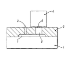
- a body 1 which has a top plate 2, shown in section, secured to its relatively upper face.
- the manner of securement of the plate 2 to the sensor body 1 is not shown in the drawing but may be selected from any of the conventional means known in the art, such as bolting, crimping using outer metal envelopes, ultrasonic welding, or 'snapfits' or any other suitable means.
- the top plate 2 has a controlling diffusion barrier 3 which determines the sensitivity response of the sensor to the toxic gas as described for example in UK Patent No 1 572 282.
- the diffusion barrier communicates from the ambient air, through the top plate 2 into a cavity 7 which may optionally be filled with a porous chemical filter material for removing cross interfering gases as described in US Patent No 4 633 704.
- the toxic gas to be sensed diffuses through the cavity and any filter material present with no significant diffusion resistance, compared to the diffusion barrier 3, to the sensing electrode located in the sensor body 1 where it reacts to generate a signal current proportional to the gas concentration.
- the sensing electrode located in the sensor body 1 where it reacts to generate a signal current proportional to the gas concentration.
- the usual and requisite components for the toxic gas sensor as described for example in UK Patent No 2 094 005, namely counter electrode, reference electrode (optional), separators, electrolyte and other elements which the skilled addressee will recognise as being necessary for the operation of the sensor.
- the sensor may optionally incorporate additional, auxiliary electrodes as described for example in EP 0126623.
- the top plate 2 has an oxygen sensor 4 mounted on its outer surface.
- the sensor 4 has an inlet 6 communicating through a relatively large aperture 5 into the cavity 7.
- the sensor 4 may be a conventional amperometric, diffusion-controlled type known to those skilled in the art and as described for example in UK Patent No 1 571 282.
- the inlet 6 is a controlling diffusion barrier of the oxygen sensor 4 and is a capillary hole, but other types of controlling diffusion barrier may in the alternative be employed in the invention, for example solid membranes of Knudsen barriers.
- the method of attachment of oxygen sensor 4 to the top plate 2 is not shown but can be of any suitable design that can achieve a gas tight seal between the oxygen sensor 4 and the top plate. It is important that the oxygen supply pathway to the sensor 4 is predominantly, if not exclusively, through the toxic gas sensor diffusion 3 and the cavity 7. The cavity 7, with any filter material present, and the aperture 5 should present only minimal diffusion resistance to oxygen accessing the oxygen sensor compared to the oxygen sensor controlling barrier 6 and the toxic sensor diffusion barrier 3.
- the instruments of fixed detection installations incorporating such sensors as described herein are first subjected to a calibration and check routine with test gases.
- the functioning of the toxic gas sensor, including its diffusion barrier 3 would be tested and calibrated by exposing the sensor to a test gas containing a known concentration of the toxic gas to be measured when in service.
- the oxygen sensor test and calibration would be conducted in clean air.
- the toxic gas sensor and the oxygen sensor could be tested and calibrated simultaneously using a test gas composed of toxic gas and oxygen at known concentrations with a suitable balance gas such as nitrogen.
- this test gas could comprise a known concentration of toxic gas in clean air.
- Some toxic gases such as nitric oxide cannot be stored in pressurised gas cylinders in the presence of oxygen due to chemical reaction with the oxygen. In the case of nitric oxide for example, the nitric oxide reacts with oxygen becoming converted to nitrogen dioxide. In such cases the testing and calibration would need to be carried out with separate anaerobic mixtures of the toxic gas and clean air.
- Another test that could be conducted during the calibration and check routine would be to measure the oxygen sensor output with a simple block on the toxic gas sensor controlling diffusion barrier 3 to confirm that any oxygen leaks to the oxygen sensor 4 are insignificant, relative to the diffusion pathway through the toxic gas sensor diffusion barrier, and also to confirm the level to which the output from the oxygen sensor 4 would reduce in the event of a full blockage of the toxic sensor diffusion barrier inlet.
- the calibrated and checked sensor would provide an oxygen measurement from the oxygen sensor 4 given by the reciprocal relationship set forth supra .
- the instrument output would have been set during the calibration routine to read 20.9% oxygen in air.
- the oxygen sensor 4 would reduce accordingly and the instrument would produce an alarm.
- the oxygen sensor 4 would reduce and an alarm produced in the event of a reduced oxygen concentration level in the external ambient, even though the controlling diffusion hole 3 were not blocked.
- a second oxygen sensor may be employed to monitor external ambient oxygen levels. Where two oxygen sensors are provided, to avoid the pair running continuously, the second external sensor could be switched off and only activated if the internal sensor indicated a reduced oxygen concentration. In this way the instrument would be able to differentiate between a blocked toxic sensor diffusion barrier and genuine oxygen deficiency condition in the external ambient.
Landscapes
- Chemical & Material Sciences (AREA)
- Life Sciences & Earth Sciences (AREA)
- Health & Medical Sciences (AREA)
- Biochemistry (AREA)
- Chemical Kinetics & Catalysis (AREA)
- Electrochemistry (AREA)
- Physics & Mathematics (AREA)
- Analytical Chemistry (AREA)
- Molecular Biology (AREA)
- General Health & Medical Sciences (AREA)
- General Physics & Mathematics (AREA)
- Immunology (AREA)
- Pathology (AREA)
- Investigating Or Analyzing Materials By The Use Of Fluid Adsorption Or Reactions (AREA)
- Sampling And Sample Adjustment (AREA)
- Measuring Oxygen Concentration In Cells (AREA)
Applications Claiming Priority (2)
| Application Number | Priority Date | Filing Date | Title |
|---|---|---|---|
| GB0017246 | 2000-07-14 | ||
| GB0017246A GB2364779A (en) | 2000-07-14 | 2000-07-14 | Toxic gas sensor with monitoring of diffusion barrier |
Related Child Applications (1)
| Application Number | Title | Priority Date | Filing Date |
|---|---|---|---|
| EP09176002.5 Division-Into | 2009-11-13 |
Publications (3)
| Publication Number | Publication Date |
|---|---|
| EP1172650A2 true EP1172650A2 (fr) | 2002-01-16 |
| EP1172650A3 EP1172650A3 (fr) | 2003-01-22 |
| EP1172650B1 EP1172650B1 (fr) | 2010-08-25 |
Family
ID=9895621
Family Applications (1)
| Application Number | Title | Priority Date | Filing Date |
|---|---|---|---|
| EP01305992A Expired - Lifetime EP1172650B1 (fr) | 2000-07-14 | 2001-07-11 | Instrument comprenant un capteur de gaz toxique combiné à sûreté intégrée. |
Country Status (5)
| Country | Link |
|---|---|
| US (1) | US6562208B2 (fr) |
| EP (1) | EP1172650B1 (fr) |
| CA (1) | CA2353033C (fr) |
| DE (1) | DE60142870D1 (fr) |
| GB (1) | GB2364779A (fr) |
Families Citing this family (20)
| Publication number | Priority date | Publication date | Assignee | Title |
|---|---|---|---|---|
| EP2234394A1 (fr) * | 2001-10-11 | 2010-09-29 | Mosaid Technologies Incorporated | Dispositif de couplage |
| US10598410B2 (en) * | 2009-05-12 | 2020-03-24 | Reflect Scientific Inc. | Self-powered, long-term, low-temperature, controlled shipping unit |
| US9689833B2 (en) | 2011-10-11 | 2017-06-27 | Life Safety Distribution Ag | Auxiliary micro-electrodes for diagnostics of electrochemical gas sensors |
| US9377435B2 (en) | 2011-10-11 | 2016-06-28 | Honeywell International Inc. | Auxiliary gas diffusion electrodes for diagnostics of electrochemical gas sensors |
| US9784755B2 (en) | 2011-10-14 | 2017-10-10 | Msa Technology, Llc | Sensor interrogation |
| US9528957B2 (en) * | 2011-10-14 | 2016-12-27 | Msa Technology, Llc | Sensor interrogation |
| US10908111B2 (en) | 2011-10-14 | 2021-02-02 | Msa Technology, Llc | Sensor interrogation |
| US9562873B2 (en) * | 2011-10-14 | 2017-02-07 | Msa Technology, Llc | Sensor interrogation |
| CN102914575A (zh) * | 2012-08-14 | 2013-02-06 | 尚沃医疗电子无锡有限公司 | 气体传感器 |
| EP2972277B1 (fr) * | 2013-03-12 | 2022-11-23 | MSA Technology, LLC | Interrogation de capteur de gaz |
| US11112378B2 (en) | 2019-06-11 | 2021-09-07 | Msa Technology, Llc | Interrogation of capillary-limited sensors |
| CN110261458A (zh) * | 2019-07-29 | 2019-09-20 | 盛密科技(上海)有限公司 | 一种电化学气体传感器 |
| TWM596345U (zh) * | 2020-03-05 | 2020-06-01 | 晶元光電股份有限公司 | 氣體感測器的量測設備 |
| US11828210B2 (en) | 2020-08-20 | 2023-11-28 | Denso International America, Inc. | Diagnostic systems and methods of vehicles using olfaction |
| US11813926B2 (en) | 2020-08-20 | 2023-11-14 | Denso International America, Inc. | Binding agent and olfaction sensor |
| US11881093B2 (en) | 2020-08-20 | 2024-01-23 | Denso International America, Inc. | Systems and methods for identifying smoking in vehicles |
| US11760169B2 (en) | 2020-08-20 | 2023-09-19 | Denso International America, Inc. | Particulate control systems and methods for olfaction sensors |
| US11760170B2 (en) | 2020-08-20 | 2023-09-19 | Denso International America, Inc. | Olfaction sensor preservation systems and methods |
| US11932080B2 (en) | 2020-08-20 | 2024-03-19 | Denso International America, Inc. | Diagnostic and recirculation control systems and methods |
| US11636870B2 (en) | 2020-08-20 | 2023-04-25 | Denso International America, Inc. | Smoking cessation systems and methods |
Citations (1)
| Publication number | Priority date | Publication date | Assignee | Title |
|---|---|---|---|---|
| GB2288873A (en) | 1994-04-28 | 1995-11-01 | Univ Middlesex Serv Ltd | Multi-component gas analysis apparatus |
Family Cites Families (11)
| Publication number | Priority date | Publication date | Assignee | Title |
|---|---|---|---|---|
| USRE31914E (en) * | 1970-11-10 | 1985-06-18 | Becton Dickinson & Company | Electrochemical gas detection method |
| GB1571282A (en) * | 1976-03-11 | 1980-07-09 | City Tech | Gas sensor |
| DE2638241C2 (de) | 1976-08-25 | 1982-08-19 | SMS Schloemann-Siemag AG, 4000 Düsseldorf | Anordnung eines Walzenzapfenlagers in einem Einbaustück eines Walzgerüstes |
| GB2094005B (en) * | 1981-02-03 | 1985-05-30 | Coal Industry Patents Ltd | Electrochemical gas sensor |
| EP0095277A3 (fr) | 1982-05-26 | 1984-07-04 | City Technology Limited | Capteur de gaz |
| JPS6276176A (ja) | 1985-09-20 | 1987-04-08 | モレツクス インコ−ポレ−テツド | 電気コネクタ組立体 |
| US5273640A (en) * | 1990-06-11 | 1993-12-28 | Matsushita Electric Works, Ltd. | Electrochemical gas sensor |
| EP0472829A3 (en) * | 1990-08-31 | 1993-01-07 | International Business Machines Corporation | Multicomputer complex and distributed shared data memory |
| DE4230602C2 (de) * | 1992-09-12 | 1995-04-20 | Draegerwerk Ag | Elektrochemischer Sensor mit modularem Aufbau |
| DE19533911C1 (de) * | 1995-09-13 | 1996-05-09 | Draegerwerk Ag | Elektrochemische Meßzelle |
| DE19622931C2 (de) * | 1996-06-07 | 2001-02-22 | Draegerwerk Ag | Elektrochemischer Mehrgassensor |
-
2000
- 2000-07-14 GB GB0017246A patent/GB2364779A/en not_active Withdrawn
-
2001
- 2001-07-11 DE DE60142870T patent/DE60142870D1/de not_active Expired - Lifetime
- 2001-07-11 EP EP01305992A patent/EP1172650B1/fr not_active Expired - Lifetime
- 2001-07-12 US US09/902,650 patent/US6562208B2/en not_active Expired - Lifetime
- 2001-07-12 CA CA002353033A patent/CA2353033C/fr not_active Expired - Fee Related
Patent Citations (1)
| Publication number | Priority date | Publication date | Assignee | Title |
|---|---|---|---|---|
| GB2288873A (en) | 1994-04-28 | 1995-11-01 | Univ Middlesex Serv Ltd | Multi-component gas analysis apparatus |
Also Published As
| Publication number | Publication date |
|---|---|
| DE60142870D1 (de) | 2010-10-07 |
| EP1172650A3 (fr) | 2003-01-22 |
| CA2353033C (fr) | 2006-05-16 |
| US6562208B2 (en) | 2003-05-13 |
| CA2353033A1 (fr) | 2002-01-14 |
| EP1172650B1 (fr) | 2010-08-25 |
| GB0017246D0 (en) | 2000-08-30 |
| GB2364779A (en) | 2002-02-06 |
| US20020036137A1 (en) | 2002-03-28 |
Similar Documents
| Publication | Publication Date | Title |
|---|---|---|
| CA2353033C (fr) | Ameliorations dans les detecteurs de gaz ou ayant trait a ceux-ci | |
| US5667653A (en) | Electrochemical sensor | |
| US5932079A (en) | Electrochemical multigas sensor | |
| TW376449B (en) | Gas sensors | |
| US8414751B2 (en) | Gas sensor with test gas generator | |
| US20070158210A1 (en) | Gas-monitoring assembly comprising one or more gas sensors and one or more getters, and method of using same | |
| EP0084935B1 (fr) | Dispositif de détection de gaz | |
| US20010045119A1 (en) | Method and apparatus for determining concentration of a gas | |
| AU2003209004A1 (en) | Self-calibrating carbon monoxide detector and method | |
| US5733436A (en) | Method for determining the state of an electrochemical gas sensor | |
| US8916037B1 (en) | Instrument and method for measuring high concentrations of carbon monoxide in a gaseous sample | |
| KR980003576A (ko) | 질소산화물 센서 | |
| JP2008261857A (ja) | ゼロ較正機能を備えた電気化学センサおよび較正方法 | |
| US7645367B2 (en) | Gas-measuring system with gas sensor and gas generator | |
| CA2641889C (fr) | Supervision de detecteurs electrochimiques de monoxyde de carbone | |
| GB2202053A (en) | Apparatus for measuring combustible gas concentration in flue gas | |
| GB2305247A (en) | Electrochemical measuring cell for detecting several gases | |
| US6635160B1 (en) | Gas sensor | |
| WO2007115801A1 (fr) | Capteur d'oxygène | |
| US5635627A (en) | Carbon monoxide sensor having mercury doped electrodes | |
| CN1152860A (zh) | 血内气体探针 | |
| US11112378B2 (en) | Interrogation of capillary-limited sensors | |
| US4963324A (en) | Colorimetric dosimeter | |
| EP0331696A1 (fr) | Technique de reduction du bruit pour cellules electrochimiques | |
| WO2001031326A1 (fr) | Ensemble capteur de gaz electrochimique et procede |
Legal Events
| Date | Code | Title | Description |
|---|---|---|---|
| PUAI | Public reference made under article 153(3) epc to a published international application that has entered the european phase |
Free format text: ORIGINAL CODE: 0009012 |
|
| AK | Designated contracting states |
Kind code of ref document: A2 Designated state(s): AT BE CH CY DE DK ES FI FR GB GR IE IT LI LU MC NL PT SE TR |
|
| AX | Request for extension of the european patent |
Free format text: AL;LT;LV;MK;RO;SI |
|
| PUAL | Search report despatched |
Free format text: ORIGINAL CODE: 0009013 |
|
| AK | Designated contracting states |
Kind code of ref document: A3 Designated state(s): AT BE CH CY DE DK ES FI FR GB GR IE IT LI LU MC NL PT SE TR |
|
| AX | Request for extension of the european patent |
Free format text: AL;LT;LV;MK;RO;SI |
|
| 17P | Request for examination filed |
Effective date: 20030721 |
|
| AKX | Designation fees paid |
Designated state(s): DE FR GB IT |
|
| 17Q | First examination report despatched |
Effective date: 20070308 |
|
| GRAP | Despatch of communication of intention to grant a patent |
Free format text: ORIGINAL CODE: EPIDOSNIGR1 |
|
| RTI1 | Title (correction) |
Free format text: AN INSTRUMENT COMPRISING A FAIL-SAFE COMBINED TOXIC GAS SENSOR. |
|
| GRAS | Grant fee paid |
Free format text: ORIGINAL CODE: EPIDOSNIGR3 |
|
| GRAA | (expected) grant |
Free format text: ORIGINAL CODE: 0009210 |
|
| AK | Designated contracting states |
Kind code of ref document: B1 Designated state(s): DE FR GB IT |
|
| REG | Reference to a national code |
Ref country code: GB Ref legal event code: FG4D |
|
| REF | Corresponds to: |
Ref document number: 60142870 Country of ref document: DE Date of ref document: 20101007 Kind code of ref document: P |
|
| PG25 | Lapsed in a contracting state [announced via postgrant information from national office to epo] |
Ref country code: IT Free format text: LAPSE BECAUSE OF FAILURE TO SUBMIT A TRANSLATION OF THE DESCRIPTION OR TO PAY THE FEE WITHIN THE PRESCRIBED TIME-LIMIT Effective date: 20100825 |
|
| PLBE | No opposition filed within time limit |
Free format text: ORIGINAL CODE: 0009261 |
|
| STAA | Information on the status of an ep patent application or granted ep patent |
Free format text: STATUS: NO OPPOSITION FILED WITHIN TIME LIMIT |
|
| 26N | No opposition filed |
Effective date: 20110526 |
|
| PGFP | Annual fee paid to national office [announced via postgrant information from national office to epo] |
Ref country code: GB Payment date: 20110622 Year of fee payment: 11 |
|
| REG | Reference to a national code |
Ref country code: DE Ref legal event code: R097 Ref document number: 60142870 Country of ref document: DE Effective date: 20110526 |
|
| PGFP | Annual fee paid to national office [announced via postgrant information from national office to epo] |
Ref country code: FR Payment date: 20110727 Year of fee payment: 11 |
|
| PGFP | Annual fee paid to national office [announced via postgrant information from national office to epo] |
Ref country code: DE Payment date: 20110729 Year of fee payment: 11 |
|
| GBPC | Gb: european patent ceased through non-payment of renewal fee |
Effective date: 20120711 |
|
| REG | Reference to a national code |
Ref country code: FR Ref legal event code: ST Effective date: 20130329 |
|
| PG25 | Lapsed in a contracting state [announced via postgrant information from national office to epo] |
Ref country code: DE Free format text: LAPSE BECAUSE OF NON-PAYMENT OF DUE FEES Effective date: 20130201 Ref country code: FR Free format text: LAPSE BECAUSE OF NON-PAYMENT OF DUE FEES Effective date: 20120731 Ref country code: GB Free format text: LAPSE BECAUSE OF NON-PAYMENT OF DUE FEES Effective date: 20120711 |
|
| REG | Reference to a national code |
Ref country code: DE Ref legal event code: R119 Ref document number: 60142870 Country of ref document: DE Effective date: 20130201 |