EP1172517A1 - Volet roulant comportant des moyens de blocage de l'arbre d'enroulement de son tablier. - Google Patents
Volet roulant comportant des moyens de blocage de l'arbre d'enroulement de son tablier. Download PDFInfo
- Publication number
- EP1172517A1 EP1172517A1 EP01440210A EP01440210A EP1172517A1 EP 1172517 A1 EP1172517 A1 EP 1172517A1 EP 01440210 A EP01440210 A EP 01440210A EP 01440210 A EP01440210 A EP 01440210A EP 1172517 A1 EP1172517 A1 EP 1172517A1
- Authority
- EP
- European Patent Office
- Prior art keywords
- winding shaft
- roller shutter
- blade
- latch
- hand
- Prior art date
- Legal status (The legal status is an assumption and is not a legal conclusion. Google has not performed a legal analysis and makes no representation as to the accuracy of the status listed.)
- Granted
Links
- 238000004804 winding Methods 0.000 title claims description 151
- 230000000903 blocking effect Effects 0.000 title claims description 53
- 230000002441 reversible effect Effects 0.000 claims description 15
- 230000009471 action Effects 0.000 claims description 11
- 239000002184 metal Substances 0.000 claims description 4
- 238000005096 rolling process Methods 0.000 description 11
- 238000005304 joining Methods 0.000 description 4
- 230000001846 repelling effect Effects 0.000 description 4
- 230000008901 benefit Effects 0.000 description 3
- 238000013461 design Methods 0.000 description 3
- 238000010586 diagram Methods 0.000 description 3
- 238000000034 method Methods 0.000 description 3
- 238000012549 training Methods 0.000 description 3
- 238000006677 Appel reaction Methods 0.000 description 2
- 238000006073 displacement reaction Methods 0.000 description 2
- 210000000003 hoof Anatomy 0.000 description 2
- 238000004519 manufacturing process Methods 0.000 description 2
- 230000008569 process Effects 0.000 description 2
- 230000015556 catabolic process Effects 0.000 description 1
- 238000005520 cutting process Methods 0.000 description 1
- 238000006731 degradation reaction Methods 0.000 description 1
- 238000011161 development Methods 0.000 description 1
- 230000006870 function Effects 0.000 description 1
- 238000005259 measurement Methods 0.000 description 1
- 210000000056 organ Anatomy 0.000 description 1
- 230000007306 turnover Effects 0.000 description 1
- 239000002699 waste material Substances 0.000 description 1
Images

Classifications
-
- E—FIXED CONSTRUCTIONS
- E06—DOORS, WINDOWS, SHUTTERS, OR ROLLER BLINDS IN GENERAL; LADDERS
- E06B—FIXED OR MOVABLE CLOSURES FOR OPENINGS IN BUILDINGS, VEHICLES, FENCES OR LIKE ENCLOSURES IN GENERAL, e.g. DOORS, WINDOWS, BLINDS, GATES
- E06B9/00—Screening or protective devices for wall or similar openings, with or without operating or securing mechanisms; Closures of similar construction
- E06B9/56—Operating, guiding or securing devices or arrangements for roll-type closures; Spring drums; Tape drums; Counterweighting arrangements therefor
- E06B9/80—Safety measures against dropping or unauthorised opening; Braking or immobilising devices; Devices for limiting unrolling
- E06B9/82—Safety measures against dropping or unauthorised opening; Braking or immobilising devices; Devices for limiting unrolling automatic
- E06B9/88—Safety measures against dropping or unauthorised opening; Braking or immobilising devices; Devices for limiting unrolling automatic for limiting unrolling
-
- E—FIXED CONSTRUCTIONS
- E06—DOORS, WINDOWS, SHUTTERS, OR ROLLER BLINDS IN GENERAL; LADDERS
- E06B—FIXED OR MOVABLE CLOSURES FOR OPENINGS IN BUILDINGS, VEHICLES, FENCES OR LIKE ENCLOSURES IN GENERAL, e.g. DOORS, WINDOWS, BLINDS, GATES
- E06B9/00—Screening or protective devices for wall or similar openings, with or without operating or securing mechanisms; Closures of similar construction
- E06B9/56—Operating, guiding or securing devices or arrangements for roll-type closures; Spring drums; Tape drums; Counterweighting arrangements therefor
- E06B9/68—Operating devices or mechanisms, e.g. with electric drive
- E06B2009/6809—Control
- E06B2009/6872—Control using counters to determine shutter position
- E06B2009/6881—Mechanical counters
Definitions
- the present invention relates to a rolling shutter comprising a winding shaft on which is wound and from which an apron takes place, defined by a succession of blades, and connected, directly or through a connection, to said winding shaft, the latter being of a hand, kept in rotation at its ends by bearings support comprising a rotor and a stator and, on the other hand, operated via a drive device, said component being supplemented by means capable of ensuring the locking in rotation of said winding shaft in the direction of unfolding and at the end of the deck's deployment stroke, such blocking means being designed capable, on the one hand, of being kept in an inactive position and on the other hand and at on the contrary, to adopt an active position for blocking said shaft winding under the impulse of a control member.
- This invention relates to the field of shutter manufacturing roller shutters, especially those intended to equip the door, the window or other of a building.
- rollers comprising a winding shaft on which is wound and from which takes place an apron defined by a succession of blades, driven by a device appropriate training which, depending on the case, may be of the type electric or manual.
- Such a drive device is designed capable of allowing, on the one hand, the winding of said deck, in particular inside of a box.
- said rolling shutter usually receives means capable of blocking rotation and / or to prevent the rotational drive of said shaft winding, this at the end of the winding stroke of said apron.
- Such means make it possible, in particular, to avoid cause damage to the resulting apron, by example, of an inappropriate traction on the latter.
- such means can be defined by means of the type mechanical or electrical, in particular implementing a measurement of the engine load.
- This drive device is designed capable of allowing, other share, the course of said apron.
- roller shutters of the state of the art comprising a winding shaft actuated by a manual type drive device, it is generally not provided with means capable of blocking in rotation of said winding shaft, this at the end of travel deployment of said deck.
- said roller shutter can be fitted with a locking device automatic shutter at the end of the deployment stroke of this latest.
- the motorization system is then designed capable, on the one hand, to detect, at the end of deployment of said deployment apron, a variation and / or an increase in the load of the motor due to blockage of the bulkhead and, on the other hand, to be cut the supply of said motor.
- this locking device is designed capable of exerting pressure on said apron so that it is in no way compatible with an apron constituted by a succession of flexible and / or deformable blades.
- Roller shutters are also known comprising a deck, connected to the winding shaft via a strap or the like, but devoid of any device for locking.
- a deck connected to the winding shaft via a strap or the like, but devoid of any device for locking.
- Such an embodiment in no way allows detect a variation in engine load, the latter being then susceptible, after full deployment of said deck, ensure the winding of the latter in the opposite direction with the disadvantages mentioned above.
- roller shutter comprising an apron, defined by a succession of blades, and wound on a cylinder made up of two blades curved fixed on the cylindrical surface of two barrels rotatably mounted on a fixed shaft.
- This roller shutter includes a device for limiting the unwinding of the apron consisting, on the one hand, of a socket threaded on said fixed shaft, made integral with the latter, and provided with stops and, on the other hand, by a finger locking.
- the latter is pivotally mounted on an axis, on the one hand, offset from the cylinder axis winding and, on the other hand, supported by two flanges rotatably mounted on said fixed shaft and integral with the blades shapely.
- Said locking finger is urged to pivot in direction of the stops that said socket comprises, this in position limiting the flow of the deck.
- the present invention is intended to overcome the disadvantages of the state of the art roller shutters.
- said invention relates to a rolling shutter comprising a winding shaft on which it is wound and from which an apron takes place, defined by a succession blades, and connected, directly or through a connecting member, to said winding shaft, the latter being, on the one hand, kept rotating at its ends by support bearings comprising a rotor and a stator and, on the other hand, operated through a device drive, said component being supplemented by suitable means to ensure the locking in rotation of said winding shaft in the direction of the unfolding and at the end of the deployment course of the apron, such blocking means being designed capable, of a on the one hand, to be kept in an inactive position and, on the other share and on the contrary, to adopt an active blocking position of said winding shaft under the impulse of a control, characterized in that said blocking means are defined by a latch designed to adopt a movement radial with respect to said winding shaft and which, in position active blocking, cooperates with means forming a strike, that include said blocking means, and defined
- the latch is subjected to elastic return means capable of repelling it in a active position for locking the winding shaft in which said latch cooperates with the keeper means.
- An additional feature concerns the fact that the latch is supplemented by control means associated with the latter and provided capable of cooperating with said control member to bring back, during the winding phase of the apron, said latch in inactive blocking position against the action of the means of elastic reminder.
- latch is mounted inside said winding shaft, the latter having an orifice through which are able to extend said control means for cooperating with said member control.
- the latch is defined by an elastic blade extending in one direction substantially parallel to the axis of the winding shaft and having a free end at which said blade cooperates with said striker means.
- control are constituted by a control finger, defined by deformation of said elastic blade, extending radially by report to said winding shaft and able to cooperate with said control unit.
- An additional characteristic concerns the fact that the free end of said elastic blade cooperates, in position blocking, with at least one radial projection, in particular of triangular shape with asymmetrical sides, constituting a stop stop and defined at the level of the crown means forming spoils.
- the free end of the blade elastic is equipped with a shoe comprising, on the one hand, a first portion constituting control means defined by a control button able to cooperate with said member control and, on the other hand, a second portion able to cooperate with said keeper means, in the active blocking position of the winding shaft.
- tooth in the hoof has asymmetrical sections in view to facilitate, on the one hand, the support of this tooth on the recess walls in active shaft locking position winding and, on the other hand, the sliding of this tooth out of this obviously, this in the direction of winding of the deck, especially before the latch reaches an inactive position under the impulse of said control member.
- the latch is defined by a blade made integral with said roller shutter by means of securing means, said blade extending in a direction substantially parallel to the axis of the shaft winding and having a longitudinal edge, on the one hand, provided with a chamfer and, on the other hand, through which this blade cooperates with said striker means, this in the direction of unfolding and at the end of deployment of said deployment apron.
- said means of securing of the blade are designed capable of authorizing a reversible mounting of the latter on said rolling shutter to allow proper positioning of the chamfer this blade relative to the striker means.
- securing means comprise a pivot allowing a 180 ° pivoting of said blade, this along an axis perpendicular to the axis of said winding shaft.
- the means of securing on the one hand are designed capable of allowing an axial displacement of said blade along its pivot axis and, on the other hand, associated with elastic return means capable of repelling said blade, axially and along its pivot axis, in a active position for locking the winding shaft in which said blade is in cooperation with said means forming a keeper.
- the crown on the one hand, is defined at an end portion of the stator of a support bearing, oriented towards the rotor of this bearing support and, on the other hand, has an external face at the level of which is defined at least one stopper while said latch is secured to said rotor.
- the crown is defined at an end portion of the stator, respectively of the rotor, of a support bearing, said portion end being oriented towards said rotor, respectively of said stator, of this support bearing, this crown having an internal face at the level of which is defined at least one stopper while said latch is made integral with said rotor, respectively with said stator.
- bearing support comprises a tubular endpiece, at least partially engaged inside said winding shaft, and at the level of which is defined said rotor in engagement with said winding shaft or even at least part of said stator, this tubular end piece receiving at least part of said blocking means.
- tubular endpiece is engaged inside said shaft winding and comprises a rotor which is made integral said latch while the crown of the keeper means is defined at the end portion of said stator.
- control member is defined, either by at least one of the deck blades, or by a connecting member taking the form of a flexible strip, a strap, of a metal or other blade and comprising, of a share, a first end connected to said winding shaft on which is able to wind said connecting member and, on the other hand, a second end connected to said deck, in particular at the level of a first blade equipping the latter.
- bearing support receiving said blocking means consists of said drive device, in particular of the motorized type, of said winding shaft.
- the blocking means are designed capable of ensuring, so automatic, locking the winding shaft at the end of deck deployment stroke. Therefore, when the apron is fully deployed, the winding shaft is immobilized in rotation and cannot be moved when it is exerted an action on the drive device, this in the direction of flow of the deck.
- blocking means are, again, designed able to release said winding shaft when in position fully deployed, said apron is exerted on said winding shaft through said device drive, this in the direction of the winding of said apron.
- the blocking means are defined, of a part, by a latch and, secondly, by means forming keeper and able to cooperate with said latch.
- said keeper means are associated with at least one support bearings of said winding shaft.
- the striker means are defined by at least one stopper provided at a crown whose diameter is approximately equal to that of the winding shaft. This allows, advantageously, to reduce the forces appearing at the level latch and such a stopper when blocking the winding shaft.
- the locking means can be defined at a tip tubular engaged inside said winding shaft. These blocking means are therefore advantageously arranged to the interior of said winding shaft allowing a gain of substantial place.
- the support bearing receiving said blocking means can, advantageously, be defined by the drive device, in particular of the motorized type, of said winding shaft.
- said blocking means are directly controlled by a control device (blades of the apron or connecting member) allows to consider the application of these means to any type of apron, that the latter either equipped with an automatic locking device or not, that this apron is constituted by a succession of blades rigid or flexible, or even by a blind or the like.
- a latch in the form of a reversible blade provides locking means capable of equip a rolling shutter provided with a drive device, in particular motorized, of reversible type and able to cooperate with a winding shaft at any of its ends, in particular depending on mounting constraints or other.
- the present invention relates to the field of manufacturing roller shutters intended to equip a door, a window or analog of a building.
- such a roller shutter 1 includes a winding shaft 2 rotatably mounted relative to a part fixed of said rolling shutter 1.
- This winding shaft 2 has, on both sides, a end 3, 3 'at which it cooperates with a bearing support 4 intended to keep said shaft in rotation winding 2.
- Such a support bearing 4 comprises, on the one hand, a stator 7 made integral with a fixed part of said roller shutter 1 and, on the other part, a rotor 9, mounted in rotation relative to said stator 7, and made integral with said winding shaft 2.
- such a support bearing 4 may include a tip tubular 10, at least partially engaged inside said winding shaft 2, and at the level of which said said is defined rotor 9 engaged with said winding shaft 2 or even (and preferably) at least part of said stator 7.
- This winding shaft 2 is completed by a device 5, in particular associated with at least one of said support bearings 4, and capable of ensuring the rotation of said shaft winding 2.
- Such a drive device 5 can, for example, be of manual type and adopt a form known in the state of the art, in particular that of a pulley operated by a cord or the like.
- Said drive device 5 can also be of the type motorized and include a motor 6 as visible, in particular, in Figures 1 to 3.
- such a motor 6 can, according to a mode of non-limiting embodiment, be of tubular type and include, on the one hand, a stator 7 associated with a fixed part of the shutter rolling 1, in particular through a base 8 and, on the other hand, a rotor 9 adapted to rotate the winding shaft 2 and made integral with the latter 2, said rotor 9 being defined, in particular, by a tube engaged in said winding shaft 2.
- the roller shutter 1 also comprises an apron 11, defined by a succession of blades 12, and connected to said shaft winding 2 on which is wound and from which unrolls said apron 11, this under the impulse of said device training 5.
- This apron 11 has two ends 13, 14 one of which 13 is constituted by a final blade 15 which, at the end of the race deployment of said deck 11, usually comes into abutment, by example, against the shelf of a door, window or other equipped with the roller shutter 1 according to the invention.
- the other end 14 of this deck 11 is constituted by a first blade 16 connected, directly or through link member 17, said winding shaft 2.
- Such a liaison body 17 adopts, for example, the shape of a flexible strip 18 (FIGS. 2 and 3), a strap, a metal blade or the like.
- Such an organ of link 17 comprises, on the one hand, a first end 19 connected to said winding shaft 2 on which is able to this connecting member 17 is wound up.
- the latter 17 comprises, on the other hand, a second end 20 connected, for its part, said apron 11, in particular at the level of said first blade 16 equipping this one.
- This roller shutter 1 is completed by means 21 suitable for blocking the rotation of said winding shaft 2 in the direction of the unfolding and at the end of the deployment course of the apron 11.
- Such blocking means 21 are designed capable, on the one hand, of be kept in an inactive position and on the other hand and at on the contrary, to adopt an active position for blocking said shaft winding 2, this under the impulse of a control member 22.
- Such a control member 22 can be formed, either by at least one of the blades 12 of the deck 11, either by a member of link 17 as described above and defined, for example, by a flexible band 18, a strap, a metal blade or the like.
- Another feature of the present invention is what the blocking means 21 are defined, on the one hand, by a latch 23 associated with either the rotor 9 or the stator 7 from one to less of the support bearings 4 of said winding shaft 2.
- blocking means 21 are defined, on the other hand, by means 24 forming a keeper that comprises, respectively, said stator 7 or said rotor 9 of this support bearing 4.
- such means 24 forming a waste are designed capable of cooperating with said latch 23 to ensure locking in rotation of said winding shaft 2, this in active position of said locking means 21. Such a cooperation is ensured at the end of the deployment of the apron 11 and in the direction of unfolding thereof.
- said blocking means 21 are designed to interrupt such cooperation, in particular, by winding phase of said deck 11 and from a position in which said apron 11 is at the end of its travel deployment.
- An additional feature of the present invention consists in that said means 24 forming a keeper are defined by a crown 25, preferably coaxial with the shaft winding 2 and at which level is defined at least a stopper 26 able to cooperate with said latch 23, this in the direction of the unfolding and at the end of the deployment race apron 11.
- said crown 25 preferably includes a plurality of stops stop 26 arranged, in particular at regular intervals, in periphery of said crown 25.
- Such an embodiment makes it possible to avoid long and tedious operations for adjusting the cooperation position between the means 24 forming a keeper and said latch 23.
- said latch 23 is subjected to elastic return means 27 capable of repelling this latch 23 in an active position for locking the winding shaft 2 by means 21. In this position, said latch 23 cooperates with said means 24 forming a keeper.
- This latch 23 is, moreover, supplemented by control means 28 associated with said latch 23 and provided capable of cooperating with said control member 22. Such cooperation is intended returning said latch 23 to an inactive position of the means blocking 21 of the winding shaft 2. In this position said latch 23 no longer cooperates with the means 24 forming a keeper so that said winding shaft 2 is, then, susceptible to be rotated through said device training 5.
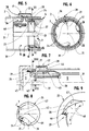
- FIG. 1 to 3 There is shown in Figures 1 to 3 a first embodiment of the present invention corresponding to a latch 23 defined by a lever 29 articulated around a substantially parallel axis 30 to the axis 31 of rotation of the winding shaft 2.
- this lever 29 includes a first arm 32 provided, in particular at its end 33, attachment means 34.
- attachment means 34 are designed able to cooperate with the means 24 forming a keeper, this in the locking position of said winding shaft 2 by the locking means 21 as shown in FIG. 3.
- Such a lever 29 also comprises a second arm 35, in particular located in the extension of the first arm 32, and defining said control means 28 intended to return said latch 23 in the inactive position.
- said latch 23 can be made integral with at least one of the bearings support 4 of the winding shaft 2.
- the latter 2 is, then, provided with said means 24 forming a keeper.
- said latch 23 is secured to said winding shaft 2 (in particular via the rotor 9), in particular at one 3 ends 3, 3 'of the latter 2 as shown in Figures 2 and 3.
- the means 24 forming keeper are defined by at least one stopper 26 that comprises a crown 25 defined at the level of at least one said support bearings 4 (in particular of the stator 7) of the shaft winding 2.
- the support bearing 4 comprising the means 24 forming a keeper, is constituted by a fixed part of the drive device 5 of the shaft winding 2.
- the roller shutter 1 can, advantageously but not limiting, present a drive device 5 of motorized type comprising a motor 6, in particular an electric motor.
- the crown 25 of the means 24 forming a keeper is constituted by a fixed part of this motor 6, more particularly by the stator 7 and / or the base 8 of the latter 6.
- FIG. 1 to 3 there is shown a mode of embodiment in which said latch 23 is defined by a lever 29 articulated around an axis 30 substantially parallel to the axis 31 of rotation of the winding shaft 2.
- FIGs 4 to 13 there are shown modes of embodiment corresponding to blocking means 21 comprising a latch 23 designed capable of adopting a radial movement by report to said winding shaft 2.
- This latch 23, in position active locking of the shaft 2, cooperates with means 24 forming a keeper (which includes said blocking means 21) defined by at least one stopper 26 that comprises a ring 25, coaxial with said winding shaft 2, and diameter approximately equal to that of this winding shaft 2.
- this crown 25 is defined at stator 7 of a support bearing 4 while said latch 23 is made integral with the rotor 9 of this bearing support 4.
- this crown 25 is defined at the level of the rotor 9 of a support bearing 4 while that said latch 23 is made integral with the stator 7 of this bearing support 4.
- Figures 4 to 9 show embodiments of the present invention for which said latch 23 is defined by an elastic blade 36 extending in a direction substantially parallel to the axis 31 of rotation of said shaft winding 2.
- Such an elastic blade 36 has a free end 37 at level of which said blade 36 is intended to cooperate with said means 24 forming a keeper, this in an active position means 21 for blocking the winding shaft 2.
- Such an elastic blade 36 also comprises means for control 28 which, as described above, are provided capable of cooperate with the control member 22 to bring back, in phase winding of the deck 11, said latch 23 in a position inactive locking means 21 of the winding shaft 2, this against the action of the return means 27.
- control means 28 are constituted by a control finger 38 extending radially with respect to said winding shaft 2.
- Such a control finger 38 is defined, in particular, by deformation of said blade 36 and is designed capable of cooperating, as the case may be, with the deck 11 (FIG. 4) or with a link 17 ( Figure 5).
- FIG 5 there is illustrated a winding shaft 2 in end position of deployment of the deck 11, said winding shaft 2 being defined by a tube 39 on which rolls up and from which takes place said apron 11.
- said elastic blade 36 is mounted inside said tube 39 of the winding shaft 2 and that the latter 2 has an orifice 40 through which is able to extend said control finger 38 to cooperate with a control member 22.
- said apron 11 is connected to said winding shaft 2 via a connecting member 17 capable of constituting said control member 22 with which said control finger 38 cooperates.
- FIG. 6 shows means 24 forming a keeper and adopting the shape of a crown 25 comprising, on its face internal, at least one radial projection 41 capable of defining a stopper 26.
- This radial projection 41 adopts, for example, a triangular shape with asymmetrical sides or may appear in the form of a hanging hook or the like.
- This crown 25 is, in fact, formed at a portion stator end 7 (oriented towards said rotor 9) a support bearing 4 while the rotor 9 of the latter 4 receives said elastic blade 36.
- a reverse design is, however possible.
- the crown 25 then being formed at level of an end portion of the rotor 9 (oriented in direction of said stator 7) of a support bearing 4 while the stator 7 of the latter 4 receives said elastic blade 36.
- the elastic blade 36 presents, according to a particular but non-limiting mode of realization, a round section.
- Such an elastic blade 36 can still be of the plane type.
- FIG. 7 to 9 there is shown an elastic blade 36 according to another embodiment and whose free end 37 is equipped with a shoe 42 comprising, on the one hand, a first portion 43 constituting control means 28 defined by a control button 44 able to cooperate with said apron 11 or, according to the preferred embodiment visible in FIG. 7, with said connecting member 17.
- This shoe 42 comprises, on the other hand, a second portion 45 able to cooperate with said means 24 forming a keeper, this in the shaft locking position winding 2 and end of deployment of said deck 11.
- Figure 8 a schematic view and partial of such cooperation.
- the second portion 45 of this shoe 42 adopts the form of at least one tooth 46 capable of cooperating with means 24 forming a keeper and defined by at least one recess 47 that comprises, on its internal face, a crown 25 formed at the level at least one of the support bearings 4.
- the tooth 46 of the second portion 45 of the shoe 42 has asymmetrical sides 48.
- Such an embodiment facilitates, from a hand, the support of this tooth 46 on the walls of the recess 47 in the active shaft locking position winding 2 and, on the other hand, the sliding of this tooth 46 out of this obviously 47, this in the direction of winding of the apron 11, in particular before the latch 23 reaches a inactive position under the impulse of said control member 22.
- said elastic blade 36 of Figures 7 to 9 can, again, be mounted inside a tube 39 forming the winding shaft 2 and that the latter has an orifice at the through which is adapted to extend said control means 28 to cooperate with a control member 22.
- the crown 25 is, in fact, formed at an end portion of the stator 7 (oriented towards said rotor 9) of a support bearing 4 while the rotor 9 of the latter 4 receives said blade elastic 36.
- a reverse design is, however possible.
- the crown 25 then being formed at the level an end portion of the rotor 9 (oriented in the direction said stator 7) of a support bearing 4 while the stator 7 of the latter 4 receives said elastic blade 36.
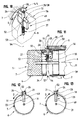
- FIGS. 10 to 13 Another embodiment has been represented in FIGS. 10 to 13.
- said blocking means 21 defined by a latch 23 and by means 24 forming a keeper which can take the form of a crown 25 having the characteristics described above.
- such a latch 23 is defined by a blade 49 made integral with said roller shutter 1 by means of joining 50.
- This blade 49 extends in a direction substantially parallel to the axis 31 of the winding shaft 2 and has a longitudinal edge 51, on the one hand, oriented in direction of means 24 forming a keeper and, on the other hand, suitable for cooperate with the latter 24 in the direction of development and in deployment limit switch for said deck 11.
- this blade 49 comprises, at this edge longitudinal 51, a chamfer 52 designed capable of facilitating the disengagement of said blade 49 from the means 24 forming a keeper, this in the direction of winding of said apron 11, from the end position of the latter 11.
- a chamfer 52 designed capable of facilitating the disengagement of said blade 49 from the means 24 forming a keeper, this in the direction of winding of said apron 11, from the end position of the latter 11.
- the securing means 50 of the blade 49 are designed capable of ensure a reversible mounting of the latter 49, this in view to allow proper positioning of the chamfer 52 of this blade 49 relative to the means 24 forming a keeper.
- joining means 50 allow, advantageously, to modify the position of said blade 49 by so as to adapt to the direction of unwinding D of the tree winding 2 as shown in Figures 12 and 13.
- such means of joining 50 comprise a pivot 53 allowing a 180 ° pivoting of said blade 49, this along an axis 54 perpendicular to the axis 31 of said winding shaft 2.
- Said pivot 53 then makes it possible to turn over this blade 49 to move from a position shown in FIG. 12 to a position shown in Figure 13, and vice versa.
- Another characteristic of the invention consists in that the securing means 50 of said blade 49 are designed capable to authorize an axial displacement of this blade 49 relative to the roller shutter 1, this along the pivot axis 54 thereof 49.
- the blade 49 defining said latch 23, is subjected to elastic return means 27 capable of repelling it in a active position for locking the winding shaft 2 in which this blade 49 is in cooperation with the means 24 forming a keeper.
- such elastic return means 27 are associated with the means of joining 50 of the blade 49 to said rolling shutter 1 and are able to repel this blade 49 towards said means 24 forming a keeper, this through a axial movement of this blade 49 along its axis 54 of pivoting.
- return means 27 can, here again, be defined by a return spring or the like.
- said latch 23 is completed by control means 28, associated with the blade 49, defined by a control finger 38, and provided capable of cooperating with said control member 22, the latter 22 adopting, by example, the shape of a blade 12 of the deck 11 or of a link 17 as mentioned above.
- the blade 49, defining said latch 23, comprises means capable of controlling its pivoting.
- pivot control means are defined by said control finger 38 associated with said blade 49 and suitable to cooperate with said control member 22 to bring back and maintain said blade 49 in the inactive position against the action return means 27.
- said control finger 38 comprises means for receiving (in particular a groove) of a tool, in particular a screwdriver or the like, intended to ensure the inversion of said blade 49.
- control finger 38 must be made available for such intervention. Also and as shown in FIG. 11, this control finger 38 can be located at a gap 57 defined between the bearing support 4 (in particular its stator 7) and the winding shaft 2.
- Such a control finger 38 can also be made accessible. through an orifice that includes said winding shaft 2 inside which such a blade can be mounted 49 (solution not shown).
- said blade 49 is made integral of said roller shutter 1 by means of solidarity 50.
- said blade 49 is made integral with stator 7 of a bearing support 4 while the means 24 forming a keeper are defined by at least one stopper 26 which comprises a crown 25 (in particular at the level of its internal face) formed at the level of a end portion of the rotor 9 (oriented towards said stator 7) of this support bearing 4.
- said blade 49 is made integral with the rotor 9 of a support bearing 4 while the means 24 forming a keeper are defined by at least one stop stop 26 that comprises a crown 25 (in particular at its inner face) formed at an end portion of the stator 7 (oriented towards said rotor 9) of this bearing support 4.
- this blade 49 can be made integral with a console 55 that comprises a wheel 56, on the one hand, engaged inside said winding shaft 2 defined by a tube 39 and, on the other hand, associated with the rotor 9 of a support bearing 4 or defining such rotor 9.
- Figures 12 and 13 are represented, block diagrams corresponding to embodiments using a support bearing 4 having for one (FIG. 12) a sense of unwinding D in a certain direction and for the other ( Figure 13) a direction of unwinding D in the opposite direction.
- a reversible blade 49 allows, by simple pivoting of this blade 49, to adapt to the direction of unwinding D of such a support bearing 4.
- such a support bearing 4 comprises a tubular end piece 10, at least in part engaged inside said winding shaft 2, and receiving at least part of said blocking means 21.
- Au level of this tubular nozzle 10 is defined said rotor 9 in taken with said winding shaft 2, or even (and preferably) at least part of said stator 7.
- said tubular end piece 10 is engaged inside said shaft winding 2 and has a rotor 9 which is rendered integral with said latch 23 while the crown 25 means 24 forming a keeper is defined at the end portion of said stator 7 at least partially engaged in said shaft winding 2.
- said tree winding 2 can be provided with an orifice capable of being crossed by a control means 28 for its cooperation with a control member 22.
- the support bearing 4 receiving said blocking means 21 is constituted by said drive device 5, in particular of motorized type 6, of said winding shaft 2.
- Figures 12 and 13 show block diagrams corresponding to embodiments using a motorized drive device 5 comprising for one (FIG. 12) a motor 6 of the type on the right with a sense of unwinding D in a certain direction and for the other (figure 13) a motor 6 of the type on the left with a direction of unwinding D in an opposite direction.
- Such blocking means 21 can, moreover and so advantageous, equip either a rolling shutter 1 equipped a drive device 5 of manual or motorized type.
Landscapes
- Engineering & Computer Science (AREA)
- Structural Engineering (AREA)
- Architecture (AREA)
- Civil Engineering (AREA)
- Operating, Guiding And Securing Of Roll- Type Closing Members (AREA)
Abstract
Description
Claims (21)
- Volet roulant (1) comportant un arbre d'enroulement (2) sur lequel s'enroule et à partir duquel se déroule un tablier (11), défini par une succession de lames (12), et raccordé, directement ou par l'intermédiaire d'un organe de liaison (17), audit arbre d'enroulement (2), ce dernier (2) étant, d'une part, maintenu en rotation à ses extrémités (3, 3') par des paliers support (4) comportant un rotor (9) et un stator (7) et, d'autre part, actionné par l'intermédiaire d'un dispositif d'entraínement (5), ledit volet (1) étant complété par des moyens (21) aptes à assurer le blocage en rotation dudit arbre d'enroulement (2) dans le sens du déroulement et en fin de course de déploiement du tablier (11), de tels moyens de blocage (21) étant conçus aptes, d'une part, à être maintenus dans une position inactive et, d'autre part et au contraire, à adopter une position active de blocage dudit arbre d'enroulement sous l'impulsion d'un organe de commande (22), caractérisé par le fait que lesdits moyens de blocage (21) sont définis par un loquet (23) conçu apte à adopter un mouvement radial par rapport audit arbre d'enroulement (2) et qui, en position active de blocage, coopère avec des moyens (24) formant gâche, que comportent lesdits moyens de blocage (21), et définis par au moins une butée d'arrêt (26) que comporte une couronne (25), coaxiale audit arbre d'enroulement (2), de diamètre environ égal à celui de ce dernier (2) et définie au niveau, soit du stator (7), soit du rotor (9) d'un palier support (4) tandis que ledit loquet (23) est rendu solidaire, respectivement, dudit rotor (9) ou dudit stator (7) de ce palier support (4).
- Volet roulant (1) selon la revendication 1, caractérisé par le fait que le loquet (23) est soumis à des moyens (27) de rappel élastique aptes à le repousser dans une position active de blocage de l'arbre d'enroulement (2) dans laquelle ledit loquet (23) coopère avec les moyens (24) formant gâche.
- Volet roulant (1) selon la revendication 2, caractérisé par le fait que le loquet (23) est complété par des moyens de commande (28) associés à ce dernier (23) et prévus aptes à coopérer avec ledit organe de commande (22) pour ramener, en phase d'enroulement du tablier (11), ledit loquet (23) en position inactive de blocage contre l'action des moyens (27) de rappel élastique.
- Volet roulant (1) selon la revendication 3, caractérisé par le fait que le loquet (23) est monté à l'intérieur dudit arbre d'enroulement (2), ce dernier (2) comportant un orifice (40) au travers duquel sont aptes à s'étendre lesdits moyens (28) de commande en vue de coopérer avec ledit organe de commande (22).
- Volet roulant (1) selon l'une quelconque des revendications 1 à 4, caractérisé par le fait que le loquet (23) est défini par une lame élastique (36) s'étendant dans une direction sensiblement parallèle à l'axe (31) de l'arbre d'enroulement (2) et comportant une extrémité libre (37) au niveau de laquelle ladite lame élastique (36) coopère avec lesdits moyens (24) formant gâche.
- Volet roulant (1) selon les revendications 3 et 5, caractérisé par le fait que les moyens (28) de commande sont constitués par un doigt de commande (38), défini par déformation de ladite lame élastique (36), s'étendant radialement par rapport audit arbre d'enroulement (2) et apte à coopérer avec ledit organe de commande (22).
- Volet roulant (1) selon l'une quelconque des revendications 5 ou 6, caractérisé par le fait que l'extrémité libre (37) de ladite lame élastique (36) coopère, en position de blocage, avec au moins une saillie radiale (41), notamment de forme triangulaire à pans asymétriques, constituant une butée d'arrêt (26) et définie au niveau de la couronne (25) des moyens (24) formant gâche.
- Volet roulant (1) selon l'une quelconque des revendications 5 ou 6, caractérisé par le fait que l'extrémité libre (37) de la lame élastique (36) est équipée d'un sabot (42) comportant, d'une part, une première portion (43) constituant des moyens de commande (28) définis par un bouton de commande (44) apte à coopérer avec ledit organe de commande (22) et, d'autre part, une seconde portion (45) apte à coopérer avec lesdits moyens (24) formant gâche, en position active de blocage de l'arbre d'enroulement (2).
- Volet roulant (1) selon la revendication 8, caractérisé par le fait que la seconde portion (45) de ce sabot (42) adopte la forme d'au moins une dent (46) apte à coopérer avec au moins un évidement (47) constituant une butée d'arrêt (26) définie au niveau de la couronne (25) des moyens (24) formant gâche.
- Volet roulant (1) selon la revendication 9, caractérisé par le fait que la dent (46) que comporte le sabot (42) présente des pans (48) asymétriques en vue de faciliter, d'une part, la prise d'appui de cette dent (46) sur les parois de l'évidement (47) en position active de blocage de l'arbre d'enroulement (2) et, d'autre part, le glissement de cette dent (46) hors de cet évidemment (47), ceci dans le sens d'enroulement du tablier (11), notamment avant que le loquet (23) atteigne une position inactive sous l'impulsion dudit organe de commande (22).
- Volet roulant (1) selon l'une quelconque des revendications 1 à 4, caractérisé par le fait que le loquet (23) est défini par une lame (49) rendue solidaire dudit volet roulant (1) par l'intermédiaire de moyens de solidarisation (50), ladite lame (49) s'étendant selon une direction sensiblement parallèle à l'axe (31) de l'arbre d'enroulement (2) et comportant un bord longitudinal (51), d'une part, pourvu d'un chanfrein (52) et, d'autre part, au travers duquel cette lame (49) coopère avec lesdits moyens (24) formant gâche, ceci dans le sens de déroulement et en fin de course de déploiement dudit tablier (11).
- Volet roulant (1) selon la revendication 11, caractérisé par le fait que lesdits moyens de solidarisation (50) de la lame (49) sont conçus aptes à autoriser un montage réversible de cette dernière (49) sur ledit volet roulant (1) en vue de permettre un positionnement approprié du chanfrein (52) de cette lame (49) par rapport aux moyens (24) formant gâche.
- Volet roulant (1) selon la revendication 12, caractérisé par le fait que les moyens de solidarisation (50) comportent un pivot (53) autorisant un pivotement à 180° de ladite lame (49), ceci selon un axe (54) perpendiculaire à l'axe (31) dudit arbre d'enroulement (2).
- Volet roulant (1) selon la revendication 13, caractérisé par le fait que les moyens de solidarisation (50) sont, d'une part, conçus aptes autoriser un déplacement axial de ladite lame (49) selon son axe (54) de pivotement et, d'autre part, associés à des moyens de rappel élastiques (27) aptes à repousser ladite lame (49), axialement et selon son axe (54) de pivotement, dans une position active de blocage de l'arbre d'enroulement (2) dans laquelle ladite lame (49) est en coopération avec lesdits moyens (24) formant gâche.
- Volet roulant (1) selon la revendication 14, caractérisé par le fait que ladite lame (49) comporte des moyens de commande de son pivotement définis par des moyens (28) de commande destinés à coopérer avec ledit organe de commande (22) pour ramener, en phase d'enroulement du tablier (11), ledit loquet (23) en position inactive contre l'action des moyens (27) de rappel élastique.
- Volet roulant (1) selon l'une quelconque des revendications 1 à 10, caractérisé par le fait que la couronne (25), d'une part, est définie au niveau d'une portion d'extrémité du stator (7) d'un palier support (4), orientée en direction du rotor (9) de ce palier support (4) et, d'autre part, présente une face externe au niveau de laquelle est définie au moins une butée d'arrêt (26) tandis que ledit loquet (23) est rendu solidaire dudit rotor (9).
- Volet roulant (1) selon l'une quelconque des revendications 1 à 15, caractérisé par le fait que la couronne (25) est définie au niveau d'une portion d'extrémité du stator (7), respectivement du rotor (9), d'un palier support (4), ladite portion d'extrémité étant orientée en direction dudit rotor (9), respectivement dudit stator (7), de ce palier support (4), cette couronne présentant une face interne au niveau de laquelle est définie au moins une butée d'arrêt (26) tandis que ledit loquet (23) est rendu solidaire dudit rotor (9), respectivement dudit stator (7).
- Volet roulant (1) selon l'une quelconque des revendications précédentes, caractérisé par le fait que le palier support (4) comporte un embout tubulaire (10), au moins en partie engagé à l'intérieur dudit arbre d'enroulement (2), et au niveau duquel est défini ledit rotor (9) en prise avec ledit arbre d'enroulement (2) voire une partie au moins dudit stator (7), cet embout tubulaire (10) recevant une partie au moins desdits moyens (21) de blocage.
- Volet roulant (1) selon les revendications 17 et 18 , caractérisé par le fait que ledit embout tubulaire est engagé à l'intérieur dudit arbre d'enroulement (2) et comporte un rotor (9) duquel est rendu solidaire ledit loquet (23) tandis que la couronne (25) des moyens (24) formant gâche est définie au niveau de la portion d'extrémité dudit stator (7).
- Volet roulant (1) selon l'une quelconque des revendications précédentes, caractérisé par le fait que ledit organe de commande (22) est défini, soit par au moins une des lames (12) du tablier (11), soit par un organe de liaison (17) adoptant la forme d'un bande souple (18), d'une sangle, d'une lame métallique ou autre et comportant, d'une part, une première extrémité (19) reliée audit arbre d'enroulement (2) sur lequel est à même de s'enrouler ledit organe de liaison (17) et, d'autre part, une seconde extrémité (20) reliée audit tablier (11), notamment au niveau d'une première lame (16) équipant ce dernier (11).
- Volet roulant (1) selon l'une quelconque des revendications précédentes, caractérisé par le fait que le palier support (4) recevant lesdits moyens (21) de blocage est constitué par ledit dispositif d'entraínement (5), notamment de type motorisé, dudit arbre d'enroulement (2).
Applications Claiming Priority (4)
| Application Number | Priority Date | Filing Date | Title |
|---|---|---|---|
| FR0009018A FR2811704B1 (fr) | 2000-07-11 | 2000-07-11 | Volet roulant comportant des moyens de blocages de l'arbre d'enroulement de son tablier |
| FR0009018 | 2000-07-11 | ||
| FR0016079 | 2000-12-11 | ||
| FR0016079A FR2811705B3 (fr) | 2000-07-11 | 2000-12-11 | Volet roulant comportant des moyens de blocage de l'arbre d'enroulement de son tablier |
Publications (2)
| Publication Number | Publication Date |
|---|---|
| EP1172517A1 true EP1172517A1 (fr) | 2002-01-16 |
| EP1172517B1 EP1172517B1 (fr) | 2003-05-02 |
Family
ID=26212527
Family Applications (1)
| Application Number | Title | Priority Date | Filing Date |
|---|---|---|---|
| EP20010440210 Expired - Lifetime EP1172517B1 (fr) | 2000-07-11 | 2001-07-05 | Volet roulant comportant des moyens de blocage de l'arbre d'enroulement de son tablier. |
Country Status (4)
| Country | Link |
|---|---|
| EP (1) | EP1172517B1 (fr) |
| DE (1) | DE60100228T2 (fr) |
| ES (1) | ES2194824T3 (fr) |
| FR (1) | FR2811705B3 (fr) |
Cited By (2)
| Publication number | Priority date | Publication date | Assignee | Title |
|---|---|---|---|---|
| FR2961248A1 (fr) * | 2010-06-15 | 2011-12-16 | Franciaflex | Store motorise mono-commande |
| CN110614904A (zh) * | 2019-09-25 | 2019-12-27 | 董克思 | 一种锁止结构及遮阳帘收卷器 |
Citations (1)
| Publication number | Priority date | Publication date | Assignee | Title |
|---|---|---|---|---|
| CH353276A (fr) * | 1958-03-14 | 1961-03-31 | Perrier Sa | Dispositif destiné à limiter le déroulement d'un volet roulant |
-
2000
- 2000-12-11 FR FR0016079A patent/FR2811705B3/fr not_active Expired - Fee Related
-
2001
- 2001-07-05 ES ES01440210T patent/ES2194824T3/es not_active Expired - Lifetime
- 2001-07-05 DE DE2001600228 patent/DE60100228T2/de not_active Expired - Fee Related
- 2001-07-05 EP EP20010440210 patent/EP1172517B1/fr not_active Expired - Lifetime
Patent Citations (1)
| Publication number | Priority date | Publication date | Assignee | Title |
|---|---|---|---|---|
| CH353276A (fr) * | 1958-03-14 | 1961-03-31 | Perrier Sa | Dispositif destiné à limiter le déroulement d'un volet roulant |
Cited By (4)
| Publication number | Priority date | Publication date | Assignee | Title |
|---|---|---|---|---|
| FR2961248A1 (fr) * | 2010-06-15 | 2011-12-16 | Franciaflex | Store motorise mono-commande |
| EP2397645A1 (fr) * | 2010-06-15 | 2011-12-21 | Franciaflex | Store motorisé mono-commandé |
| CN110614904A (zh) * | 2019-09-25 | 2019-12-27 | 董克思 | 一种锁止结构及遮阳帘收卷器 |
| CN110614904B (zh) * | 2019-09-25 | 2024-12-20 | 董克思 | 一种锁止结构及遮阳帘收卷器 |
Also Published As
| Publication number | Publication date |
|---|---|
| DE60100228T2 (de) | 2004-04-08 |
| EP1172517B1 (fr) | 2003-05-02 |
| DE60100228D1 (de) | 2003-06-05 |
| FR2811705B3 (fr) | 2002-08-09 |
| FR2811705A1 (fr) | 2002-01-18 |
| ES2194824T3 (es) | 2003-12-01 |
Similar Documents
| Publication | Publication Date | Title |
|---|---|---|
| FR2666842A1 (fr) | Dispositif d'enroulement a moteur tubulaire pour stores, volets roulants ou similaires. | |
| WO2005026473A1 (fr) | Dispositif et procede pour recouvrir et decouvrir une surface par un element de couverture enroulable | |
| EP0730080B1 (fr) | Dispositif de fixation d'un arbre de volet roulant | |
| EP1172517B1 (fr) | Volet roulant comportant des moyens de blocage de l'arbre d'enroulement de son tablier. | |
| FR2779474A1 (fr) | Store a enrouleur a boitier deformable | |
| EP1676013B1 (fr) | Dispositif de commande de l'ouverture d'un element mobile tel qu'une trappe de desenfumage | |
| EP3293344B1 (fr) | Dispositif d'enroulement/déroulement d'un volet roulant | |
| WO2019162380A1 (fr) | Système d'entrainement en rotation d'un organe d'enroulement | |
| EP1977070B1 (fr) | Dispositif de support pour volet roulant et ensemble de volet roulant a monter avec un tel dispositif | |
| EP1026363B1 (fr) | Dispositif anti-relevage de sécurité de volet roulant | |
| FR2811704A1 (fr) | Volet roulant comportant des moyens de blocages de l'arbre d'enroulement de son tablier | |
| FR2966189A1 (fr) | Dispositif de blocage d'une barre de charge d'un ecran et installation de fermeture ou de protection solaire equipee d'un tel dispositif de blocage | |
| EP1589184B1 (fr) | Volet roulant comportant un dispositif de blocage axial d'un tronçon d'axe emboité dans une joue support | |
| BE1010525A4 (fr) | Structure de protection. | |
| FR3014937B1 (fr) | Fin de course d'enroulement ou de deroulement de tablier de systeme d'occultation | |
| FR2614928A1 (fr) | Volet roulant pour porte, fenetre et autres ouvertures | |
| FR2785942A1 (fr) | Joue a multiples fonctions pour caisson de volet roulant avec tablier a lames articulees | |
| EP1157870A1 (fr) | Store à enrouleur à barre de tirage mobile axialement | |
| EP1106776A1 (fr) | Enrouleur de sangle, mécanisme de manoeuvre d'un volet ou store roulant comprenant un tel enrouleur et procédé de réglage de la tension du ressort d'un tel enrouleur | |
| FR3032998A1 (fr) | Procede d'assemblage d'une installation de fermeture ou de protection solaire, systeme de support et installation. | |
| EP0775605A1 (fr) | Store pare-soleil à mécanisme de déploiement par bielletes pivotantes | |
| EP0646070A1 (fr) | Store a enrouleur motorise pour baie galbee | |
| EP0965723A1 (fr) | Volet roulant pour porte, fenêtre ou analogue | |
| EP0945585A1 (fr) | Volet roulant comportant un dispositif d'entrainement manuel | |
| FR2744758A3 (fr) | Mecanisme de commande de volet roulant |
Legal Events
| Date | Code | Title | Description |
|---|---|---|---|
| PUAI | Public reference made under article 153(3) epc to a published international application that has entered the european phase |
Free format text: ORIGINAL CODE: 0009012 |
|
| AK | Designated contracting states |
Kind code of ref document: A1 Designated state(s): AT BE CH CY DE DK ES FI FR GB GR IE IT LI LU MC NL PT SE TR Kind code of ref document: A1 Designated state(s): DE ES FR IT |
|
| AX | Request for extension of the european patent |
Free format text: AL;LT;LV;MK;RO;SI |
|
| 17P | Request for examination filed |
Effective date: 20011124 |
|
| GRAG | Despatch of communication of intention to grant |
Free format text: ORIGINAL CODE: EPIDOS AGRA |
|
| 17Q | First examination report despatched |
Effective date: 20020307 |
|
| GRAG | Despatch of communication of intention to grant |
Free format text: ORIGINAL CODE: EPIDOS AGRA |
|
| GRAH | Despatch of communication of intention to grant a patent |
Free format text: ORIGINAL CODE: EPIDOS IGRA |
|
| GRAH | Despatch of communication of intention to grant a patent |
Free format text: ORIGINAL CODE: EPIDOS IGRA |
|
| AKX | Designation fees paid |
Free format text: DE ES FR IT |
|
| GRAA | (expected) grant |
Free format text: ORIGINAL CODE: 0009210 |
|
| AK | Designated contracting states |
Designated state(s): DE ES FR IT |
|
| REF | Corresponds to: |
Ref document number: 60100228 Country of ref document: DE Date of ref document: 20030605 Kind code of ref document: P |
|
| REG | Reference to a national code |
Ref country code: IE Ref legal event code: FG4D Free format text: FRENCH |
|
| REG | Reference to a national code |
Ref country code: IE Ref legal event code: FD4D Ref document number: 1172517E Country of ref document: IE |
|
| PLBE | No opposition filed within time limit |
Free format text: ORIGINAL CODE: 0009261 |
|
| STAA | Information on the status of an ep patent application or granted ep patent |
Free format text: STATUS: NO OPPOSITION FILED WITHIN TIME LIMIT |
|
| 26N | No opposition filed |
Effective date: 20040203 |
|
| PGFP | Annual fee paid to national office [announced via postgrant information from national office to epo] |
Ref country code: FR Payment date: 20050725 Year of fee payment: 5 |
|
| PGFP | Annual fee paid to national office [announced via postgrant information from national office to epo] |
Ref country code: DE Payment date: 20060706 Year of fee payment: 6 |
|
| PGFP | Annual fee paid to national office [announced via postgrant information from national office to epo] |
Ref country code: IT Payment date: 20060731 Year of fee payment: 6 |
|
| PGFP | Annual fee paid to national office [announced via postgrant information from national office to epo] |
Ref country code: ES Payment date: 20060825 Year of fee payment: 6 |
|
| REG | Reference to a national code |
Ref country code: FR Ref legal event code: ST Effective date: 20070330 |
|
| PG25 | Lapsed in a contracting state [announced via postgrant information from national office to epo] |
Ref country code: FR Free format text: LAPSE BECAUSE OF NON-PAYMENT OF DUE FEES Effective date: 20060731 Ref country code: DE Free format text: LAPSE BECAUSE OF NON-PAYMENT OF DUE FEES Effective date: 20080201 |
|
| REG | Reference to a national code |
Ref country code: ES Ref legal event code: FD2A Effective date: 20070706 |
|
| PG25 | Lapsed in a contracting state [announced via postgrant information from national office to epo] |
Ref country code: ES Free format text: LAPSE BECAUSE OF NON-PAYMENT OF DUE FEES Effective date: 20070706 |
|
| PG25 | Lapsed in a contracting state [announced via postgrant information from national office to epo] |
Ref country code: IT Free format text: LAPSE BECAUSE OF NON-PAYMENT OF DUE FEES Effective date: 20070705 |