EP1172308B1 - Device and method for handling and emptying containers destined for the waste collection - Google Patents
Device and method for handling and emptying containers destined for the waste collection Download PDFInfo
- Publication number
- EP1172308B1 EP1172308B1 EP01116183A EP01116183A EP1172308B1 EP 1172308 B1 EP1172308 B1 EP 1172308B1 EP 01116183 A EP01116183 A EP 01116183A EP 01116183 A EP01116183 A EP 01116183A EP 1172308 B1 EP1172308 B1 EP 1172308B1
- Authority
- EP
- European Patent Office
- Prior art keywords
- container
- coupling
- rod
- previous
- door
- Prior art date
- Legal status (The legal status is an assumption and is not a legal conclusion. Google has not performed a legal analysis and makes no representation as to the accuracy of the status listed.)
- Expired - Lifetime
Links
- 239000002699 waste material Substances 0.000 title claims abstract description 32
- 238000000034 method Methods 0.000 title claims description 5
- 230000008878 coupling Effects 0.000 claims abstract description 86
- 238000010168 coupling process Methods 0.000 claims abstract description 86
- 238000005859 coupling reaction Methods 0.000 claims abstract description 86
- 238000006073 displacement reaction Methods 0.000 claims description 11
- 230000000295 complement effect Effects 0.000 claims description 4
- 230000036961 partial effect Effects 0.000 description 4
- 230000000284 resting effect Effects 0.000 description 4
- 230000002829 reductive effect Effects 0.000 description 3
- 238000004519 manufacturing process Methods 0.000 description 2
- 230000009467 reduction Effects 0.000 description 2
- 230000002441 reversible effect Effects 0.000 description 2
- 229910000831 Steel Inorganic materials 0.000 description 1
- 230000009471 action Effects 0.000 description 1
- 230000005540 biological transmission Effects 0.000 description 1
- 238000001514 detection method Methods 0.000 description 1
- 239000011521 glass Substances 0.000 description 1
- 230000000670 limiting effect Effects 0.000 description 1
- 239000000123 paper Substances 0.000 description 1
- 229920003023 plastic Polymers 0.000 description 1
- 239000004033 plastic Substances 0.000 description 1
- 239000010959 steel Substances 0.000 description 1
- 238000002604 ultrasonography Methods 0.000 description 1
Images



Classifications
-
- B—PERFORMING OPERATIONS; TRANSPORTING
- B65—CONVEYING; PACKING; STORING; HANDLING THIN OR FILAMENTARY MATERIAL
- B65F—GATHERING OR REMOVAL OF DOMESTIC OR LIKE REFUSE
- B65F1/00—Refuse receptacles; Accessories therefor
- B65F1/14—Other constructional features; Accessories
- B65F1/1426—Housings, cabinets or enclosures for refuse receptacles
- B65F1/1447—Housings, cabinets or enclosures for refuse receptacles located underground
-
- B—PERFORMING OPERATIONS; TRANSPORTING
- B65—CONVEYING; PACKING; STORING; HANDLING THIN OR FILAMENTARY MATERIAL
- B65F—GATHERING OR REMOVAL OF DOMESTIC OR LIKE REFUSE
- B65F1/00—Refuse receptacles; Accessories therefor
- B65F1/12—Refuse receptacles; Accessories therefor with devices facilitating emptying
- B65F1/125—Features allowing the receptacle to be lifted and emptied by its bottom
Definitions
- the present invention concerns a device and a method for handling and emptying containers for waste collection, in particular for differentiated refuse collection.
- the containers for waste collection in particular for differentiated refuse collection, for example glass, paper, plastics, etc. are manufactured with the loading openings substantially in the upper part while the emptying is carried out through an opening provided in the lower part.
- They are generally manufactured in a bell-shaped or with a substantially quadrangular and/or rectangular section.
- the motor vehicles used for handling and emptying the contents of these containers are provided with a body to contain the waste and a multi-axis articulated and revolving mechanical arm, hydraulically-controlled, placed between the body and the vehicle's cabin to which is connected a device for coupling the container and for placing it above the body in order to empty the waste contained in it.
- the US 5 014 870 patent discloses a container that presents, centrally and on its upper part, some appropriate means for coupling it through an appropriate device for lifting and displacing it for the next emptying of the contents present inside it.
- These coupling means provide a first coupling element that consists in a bushing fixed centrally and securely to the upper part of the container and that presents a flange on its top.
- a square section bar slides inside the bushing; its upper end, protruding from the container, presents a flange while the other end, inside the container, is connected to the tie rods that are fixed to the opened bottom of the container.
- These tie rods are manufactured with flexible elements, for example steel ropes that are released, i.e. loose, when the container is resting on the ground.
- the bar has a square section to avoid circular movements that could make the ropes overlap, with ensuing problems when the bottom of the container must be closed and/or opened.
- the sliding bar presents a ring placed immediately under the flange present at its upper end; the ring has the function to stop the entry of the bar in the container and to allow the coupling of the sliding bar, when the container is resting on the ground, preventing the flange of the bar to rest on the flange of the bushing of the container.
- the bottom of the container is generally divided in two equal and symmetric parts that open outward as to the container.
- a coupling device is associated to this container connected to the articulated arm of a vehicle.
- the device presents at least two symmetrically opposite levers each with a hook at an end.
- the levers controlled by hydraulic actuators, can oscillate and, with the hook present at their end, couple under the flange present on the bushing fixed to the container. This coupling allows the handling of the container.
- the device also comprises, in middle and vertically position, a hydraulic actuator that is fixed with one end to the upper part of the coupling device.
- the other end of the hydraulic actuator, the sliding one presents a beam to which are articulated in a symmetrically opposite position at least two levers each with a hook at one end.
- the levers, controlled by hydraulic actuators, can oscillate and, with the hook present at their end, couple under the flange present on the upper end of the sliding bar. This coupling allows the handling of the sliding bar for closing and/or opening the lower part of the container.
- the actuators are activated for the levers present on the beam in such a way that they couple the flange of the sliding bar with their hook.
- the actuators for the movement of the levers connected to the body of the coupling device are also activated in such a way that they couple the flange of the bushing fixed to the container.
- the middle actuator is activated: in this way the sliding bar translates upwards in such a way that the tie rods inside the container are pulled and kept in this position in order not to allow the lower part of the container to open during the lifting.
- the container can be lifted and placed above the body of the vehicle ready for emptying its contents.
- the middle hydraulic actuator is activated to translate downwards the sliding bar in order to release the tie rods and open the lower part of the container for emptying.
- the reverse must be carried out: activate the internal actuator in order to translate upwards the sliding bar and close the bottom of the container, place the container back on the road, activate the middle actuator to translate the sliding bar downwards so that it does not protrude excessively from the container when the coupling device is removed, activate the actuators to release the levers from the bushing flange fixed to the container as well as from the flange of the sliding bar, lift the coupling device, move the vehicle to the next container to be emptied.
- this container and this device require a variety of operations for coupling, emptying and releasing the container and precisely:
- this device presents a complex realisation both from the operational point of view and as it is manufacture, see for example the number of the hydraulic actuators and of the coupling levers that increase its dimension and costs.
- the vertical movement of the sliding bar in order to put the tie rods in traction and keep the bottom of the container closed when the latter is lifted from the ground requires that the sliding bar executes a path greater than the one made if the tie rods were normally in traction and therefore as a result has also a greater length.
- a longer path of the sliding bar requires therefore that also the hydraulic actuator in charge of its movement is fit for the amplitude of this path, with an increase of the realisation costs.
- a first aim of the present invention is to indicate a coupling device, which reduces the time of the complete emptying operation of a waste container.
- a further aim of the present invention is to indicate a coupling device that may be manufactured with less mechanical components and small size than the known art.
- a further aim of the present invention is to indicate a container for waste collection, for which the coupling device may be used with advantages for what concerns functions and user-friendly.
- Fig. 1-4 show schematically a cross-section of a handling device and a container for said device, in the first coupling position for lifting the container and in the second coupling position for emptying the container, a partial cross-section in an oversized scale of the device in the first and second coupling position of the container for said device, where number 1 indicates the coupling device and number 2 indicates a container resting on the ground and fit for working together with the device 1.
- the container 2 presents in the middle of its upper part a cylindrical bushing 3 with one end fixed securely to the container and to the other end is fixed a ring 4.
- the ring 4 presents the lower surface flat and the upper surface in a truncated cone shape; the ring 4 presents also a greater diameter than the cylindrical bushing 3 in order to obtain a coupling step with the bushing itself.
- Number 5 indicates a tubular rod passing and sliding inside the bushing 3; on the upper end of the rod 5 a pin 6 is hammered; the pin 6 presents a round head shaped protruding from the rod 5 and whose diameter is essentially the same as that of the rod.
- Each lever 8 and 9, is articulated with a bracket indicated with 10; these brackets are articulated in a vertical position with a plate 11 fixed on the internal part of the upper wall of the container 2, in such a way as to execute an angular movement around their articulation axis.
- Each levers 8 and 9 presents two straight parts indicated with 8', 8", 9' and 9" respectively; the 8" and 9" straight parts are tilted about of 20° with respect to the corresponding 8' and 9'straight parts.
- each 8" and 9" straight part is articulated with a pair of tie rods indicated with 12, 12A and 13, 13A respectively, which are articulated with one of the two doors 14 and 15 closing the bottom of the container 2;
- Fig. 1 and 2 show only the tie rods 12 and 13 and the door 14, because the tie rods 12A and 13A and the door 15 are placed symmetrically to the tie rods 12 and 13 and to the door 14 in the part of the container 2 not visible in its cross-section represented in Fig. 1 and 2 (see Fig. 12 as an example).
- the point of articulation of the levers 8 and 9 with the bracket 10 is such that a downward or upward movement of the levers 8 and 9 by means of the bracket 7, through the tubular rod 5, corresponds to an opposite movement having a greater amplitude than the ends of the straight parts 8" and 9"; the difference between the width of the movement of the tubular rod 5 and that of the ends of the straight parts 8" and 9" is given by the ratio existing between the point of articulation to the bracket 10 of the levers 8 and 9 and their two ends.
- bracket 7 corresponds to twice the upward or downward movement of the tie rods.
- the amplitude of the tie rod movement may be changed.
- the container 2 presents also an opening, not shown, placed usually in the upper part, for inserting waste inside the container, which can differ in shape, for example round for containers for bottles, tins and similar, or rectangular or square, with or without lid.
- the coupling device 1 presents a body 16, to the lower part of body 16 are pivoted of the levers 17 that present a small tooth 18 for coupling the ring 4 of the container 2 for its displacement for dumping.
- the lower surface of the body 16 presents a complementary shape to the ring 4 on which it is coupled during the coupling phase of the container 2 as described later.
- the other end of the hydraulic actuator 20 is fixed to the upper part of the body 16.
- a piston 21 is fixed to rod 20A of the hydraulic actuator 20, the external diameter of this piston is substantially equal to the internal diameter of the tubular element 19 and within which it can slide under the action of the hydraulic actuator 20.
- the lower base of the piston 21 presents a shape complementary to that of the end of pin 6 with which it is coupled.
- the levers 17 present, with views from the top according to Fig. 6, substantially a "C" shape, and they are mounted symmetrically between them with the upper and lower portions of "C", indicated with 17A and 17B respectively, which face each other and couple sideways to the body 16.
- a mechanical actuator 22 is placed vertically between the two portions 17A and 17B of the levers 17 facing each other; this mechanical actuator 22 presents two bases 23A and 23B joined by a cylindrical pin 24 having a diameter smaller than the two bases.
- the lower base 23B of the mechanical actuator 22 is fixed to the rod of a second hydraulic actuator 25.
- the movement deriving from the second hydraulic actuator 25 works it, by means of the mechanical actuator 22, so that the levers 17 make an angular movement passing from a first position (Fig. 4) to a second position (Fig. 5) in which the small teeth 18 are coupled and released from the ring 4 of container 2 respectively.
- the coupling device 1 is inserted centrally on the container 2 so that the lower part of the body 16 couples with the upper part of the ring 4, which, as said previously, has a complementary shape.
- the second hydraulic actuator 25 is activated: this actuator, by means of the mechanical actuator 22, rotates the levers 17 in such a way that the relative small tooth 18 moves up under the edge of ring 4.
- the hydraulic actuator 20 is activated in such a way that the piston 21 rests on the head of the pin 6, and at the same time moves the body 16 upwards in such a way as to eliminate the clearance existing between the small teeth 18 and the edge of ring 4, a necessary clearance to place the small teeth 18 under the edge of the ring 4 in the phase of coupling.
- the container coupled to the edge of the ring 4 by means of the small teeth 18 of the levers 17, can be lifted by means of the device 1 and placed above the vehicle for emptying its contents.
- the positioning of the piston 21 on the head of the pin 6 works it so that when lifting the container 2 the lower doors 14 and 15 remain closed also due to the weight of the waste contained in the container because the required downward movement of the tie rods 12, 12A and 13, 13A for opening the lower doors 14 and 15, and as a result the upward movement of the sliding bar 5 given by levers 8 and 9, is prevented by the actuator 20 that through the piston 21 presses on the head of the pin 6.
- the hydraulic actuator 20 is disarmed in such a way that the body 16 can lower and release the small teeth 18, and at the same time the second hydraulic actuator 25 is activated: the latter, by means of the mechanical actuator 22 rotates the levers 17 in such a way that the corresponding small tooth 18 is released from the edge of the ring 4.
- the coupling device 1 can lift from the container and place the articulated arm to which the coupling device is connected, at rest on the vehicle in order to empty the next container.
- This system detects the positioning parameters of the vehicle in the direction with respect to the container, the distance between the vehicle and the container and the positioning of the coupling device in the container.
- the driver after placing the vehicle near the container, with respect to the direction, must simply start the computerised system and the operation is carried out automatically.
- the positioning of the vehicle with respect to the container to be emptied, in the direction of the vehicle, occurs by means of a miniaturised camera placed on the vehicle.
- the said camera is used to transmit to a monitor placed inside the cab and therefore to the driver, the picture of a reference sign placed on the container; when this sign lines up with that of the camera, the vehicle is in the best position for executing the loading and emptying.
- the computerised system can establish how much to extend the articulated arm so that the vertical axis of the coupling device 1 is on the vertical axis of the container.
- a proximity sensor is used for detecting how much to lower the articulated arm, and consequently the coupling device 1, in order to have the position for coupling the container.
- the computerised system is not described since it is known.
- the device for coupling, emptying the contents and releasing the container is obtained in a simple and fast way.
- the opening and/or closing of the bottom of the container can be realised with other means, for example as shown in the Fig. 7 to 12.
- FIG. 7 and 8 which shows schematically a cross-section of a variant of the coupling device for a waste container, in closing and opening position respectively of the lower part of the container, number 2A indicates a container.
- the container 2A presents in the middle of its upper part the cylindrical bushing 3 with one end fixed securely to the container and to the other end is fixed the ring 4.
- Number 5' indicates a tubular rod passing and sliding inside the bushing 3; on the upper end of the rod 5' there is hammered the pin 6 described previously.
- first pulley 27 To the lower end of rod 5', which is placed inside the container 2A, is connected a first pulley 27, with 28 is indicated a second pulley fixed to the inner upper wall of the container 2A by means of known type brackets, which presents an orientation rotated by 180° with respect to the first pulley 27.
- Number 29 indicates a cylindrical envelope closed at one end and fixed with the other end to the inner upper wall of the container 2A.
- Number 30 indicates a rope that is fixed at one end to the inner upper wall of the container 2A, while the other end is fixed to a tubular element 31.
- the rope 30, before being fixed to the tubular element 31, passes around the first pulley 27 and then around the second pulley 28.
- each tie rods 12' and 13' is articulated with one of the two doors 14 and 15 closing the bottom of the container 2A.
- the tubular element 31 can slide within a cylindrical bushing 32 present inside the envelope 29 to which is fixed vertically to its lower wall.
- the cylindrical bushing 32 has the function to guide the tubular element 31.
- the piston 21, controlled by the hydraulic actuator 20, is placed on the pin 6 of the tubular rod 5', which is kept locked in the container 2A.
- the pulley 27 connected to the tubular rod 5' is placed downwards in such a way as to push the rope 30 downwards, which, by means of the pulley 28 drives the tubular element 31 upwards.
- This upward movement of the tubular element 31, to which are connected the tie rods 12' and 13', determines and keeps the doors 14 and 15 closed.
- the hydraulic actuator 20 When the container 2A is positioned on the vehicle for emptying its contents, the hydraulic actuator 20 is disabled in such a way that the sliding rod 5', not opposed any more by the force exerted by the piston 21, can slide upwards under the thrust exerted by the rope 30 on the pulley 27, by means of the pulley 28, ensuing the downward movement of the tubular element 31 given by the tie rods 12' and 13' after the opening of the doors 14 and 15 under the weight of the waste present in the container 2A.
- the amplitude of the movement of the tubular element is twice the amplitude of the movement of the rod 5'; this difference derives, as known, from the system of transmission of the movement by means of two pulleys of which one is fixed.
- FIG. 9 and 10 which shows schematically a cross-section of a second variant of the coupling device of a waste container, in closing position and in opening position of the lower part of the container, respectively, according to the invention
- 2B indicates a waste container of the type embedded in the ground.
- Number 33 indicates a protruding part of the container 2B, which is internally divided in two parts indicated with 34 and 35, respectively.
- the part 34 presents an opening 36 for inserting the waste in the container 2B.
- the part 35 presents externally the cylindrical bushing 3, with one end fixed securely to the protruding part 33 of the container, while to the other end is fixed the ring 4.
- FIG. 11 and 12 which shows schematically a cross-section of a third variant of the coupling device of a waste container, in closing and opening position respectively of the lower part of the container, according to the invention, number 2C indicates a waste container.
- the container 2C presents in the middle of its upper part the cylindrical bushing 3 with one end fixed securely to the container, while to the other end is fixed the ring 4.
- Number 5" indicates a tubular rod passing and sliding inside the bushing 3; on the upper end of the rod 5" is hammered the pin 6.
- the lower part of the rod 5" which is inside the container 2C, presents a section with two series of transversal openings 37 placed symmetrically opposed.
- the levers 39 present a profile with a substantially semi-cylindrical portion 39' connected to a straight portion 39".
- the levers 39 are pivoted between the brackets 38 in the geometric point of the generatrix of the semi-cylindrical portion 39'.
- the semi-cylindrical portion 39' presents on the edge a toothing 40 that enters in the openings 37 of the tubular rod 5".
- each lever 39 is articulated a couple of equal tie rods indicated with 12', 12'A and 13', 13'A respectively, which are articulated with one of the two doors 14 and 15 for closing the bottom of the container 2C.
- the point of articulation of the levers 39 to the brackets 38 is such that a downward or upward movement of the levers 39 by means of the tubular rod 5" to which they are connected by the toothing 40, corresponds to the same movement of the ends of the straight parts 39" having a greater amplitude equal to the ratio existing between the point of articulation to the brackets 38 of the levers 39 and their ends, as previously described.
Landscapes
- Engineering & Computer Science (AREA)
- Mechanical Engineering (AREA)
- Refuse-Collection Vehicles (AREA)
- Refuse Collection And Transfer (AREA)
- Discharge Of Articles From Conveyors (AREA)
- Control And Other Processes For Unpacking Of Materials (AREA)
- Refuse Receptacles (AREA)
- Electrical Discharge Machining, Electrochemical Machining, And Combined Machining (AREA)
Abstract
Description
- The present invention concerns a device and a method for handling and emptying containers for waste collection, in particular for differentiated refuse collection.
- The containers for waste collection, in particular for differentiated refuse collection, for example glass, paper, plastics, etc. are manufactured with the loading openings substantially in the upper part while the emptying is carried out through an opening provided in the lower part.
- They are generally manufactured in a bell-shaped or with a substantially quadrangular and/or rectangular section.
- The motor vehicles used for handling and emptying the contents of these containers are provided with a body to contain the waste and a multi-axis articulated and revolving mechanical arm, hydraulically-controlled, placed between the body and the vehicle's cabin to which is connected a device for coupling the container and for placing it above the body in order to empty the waste contained in it.
- The US 5 014 870 patent discloses a container that presents, centrally and on its upper part, some appropriate means for coupling it through an appropriate device for lifting and displacing it for the next emptying of the contents present inside it.
- These coupling means provide a first coupling element that consists in a bushing fixed centrally and securely to the upper part of the container and that presents a flange on its top.
- A square section bar slides inside the bushing; its upper end, protruding from the container, presents a flange while the other end, inside the container, is connected to the tie rods that are fixed to the opened bottom of the container. These tie rods are manufactured with flexible elements, for example steel ropes that are released, i.e. loose, when the container is resting on the ground.
- The bar has a square section to avoid circular movements that could make the ropes overlap, with ensuing problems when the bottom of the container must be closed and/or opened.
- The sliding bar presents a ring placed immediately under the flange present at its upper end; the ring has the function to stop the entry of the bar in the container and to allow the coupling of the sliding bar, when the container is resting on the ground, preventing the flange of the bar to rest on the flange of the bushing of the container.
- The bottom of the container is generally divided in two equal and symmetric parts that open outward as to the container.
- A coupling device is associated to this container connected to the articulated arm of a vehicle. The device presents at least two symmetrically opposite levers each with a hook at an end. The levers, controlled by hydraulic actuators, can oscillate and, with the hook present at their end, couple under the flange present on the bushing fixed to the container. This coupling allows the handling of the container.
- The device also comprises, in middle and vertically position, a hydraulic actuator that is fixed with one end to the upper part of the coupling device. The other end of the hydraulic actuator, the sliding one, presents a beam to which are articulated in a symmetrically opposite position at least two levers each with a hook at one end. The levers, controlled by hydraulic actuators, can oscillate and, with the hook present at their end, couple under the flange present on the upper end of the sliding bar. This coupling allows the handling of the sliding bar for closing and/or opening the lower part of the container.
- The handling and emptying of the contents of the container occur in the following way.
- After placing the coupling device on the container, with the beam integral with the middle actuator resting on the flange of the sliding bar, the actuators are activated for the levers present on the beam in such a way that they couple the flange of the sliding bar with their hook. The actuators for the movement of the levers connected to the body of the coupling device are also activated in such a way that they couple the flange of the bushing fixed to the container.
- Then the middle actuator is activated: in this way the sliding bar translates upwards in such a way that the tie rods inside the container are pulled and kept in this position in order not to allow the lower part of the container to open during the lifting.
- Now the container can be lifted and placed above the body of the vehicle ready for emptying its contents.
- Then the middle hydraulic actuator is activated to translate downwards the sliding bar in order to release the tie rods and open the lower part of the container for emptying.
- After emptying the container, the reverse must be carried out: activate the internal actuator in order to translate upwards the sliding bar and close the bottom of the container, place the container back on the road, activate the middle actuator to translate the sliding bar downwards so that it does not protrude excessively from the container when the coupling device is removed, activate the actuators to release the levers from the bushing flange fixed to the container as well as from the flange of the sliding bar, lift the coupling device, move the vehicle to the next container to be emptied.
- As can be seen, this container and this device require a variety of operations for coupling, emptying and releasing the container and precisely:
- coupling the container and the sliding bar;
- upward translation of the sliding bar,
- displacement of the container,
- downward displacement of the sliding bar in order to open the container,
- upward displacement of the sliding bar in order to close the container,
- downward displacement of the sliding bar with the container placed back on the road,
- releasing the coupling levers of the container and sliding bar and lifting the coupling device.
- Therefore this system requires quite a relevant time to complete all the operations, and more the operation lasts, less are the number of containers that can be emptied during the working day.
- Moreover, this device presents a complex realisation both from the operational point of view and as it is manufacture, see for example the number of the hydraulic actuators and of the coupling levers that increase its dimension and costs.
- Moreover, the vertical movement of the sliding bar in order to put the tie rods in traction and keep the bottom of the container closed when the latter is lifted from the ground, requires that the sliding bar executes a path greater than the one made if the tie rods were normally in traction and therefore as a result has also a greater length.
- A longer path of the sliding bar requires therefore that also the hydraulic actuator in charge of its movement is fit for the amplitude of this path, with an increase of the realisation costs.
- It is the object of the present invention to solve one or more of the above drawbacks and to indicate how to provide a device for handling and emptying the contents of containers for the waste collection, in particular for differentiated refuse collection, which does not have the drawbacks of the present state of the art, but on the contrary has advantages in terms of performance and easy assembly and user-friendly.
- A first aim of the present invention is to indicate a coupling device, which reduces the time of the complete emptying operation of a waste container.
- A further aim of the present invention is to indicate a coupling device that may be manufactured with less mechanical components and small size than the known art.
- A further aim of the present invention is to indicate a container for waste collection, for which the coupling device may be used with advantages for what concerns functions and user-friendly.
- These and other objectives are achieved, according to the present invention, by a device for handling and emptying the contents of containers for the waste collection, in particular for differentiated refuse collection, and by a method for handling and emptying a container for waste collection, incorporating the features of the annexed claims, which form an integral part of the description herein.
- Further objects, features and advantages of the present invention will become apparent from the following detailed description and annexed drawings, which are supplied by way of non limiting example, wherein:
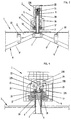
- Fig. 1 shows schematically a cross-section of a handling device obtained according to the principles of the invention, in the first coupling position for lifting the container;
- Fig. 2 shows schematically a cross-section of a handling device obtained according to the principles of the invention, in the second coupling position for emptying the container;
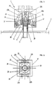
- Fig. 3 shows schematically a partial cross-section in an oversized scale of the handling device in the second coupling position of Fig. 2, according to the invention;
- Fig. 4 shows schematically a partial cross-section in an oversized scale of the device in the first coupling position of the container for said device of Fig. 1, according to the invention;
- Fig. 5 shows schematically a partial cross-section in an oversized scale of the device in a releasing/coupling position of the container for said device, according to the invention;
- Fig. 6 shows schematically a side cross-section of the device according to the invention;
- Fig. 7 and 8 shows schematically a cross-section of a variant embodiment of the coupling device, in closing and opening position respectively of the lower part of the container, according to the invention;
- Fig. 9 and 10 shows schematically a cross-section of a second variant embodiment of the coupling device, in closing and opening position respectively of the lower part of the container, according to the invention;
- Fig. 11 and 12 shows schematically a cross-section of a third variant embodiment of the coupling device, in closing and opening position respectively of the lower part of the container, according to the invention;
- Fig. 1-4 show schematically a cross-section of a handling device and a container for said device, in the first coupling position for lifting the container and in the second coupling position for emptying the container, a partial cross-section in an oversized scale of the device in the first and second coupling position of the container for said device, where
number 1 indicates the coupling device andnumber 2 indicates a container resting on the ground and fit for working together with thedevice 1. - The
container 2 presents in the middle of its upper part acylindrical bushing 3 with one end fixed securely to the container and to the other end is fixed aring 4. Thering 4 presents the lower surface flat and the upper surface in a truncated cone shape; thering 4 presents also a greater diameter than thecylindrical bushing 3 in order to obtain a coupling step with the bushing itself. -
Number 5 indicates a tubular rod passing and sliding inside thebushing 3; on the upper end of the rod 5 apin 6 is hammered; thepin 6 presents a round head shaped protruding from therod 5 and whose diameter is essentially the same as that of the rod. - The lower end of the
rod 5, which is inside thecontainer 2, presents a securely connectedbracket 7, whose ends are articulated with two levers indicated with 8 and 9 respectively. - Each
lever plate 11 fixed on the internal part of the upper wall of thecontainer 2, in such a way as to execute an angular movement around their articulation axis. - Each
levers - The end of each 8" and 9" straight part is articulated with a pair of tie rods indicated with 12, 12A and 13, 13A respectively, which are articulated with one of the two
doors container 2; Fig. 1 and 2 show only thetie rods door 14, because the tie rods 12A and 13A and thedoor 15 are placed symmetrically to thetie rods door 14 in the part of thecontainer 2 not visible in its cross-section represented in Fig. 1 and 2 (see Fig. 12 as an example). - The point of articulation of the
levers bracket 10 is such that a downward or upward movement of thelevers bracket 7, through thetubular rod 5, corresponds to an opposite movement having a greater amplitude than the ends of thestraight parts 8" and 9"; the difference between the width of the movement of thetubular rod 5 and that of the ends of thestraight parts 8" and 9" is given by the ratio existing between the point of articulation to thebracket 10 of thelevers - In other words, if the distance between the point of articulation of the
levers relative bracket 10 and their point of articulation withbracket 7 is half of the distance between the point of articulation of thelevers corresponding tie rods bracket 7 corresponds to twice the upward or downward movement of the tie rods. - Therefore, by changing the ratio between the length of the sections of the
levers bracket 10, the amplitude of the tie rod movement may be changed. - In this way a smaller vertical movement of the
tubular rod 5 with respect to the vertical movement of thetie rods container 2; therefore this movement reduction allows to reduce the length of thetubular rod 5. - The
container 2 presents also an opening, not shown, placed usually in the upper part, for inserting waste inside the container, which can differ in shape, for example round for containers for bottles, tins and similar, or rectangular or square, with or without lid. - The
coupling device 1 presents abody 16, to the lower part ofbody 16 are pivoted of thelevers 17 that present asmall tooth 18 for coupling thering 4 of thecontainer 2 for its displacement for dumping. - The lower surface of the
body 16 presents a complementary shape to thering 4 on which it is coupled during the coupling phase of thecontainer 2 as described later. - A
tubular element 19, whose end is fixed to ahydraulic actuator 20, is present inside thebody 16. The other end of thehydraulic actuator 20 is fixed to the upper part of thebody 16. - A
piston 21 is fixed torod 20A of thehydraulic actuator 20, the external diameter of this piston is substantially equal to the internal diameter of thetubular element 19 and within which it can slide under the action of thehydraulic actuator 20. - The lower base of the
piston 21 presents a shape complementary to that of the end ofpin 6 with which it is coupled. - The
levers 17 present, with views from the top according to Fig. 6, substantially a "C" shape, and they are mounted symmetrically between them with the upper and lower portions of "C", indicated with 17A and 17B respectively, which face each other and couple sideways to thebody 16. - A
mechanical actuator 22 is placed vertically between the twoportions levers 17 facing each other; thismechanical actuator 22 presents twobases cylindrical pin 24 having a diameter smaller than the two bases. Thelower base 23B of themechanical actuator 22 is fixed to the rod of a secondhydraulic actuator 25. - Between the two
bases mechanical actuator 22 is inserted a section of the end of theportion 17A of alever 17 and of theportion 17B of theother lever 17, divided between them by thecylindrical pin 24. - The movement deriving from the second
hydraulic actuator 25 works it, by means of themechanical actuator 22, so that thelevers 17 make an angular movement passing from a first position (Fig. 4) to a second position (Fig. 5) in which thesmall teeth 18 are coupled and released from thering 4 ofcontainer 2 respectively. - With the
levers 17 in the first position it is possible to lift thecontainer 2 in order to place it above the vehicle and its support for emptying the contents. - With the levers in the second position it is possible to release and/or couple the
container 2 to thecoupling device 1, at the end and/or at the beginning of the handling and emptying operations of the container respectively. - The coupling of the
container 2 and the corresponding opening for emptying occurs in the following way. - The
coupling device 1 is inserted centrally on thecontainer 2 so that the lower part of thebody 16 couples with the upper part of thering 4, which, as said previously, has a complementary shape. - The second
hydraulic actuator 25 is activated: this actuator, by means of themechanical actuator 22, rotates thelevers 17 in such a way that the relativesmall tooth 18 moves up under the edge ofring 4. Thehydraulic actuator 20 is activated in such a way that thepiston 21 rests on the head of thepin 6, and at the same time moves thebody 16 upwards in such a way as to eliminate the clearance existing between thesmall teeth 18 and the edge ofring 4, a necessary clearance to place thesmall teeth 18 under the edge of thering 4 in the phase of coupling. - The container, coupled to the edge of the
ring 4 by means of thesmall teeth 18 of thelevers 17, can be lifted by means of thedevice 1 and placed above the vehicle for emptying its contents. - The positioning of the
piston 21 on the head of thepin 6 works it so that when lifting thecontainer 2 thelower doors tie rods lower doors bar 5 given bylevers actuator 20 that through thepiston 21 presses on the head of thepin 6. - Therefore it is not necessary to move the
bar 5 to put the tie rods in traction and keep closed the bottom of the container during its handling, as in the known art. - For emptying the
container 2, when it is placed above the vehicle, it is just need to disable theactuator 20 in such a way that the slidingbar 5, not countered any more by the strength exercised by thepiston 21, can slide upwards under the thrust exercised by thelevers tie rods doors - After emptying the container, the reverse must be carried out: activate the
actuator 20 so that the slidingbar 5, under the thrust of thepiston 21, returns in thecontainer 2 and by means of thelevers doors doors - The
hydraulic actuator 20 is disarmed in such a way that thebody 16 can lower and release thesmall teeth 18, and at the same time the secondhydraulic actuator 25 is activated: the latter, by means of themechanical actuator 22 rotates thelevers 17 in such a way that the correspondingsmall tooth 18 is released from the edge of thering 4. Now, thecoupling device 1 can lift from the container and place the articulated arm to which the coupling device is connected, at rest on the vehicle in order to empty the next container. - All the operation of positioning the vehicle with respect to the container, coupling, shifting and emptying the container, occurs automatically by means of a computerised system mounted inside the cab of the vehicle.
- This system detects the positioning parameters of the vehicle in the direction with respect to the container, the distance between the vehicle and the container and the positioning of the coupling device in the container.
- The driver, after placing the vehicle near the container, with respect to the direction, must simply start the computerised system and the operation is carried out automatically.
- The positioning of the vehicle with respect to the container to be emptied, in the direction of the vehicle, occurs by means of a miniaturised camera placed on the vehicle.
- The said camera is used to transmit to a monitor placed inside the cab and therefore to the driver, the picture of a reference sign placed on the container; when this sign lines up with that of the camera, the vehicle is in the best position for executing the loading and emptying.
- For what concerns the detection of the distance of the container from the vehicle, it is obtained by means of ultrasound sensors, in such a way that the computerised system can establish how much to extend the articulated arm so that the vertical axis of the
coupling device 1 is on the vertical axis of the container. - A proximity sensor is used for detecting how much to lower the articulated arm, and consequently the
coupling device 1, in order to have the position for coupling the container. - The computerised system is not described since it is known.
- As deduced from the description, the device for coupling, emptying the contents and releasing the container is obtained in a simple and fast way.
- The characteristics of the device for handling and emptying the contents of containers for waste collection, in particular for differentiated refuse collection, and a container for said device, are clear from the description made and from the annexed drawings.
- From the above description are also clear the advantages of the device for handling and emptying the contents of containers for waste collection, in particular for differentiated refuse collection, and a container for said device, according to the present invention.
- In particular they consist in the fact that:
- the device is obtained easily and economical,
- the device presents a reduced number of mechanical components
- the device presents a reduced number of hydraulic actuators,
- the device requires a reduced number of operations for coupling and/or releasing and emptying a container,
- the device does not require coupling means for closing the bottom of the container when lifting,
- the device allows the opening and/or closing the bottom of the container with movements smaller in size with respect to those executed by the bottom of the container.
- It is obvious that many changes and applications are possible for the man skilled in the art to the device for handling and emptying containers for waste collection, in particular for differentiated refuse collection, described as an example.
- For example, the opening and/or closing of the bottom of the container can be realised with other means, for example as shown in the Fig. 7 to 12.
- The figures do not show the coupling device since it is not different from the one described before, from the operational point of view and as it is manufacture.
- The description will use the same references for the details equal to the solution described previously.
- With reference to the Fig. 7 and 8, which shows schematically a cross-section of a variant of the coupling device for a waste container, in closing and opening position respectively of the lower part of the container,
number 2A indicates a container. - The
container 2A presents in the middle of its upper part thecylindrical bushing 3 with one end fixed securely to the container and to the other end is fixed thering 4. - Number 5' indicates a tubular rod passing and sliding inside the
bushing 3; on the upper end of the rod 5' there is hammered thepin 6 described previously. - To the lower end of rod 5', which is placed inside the
container 2A, is connected afirst pulley 27, with 28 is indicated a second pulley fixed to the inner upper wall of thecontainer 2A by means of known type brackets, which presents an orientation rotated by 180° with respect to thefirst pulley 27. -
Number 29 indicates a cylindrical envelope closed at one end and fixed with the other end to the inner upper wall of thecontainer 2A. -
Number 30 indicates a rope that is fixed at one end to the inner upper wall of thecontainer 2A, while the other end is fixed to atubular element 31. Therope 30, before being fixed to thetubular element 31, passes around thefirst pulley 27 and then around thesecond pulley 28. - To the other end of the
tubular element 31 are articulated of the tie rods 12' and 13'; each tie rods is articulated with one of the twodoors container 2A. - The
tubular element 31 can slide within acylindrical bushing 32 present inside theenvelope 29 to which is fixed vertically to its lower wall. Thecylindrical bushing 32 has the function to guide thetubular element 31. - The vertical downward movement of the tubular rod 5' works it so that the
pulley 27, connected to it, makes the same movement; the movement of thepulley 27 pushes downwards therope 30, which, by means of thepulley 28 fixed to the container, drives upward thetubular element 31. The upward movement of thetubular element 31, to which are connected the tie rods 12' and 13', determine the closing of thedoors - It is implicit that an opposite movement of the tubular rod 5' determines the opening of the
doors - The coupling, lifting and emptying of the
container 2A occurs as described above, i.e. with thedevice 1 placed on thecontainer 2A to which it is coupled by means of thesmall teeth 18 of thelevers 17. - The
piston 21, controlled by thehydraulic actuator 20, is placed on thepin 6 of the tubular rod 5', which is kept locked in thecontainer 2A. In this position thepulley 27 connected to the tubular rod 5', is placed downwards in such a way as to push therope 30 downwards, which, by means of thepulley 28 drives thetubular element 31 upwards. This upward movement of thetubular element 31, to which are connected the tie rods 12' and 13', determines and keeps thedoors - When the
container 2A is positioned on the vehicle for emptying its contents, thehydraulic actuator 20 is disabled in such a way that the sliding rod 5', not opposed any more by the force exerted by thepiston 21, can slide upwards under the thrust exerted by therope 30 on thepulley 27, by means of thepulley 28, ensuing the downward movement of thetubular element 31 given by the tie rods 12' and 13' after the opening of thedoors container 2A. - Also in this variant the amplitude of the movement of the tubular element is twice the amplitude of the movement of the rod 5'; this difference derives, as known, from the system of transmission of the movement by means of two pulleys of which one is fixed.
- With reference to Fig. 9 and 10, which shows schematically a cross-section of a second variant of the coupling device of a waste container, in closing position and in opening position of the lower part of the container, respectively, according to the invention, 2B indicates a waste container of the type embedded in the ground.
-
Number 33 indicates a protruding part of thecontainer 2B, which is internally divided in two parts indicated with 34 and 35, respectively. Thepart 34 presents anopening 36 for inserting the waste in thecontainer 2B. - The part 35 presents externally the
cylindrical bushing 3, with one end fixed securely to the protrudingpart 33 of the container, while to the other end is fixed thering 4. - The same pulley device, represented and described with reference to Fig. 7 and 8, is present inside the part 35.
- It goes without saying that some differences in the dimensions of some details may occur between the two devices due to the different positioning of the container, without affecting the operation.
- With reference to the Fig. 11 and 12, which shows schematically a cross-section of a third variant of the coupling device of a waste container, in closing and opening position respectively of the lower part of the container, according to the invention, number 2C indicates a waste container.
- The container 2C presents in the middle of its upper part the
cylindrical bushing 3 with one end fixed securely to the container, while to the other end is fixed thering 4. -
Number 5" indicates a tubular rod passing and sliding inside thebushing 3; on the upper end of therod 5" is hammered thepin 6. - The lower part of the
rod 5", which is inside the container 2C, presents a section with two series of transversal openings 37 placed symmetrically opposed. -
Number 38 indicates two brackets presenting a horizontal section fixed securely to the internal part of the upper wall of container 2C, and a vertical section protruding inside the container. The vertical sections of the twobrackets 38 are parallel in such a way as to allow the passage of the slidingbar 5" and the housing of two equal levers indicated with 39. - The
levers 39 present a profile with a substantially semi-cylindrical portion 39' connected to astraight portion 39". Thelevers 39 are pivoted between thebrackets 38 in the geometric point of the generatrix of the semi-cylindrical portion 39'. The semi-cylindrical portion 39' presents on the edge a toothing 40 that enters in the openings 37 of thetubular rod 5". - The end of the
straight part 39" of eachlever 39 is articulated a couple of equal tie rods indicated with 12', 12'A and 13', 13'A respectively, which are articulated with one of the twodoors - The point of articulation of the
levers 39 to thebrackets 38 is such that a downward or upward movement of thelevers 39 by means of thetubular rod 5" to which they are connected by the toothing 40, corresponds to the same movement of the ends of thestraight parts 39" having a greater amplitude equal to the ratio existing between the point of articulation to thebrackets 38 of thelevers 39 and their ends, as previously described. - In other words, if the distance between the point of articulation of the
levers 39 to thebrackets 38 and their point of articulation with thetubular rod 5" is half of the distance between the point of articulation of thelevers 39 to the tie rods 12' and 13', an upward or downward movement of thetubular rod 5" corresponds to the upward or downward double movement of the tie rods. - In this way a smaller vertical movement of the
tubular rod 5" as to the vertical movement of the tie rods 12', 12'A, 13' and 13'A is enough to open and/or close the lower doors of container 2C; therefore this movement reduction allows to reduce the length of thetubular rod 5". - It is obvious that many other changes and applications are possible for the man skilled in the art to the device for handling and emptying containers for waste collection, in particular for differentiated refuse collection, described as an example, without departing from the scope of the present invention, as defined in the appended claims.
Claims (42)
- Device for handling and emptying the contents of containers for waste collection, in particular for differentiated refuse collection, comprisingcharacterised in thata coupling device (1) for connection to a waste container (2;2A;2B;2C);a waste container (2;2A;2B;2C) presenting at least one door (14;15) and adapted to be handled by the said coupling device (1)
where said coupling device (1) presents a body (16) comprising first coupling means (17,18,22,24,25) for coupled engagement with said container (2;2A;2B;2C),
and where said container (2;2A;2B;2C) presents second means (3,4) adapted to be engaged by and coupled to said coupling device (1), third means (5;5';5") slidably arranged in said second means (3,4) and fourth means (7,8,9,10,12,12A,13,13A,12',12'A,13',13'A; 27,28,30,31;38,39) connected at one end to said at least one door (14;15) and at the other end to said third means (5;5';5") whereby actuation of said third means (5;5';5") causes opening and/or closing of the at least one door (14,15) of said container (2;2A;2B;2C)said coupling device (1) comprises fifth means (19,20,21) slidably arranged in said body (16) for actuation and for control of the vertical movement of said third means (5;5';5") of said container (2;2A;2B;2C),said fourth means (7,8,9,10,12,12A,13,13A,12',12'A,13',13'A; 27,28,30,31;38,39) are constructed in such a way that the displacement of its at least one end connected to the at least one door (14;15) is amplified relatively to the displacement of said third means (5;5';5"). - Device, according to claim 1, characterised in that said first coupling means (17,18,22,24,25) comprise at least one lever (17) capable of angular movement for passing from a first rest position to a second working position for the coupling of said first coupling means (17,18,22,24,25) to said second means (3,4).
- Device, according to claims 1 and 2, characterised in that said first coupling means (17,18,22,24,25) comprise at least one mechanical actuator (22) capable of passing from the said first to the said second position of said lever (17) and vice versa.
- Device, according to claims 1 and 3, characterised in that said first coupling means (17,18,22,24,25) comprise at least a first hydraulic actuator (25) capable of starting of said mechanical actuator (22).
- Device, according to claims 1 and 2, characterised in that said first coupling means (17,18,22,24,25) comprise at least a small coupling tooth (18) capable of connecting with said second means (3,4).
- Device, according to claim 1, characterised in that said second means (3,4) comprise at least a bushing (3), in particular said bushing (3) is securely fixed to the upper part of said container (2;2A;2B;2C).
- Device, according to claims 1 and 6, characterised in that said second means (3,4) comprise a ring (4), in particular said ring (4) is securely fixed to said bushing (3) and capable of coupling with said small coupling tooth (18) for handling said container (2;2A;2B;2C).
- Device, according to claims 1 and 6, characterised in that said third means (5;5';5") comprise at least a rod (5;5';5"), in particular said rod (5;5';5") being slides in said bushing (3).
- Device, according to claim 8, characterised in that said rod (5;5';5") presents a first end closed by a pin (6), in particular said pin (6) presents a round-shaped head protruding from said rod (5;5';5") and with a diameter substantially equal to the diameter of said rod.
- Device, according to claim 1, characterised in that said fifth means (19,20,21) comprise a second hydraulic actuator (20) connected to said body (16) apt to realise a lock of a vertical movement of said rod (5;5';5").
- Device, according to the previous claim, characterised in that said hydraulic actuator is capable of producing a vertical displacement of said rod (5;5';5") for opening and/or closing of said door (14,15).
- Device, according to claim 1, characterised in that said fifth means (19,20,21) comprise a piston (21) connected to said second hydraulic actuator (20).
- Device, according to claim 1, characterised in that said fifth means (19,20,21) comprise a tubular element (19) in which slides said piston (21).
- Device, according to at least one of the previous claims, characterised in that a surface of said piston (21) presents a complementary shape of the head of said pin (6) for their joint coupling.
- Device, according to claims 1 and 8, characterised in that said fourth means (7,8,9,10,12,12A,13,13A,12',12'A,13',13'A; 27,28,30, 31;38,39) comprise at least a first bracket (7), in particular said first bracket (7) is integral to said rod (5;5';5").
- Device, according to claim 1, characterized in that said fourth means (7,8,9,10,12,12A,13,13A,12',12'A,13',13'A; 27,28,30,31; 38,39) comprise at least two levers (8,9;39).
- Device, according to claim 1, characterised in that said fourth means (7,8,9,10,12,12A,13,13A,12',12'A,13',13'A; 27,28,30, 31;38,39) comprise at least a second bracket (10), in particular said second bracket (10) is articulated with a third bracket (11) integral to said container (2;2A;2B;2C).
- Device, according to the previous claim, characterised in that said second bracket (10) is angularly movable around the articulation axis to said third bracket (11).
- Device, according to at least one of the previous claims, characterised in that a first end of said levers (8,9;39) is articulated with said first bracket (7).
- Device, according to at least one of the previous claims, characterised in that said levers (8,9;39) present two straight parts (8,8';9,9') inclined one with respect to the other.
- Device, according to at least one of the previous claims, characterised in that at least one of said straight parts (8,8';9,9') is articulated with said second bracket (10).
- Device, according to claim 1, characterised in that said fourth means (7,8,9,10,12,12A,13,13A,12',12'A,13',13'A;27,28,30,31;38,39) comprise at least one tie rod (12,12A,13,13A,12',12'A,13',13'A) which is articulated with a first end to said door (14,15) of said container (2;2A;2B;2C).
- Device, according to the previous claim, characterised in that a second end of said tie rod (12,12A,13,13A,12',12'A,13',13'A) is articulated with a second end of said levers (8,9;39).
- Device, according to one or more of the previous claims, characterised in that said levers (8,9;39) are capable of transmitting the movement of said rod (5;5';5") to said tie rod (12,12A,13,13A, 12',12'A,13',13'A) for opening and/or closing of said door (14,15).
- Device, according to claim 1, characterised in that said fourth means (7,8,9,10,12,12A,13,13A,12',12'A,13',13'A;27,28,30,31;38,39) comprise at least a first pulley (27) connected to said rod (5;5';5").
- Device, according to claim 1, characterised in that said fourth means (7,8,9,10,12,12A,13,13A,12',12'A,13',13'A;27,28,30,31;38,39) comprise at least a second pulley (28) connected to said container (2;2A,2B;2C).
- Device, according to claim 1, characterised in that said fourth means (7,8,9,10,12,12A,13,13A,12',12'A,13',13'A;27,28,30,31;38,39) comprise at least a rope (30) connected to said first (27) and said second pulley (28).
- Device, according to claim 1, characterised in that said fourth means (7,8,9,10,12,12A,13,13A,12',12'A,13',13'A;27,28,30,31;38,39) comprise at least a tubular element (31).
- Device, according to claim 27, characterised in that an end of said rope (30) is fixed to the inner upper wall of said container (2;2A;2B;2C).
- Device, according to claims 27 and 28, characterised in that a second end of said rope (30) is fixed to a first end of said tubular element (31).
- Device, according to one or more of the previous claims, characterised in that a second end of said tie rod (12,12A,13,13A,12',12'A,13',13'A) is articulated to a second end of said tubular element (31).
- Device, according to one or more of the previous claims, characterised in that said first (27) and said second pulley (28) are capable of transmitting the movement of said rod (5;5';5") to said tie rod (12,12A,13,13A, 12',12'A,13',13'A) for opening and/or closing of said door (14,15).
- Device, according to claim 8, characterised in that the lower part of said rod (5;5';5") presents two series of transversal openings (37) placed symmetrically opposed to each other.
- Device, according to claim 1, characterised in that said fourth means (7,8,9,10,12,12A,13,13A,12',12'A,13',13'A;27,28,30,31;38,39) comprise at least a third bracket (38), in particular said third bracket (38) is integral with the inner upper wall of said container (2;2A;2B;2C).
- Device, according to at least one of the previous claims, characterised in that said levers (8,9;39) present a profile having a substantially semi-cylindrical portion (39') connected to a straight portion (39").
- Device, according to at least one of the previous claims, characterised in that said levers (8,9;39) are articulated to said third bracket (38), in particular in the geometric point of the generatrix of said semi-cylindrical portion (39').
- Device, according to at least one of the previous claims, characterised in that said semi-cylindrical portion (39') presents on the edge a toothing (40) capable of entering in said openings (37) of said rod (5;5';5").
- Device, according to one or more of the previous claims, characterised in that the amplitude of the vertical movement of said tie rod (12,12A,13,13A,12',12'A,13',13'A) is greater than the amplitude of the movement of said rod (5;5';5").
- Device, according to one or more of the previous claims, characterised in that a downward and/or upward movement of said rod (5;5';5") corresponds to a greater opposite movement of said tie rod (12,12A,13,13A,12',12'A,13',13'A) for opening and/or closing of said door (14,15).
- Device, according to one or more previous claims, characterized in that said fifth means (19,20,21) are capable of locking and/or allowing the movement of said third means (5;5';5").
- Method for handling and emptying the contents of containers for waste collection, in particular for differentiated refuse collection using a device according to one or more previous claims.
- Method for handling and emptying the contents of containers for waste collection, in particular for differentiated refuse collection, comprising the following steps:characterised by the following steps:to activate a coupling device (1) for its connection to a waste container (2;2A;2B;2C) presenting at least one door (14;15) and adapted to be handled by said coupling device (1), where said coupling device (1) presents a body (16) comprising first coupling means (17,18,22,24,25);to activate said first coupling means (17,18,22,24,25) for a coupled engagement with said container (2;2A;2B;2C), which additionally presents second means (3,4) adapted to be engaged by and coupled to said coupling device (1), to provide third means (5;5';5") slidably arranged in said second means (3,4) and fourth means (7,8,9,10,12,12A,13,13A,12',12'A,13',13'A;27,28,30,31;38,39) connected at one end to said at least one door (14;15) and at the other end to said third means (5;5';5");to activate said third means (5;5';5") in order to cause the opening and/or closing of the at least one door (14,15) of said container (2;2A;2B;2C),to provide fifth means (19,20,21) of said coupling device (1), slidably arranged in said body (16), which actuate and control the vertical movement of said third means (5;5';5") of said container (2;2A;2B;2C),to activate said fifth means in order to obtain an amplified displacement of said third means (5;5';5") through said fourth means (7,8,9,10,12,12A,13,13A,12',12'A,13',13'A;27,28,30,31;38,39) which are constructed in such a way that the displacement of its at least one end connected to the at least one door (14;15) is amplified relative to the displacement of said third means.
Applications Claiming Priority (2)
| Application Number | Priority Date | Filing Date | Title |
|---|---|---|---|
| IT2000TO000679A IT1320227B1 (en) | 2000-07-05 | 2000-07-05 | DEVICE FOR HANDLING, AND DISCHARGE OF CONTENT, CONTAINERS USED FOR WASTE COLLECTION, AND CONTAINERS FOR SAID |
| ITTO000679 | 2000-07-05 |
Publications (2)
| Publication Number | Publication Date |
|---|---|
| EP1172308A1 EP1172308A1 (en) | 2002-01-16 |
| EP1172308B1 true EP1172308B1 (en) | 2004-09-22 |
Family
ID=11457897
Family Applications (1)
| Application Number | Title | Priority Date | Filing Date |
|---|---|---|---|
| EP01116183A Expired - Lifetime EP1172308B1 (en) | 2000-07-05 | 2001-07-04 | Device and method for handling and emptying containers destined for the waste collection |
Country Status (5)
| Country | Link |
|---|---|
| EP (1) | EP1172308B1 (en) |
| AT (1) | ATE276941T1 (en) |
| DE (1) | DE60105710T2 (en) |
| ES (1) | ES2228704T3 (en) |
| IT (1) | IT1320227B1 (en) |
Cited By (5)
| Publication number | Priority date | Publication date | Assignee | Title |
|---|---|---|---|---|
| EP3115317A1 (en) | 2015-07-07 | 2017-01-11 | Palvi, S.L. | Method and device for handling and emptying waste containers |
| IT201900020346A1 (en) | 2019-11-05 | 2021-05-05 | Nord Eng S R L | CONTAINER FOR THE COLLECTION OF WASTE, IN PARTICULAR FOR THE SEPARATE COLLECTION |
| IT202200015417A1 (en) | 2022-07-21 | 2024-01-21 | Nord Eng S P A | WASTE COLLECTION SYSTEM, IN PARTICULAR FOR SEPARATE COLLECTION, AND RELATED METHOD |
| IT202300009900A1 (en) | 2023-05-16 | 2024-11-16 | Alia Servizi Ambientali S P A | CONTAINER FOR THE DISPOSAL OF WASTE, IN PARTICULAR FOR AUTHENTICATED DISPOSAL |
| EP4606732A1 (en) | 2024-02-20 | 2025-08-27 | ESE World B.V. | Waste container |
Families Citing this family (13)
| Publication number | Priority date | Publication date | Assignee | Title |
|---|---|---|---|---|
| CH697438B1 (en) * | 2004-12-14 | 2008-10-15 | Stefano Mondini | Waste container with a multiplier device between the bottom and the coupling member. |
| NL1032732C2 (en) * | 2006-10-24 | 2008-04-25 | Harm Bakker | Container gripper with operating means for a release mechanism and telescopic piston / cylinder combination to be used therein. |
| ES2371957B1 (en) * | 2009-08-20 | 2012-11-19 | Mecamesor, S.A. | HITCH SYSTEM AND ITS USE FOR THE ELEVATION AND OPENING OF CONTAINERS. |
| ES2372037B1 (en) * | 2009-12-21 | 2012-12-19 | Ros Roca S.A. | SYSTEM FOR THE HANDLING OF WASTE COLLECTION CONTAINERS. |
| ES2362848B1 (en) * | 2011-04-04 | 2012-07-24 | Ricardo Romero Martí | HITCH HEAD AND OPEN / CLOSE SYSTEM FOR DOORS OF A CONDUCABLE CONTAINER WITH SUCH HITCH HEAD. |
| ES2397999B1 (en) * | 2011-04-29 | 2014-01-16 | Mecamesor, S.A. | HITCHING SYSTEM AND ITS USE FOR THE LIFTING AND OPENING OF CONTAINERS. |
| CH705076A2 (en) * | 2011-06-09 | 2012-12-14 | Villiger Public Systems Gmbh | Coupling device for a lifting tool. |
| ES2545827B1 (en) * | 2014-03-14 | 2016-06-22 | Explin Iris, S.L. | System and method of opening and closing container gates |
| ES2661689T3 (en) | 2015-07-08 | 2018-04-03 | Palvi, S.L. | Waste container with lower gate opening mechanism |
| IT201600096108A1 (en) * | 2016-09-26 | 2018-03-26 | Nord Eng S R L | SYSTEM FOR THE COLLECTION OF WASTE, IN PARTICULAR FOR THE DIFFERENTIATED COLLECTION, AND RELATIVE METHOD |
| ES2975687T3 (en) | 2021-07-05 | 2024-07-11 | Palvi S L | Procedure and device for handling waste collection containers |
| EP4129861B1 (en) | 2021-08-05 | 2024-01-17 | Palvi, S.L. | Method and device for handling waste collection containers |
| EP4238892A1 (en) * | 2022-03-01 | 2023-09-06 | Ballester Rebolloso, Fernando | Coupler for container anchors |
Family Cites Families (5)
| Publication number | Priority date | Publication date | Assignee | Title |
|---|---|---|---|---|
| DE3915580A1 (en) | 1989-05-12 | 1990-11-15 | Kinshofer Greiftechnik | CONTAINER WITH HANDLING DEVICE |
| FR2704538A1 (en) * | 1993-04-26 | 1994-11-04 | Polz Sarl | Device for grasping containers |
| DE9416727U1 (en) * | 1994-10-18 | 1996-02-22 | Peters, Klaus-Tilmann, Dipl.-Ing., 41334 Nettetal | Disposal container |
| DE29519378U1 (en) * | 1995-12-07 | 1997-05-15 | Premonex Consulting Ltd., Orpington, Kent | Collection container for recyclables |
| DE29906988U1 (en) * | 1999-04-09 | 1999-09-09 | Paul Wolff GmbH & Co KG, 41068 Mönchengladbach | Storage device for depot containers |
-
2000
- 2000-07-05 IT IT2000TO000679A patent/IT1320227B1/en active
-
2001
- 2001-07-04 DE DE60105710T patent/DE60105710T2/en not_active Expired - Lifetime
- 2001-07-04 AT AT01116183T patent/ATE276941T1/en not_active IP Right Cessation
- 2001-07-04 EP EP01116183A patent/EP1172308B1/en not_active Expired - Lifetime
- 2001-07-04 ES ES01116183T patent/ES2228704T3/en not_active Expired - Lifetime
Cited By (8)
| Publication number | Priority date | Publication date | Assignee | Title |
|---|---|---|---|---|
| EP3115317A1 (en) | 2015-07-07 | 2017-01-11 | Palvi, S.L. | Method and device for handling and emptying waste containers |
| WO2017006163A1 (en) | 2015-07-07 | 2017-01-12 | Palvi, Sl | Method and device for handling and emptying waste collection containers |
| IT201900020346A1 (en) | 2019-11-05 | 2021-05-05 | Nord Eng S R L | CONTAINER FOR THE COLLECTION OF WASTE, IN PARTICULAR FOR THE SEPARATE COLLECTION |
| US12479655B2 (en) | 2019-11-05 | 2025-11-25 | Nord Engineering S.P.A. | Container for waste collection |
| IT202200015417A1 (en) | 2022-07-21 | 2024-01-21 | Nord Eng S P A | WASTE COLLECTION SYSTEM, IN PARTICULAR FOR SEPARATE COLLECTION, AND RELATED METHOD |
| EP4558422A1 (en) | 2022-07-21 | 2025-05-28 | Nord Engineering S.p.A. | System for waste collection, in particular for differentiated waste collection, and method thereof |
| IT202300009900A1 (en) | 2023-05-16 | 2024-11-16 | Alia Servizi Ambientali S P A | CONTAINER FOR THE DISPOSAL OF WASTE, IN PARTICULAR FOR AUTHENTICATED DISPOSAL |
| EP4606732A1 (en) | 2024-02-20 | 2025-08-27 | ESE World B.V. | Waste container |
Also Published As
| Publication number | Publication date |
|---|---|
| DE60105710T2 (en) | 2005-09-08 |
| IT1320227B1 (en) | 2003-11-26 |
| ITTO20000679A0 (en) | 2000-07-05 |
| ATE276941T1 (en) | 2004-10-15 |
| ITTO20000679A1 (en) | 2002-01-05 |
| ES2228704T3 (en) | 2005-04-16 |
| DE60105710D1 (en) | 2004-10-28 |
| EP1172308A1 (en) | 2002-01-16 |
Similar Documents
| Publication | Publication Date | Title |
|---|---|---|
| EP1172308A1 (en) | Device and method for handling and emptying containers destined for the waste collection | |
| US6276888B1 (en) | Reception, containing and compacting system of solid wastes | |
| EP1084069B1 (en) | Device for handling waste collection containers | |
| EP2233426B1 (en) | Locking mechanism related to a container. | |
| US5516135A (en) | Tag axle latching mechanism | |
| US5014870A (en) | Container with a handling device | |
| EP1916218B1 (en) | Container gripper having operating means for a discharge mechanism of the container | |
| WO1996000690A1 (en) | Box pallet | |
| EP1389591B1 (en) | Device for handling and emptying waste collection containers | |
| US5938393A (en) | Container vehicle with loading means | |
| GB2188302A (en) | Container emptying mechanisms | |
| US5006030A (en) | Apparatus for transferring refuse from containers into refuse equipment | |
| NL194120C (en) | Lifting frame for lifting containers. | |
| EP1142803B1 (en) | Device for handling and emptying the contents of containers destined for the waste collection | |
| EP3115318B1 (en) | Waste container with an opening mechanism of lower gates | |
| CA2196412A1 (en) | Collection system for materials destined for recycling | |
| US20240253897A1 (en) | Door release mechanism for a container system | |
| US4998640A (en) | Parallelepipedic container | |
| DE102006014731A1 (en) | Fork-lift truck for use in glass industry, has pivoting bolts arranged at common center line, which runs through pivoting point of container loaded with its nominal volume, and retainer formed at end of supporting arm complementary to bolts | |
| WO2015095914A1 (en) | Side discharge tipper door linkage | |
| EP2233354A1 (en) | Column for the tilting back side of vehicle's dump bodies | |
| US12612249B2 (en) | Mechanical arm | |
| EP0760347A1 (en) | Closing mechanism for a pivoting container door | |
| ITMI950248A1 (en) | DEVICE FOR HANDLING GOODS OF THE TAKE-OFF TYPE WITH AUTOMATIC GRIPPING SHEET | |
| FR2733213A1 (en) | Bottom-discharge container for collection of refuse etc. |
Legal Events
| Date | Code | Title | Description |
|---|---|---|---|
| PUAI | Public reference made under article 153(3) epc to a published international application that has entered the european phase |
Free format text: ORIGINAL CODE: 0009012 |
|
| AK | Designated contracting states |
Kind code of ref document: A1 Designated state(s): AT BE CH CY DE DK ES FI FR GB GR IE IT LI LU MC NL PT SE TR |
|
| AX | Request for extension of the european patent |
Free format text: AL;LT;LV;MK;RO;SI |
|
| 17P | Request for examination filed |
Effective date: 20020628 |
|
| AKX | Designation fees paid |
Free format text: AT BE CH CY DE DK ES FI FR GB GR IE IT LI LU MC NL PT SE TR |
|
| 17Q | First examination report despatched |
Effective date: 20021025 |
|
| GRAP | Despatch of communication of intention to grant a patent |
Free format text: ORIGINAL CODE: EPIDOSNIGR1 |
|
| GRAS | Grant fee paid |
Free format text: ORIGINAL CODE: EPIDOSNIGR3 |
|
| GRAA | (expected) grant |
Free format text: ORIGINAL CODE: 0009210 |
|
| AK | Designated contracting states |
Kind code of ref document: B1 Designated state(s): AT BE CH CY DE DK ES FI FR GB GR IE IT LI LU MC NL PT SE TR |
|
| PG25 | Lapsed in a contracting state [announced via postgrant information from national office to epo] |
Ref country code: FI Free format text: LAPSE BECAUSE OF FAILURE TO SUBMIT A TRANSLATION OF THE DESCRIPTION OR TO PAY THE FEE WITHIN THE PRESCRIBED TIME-LIMIT Effective date: 20040922 Ref country code: BE Free format text: LAPSE BECAUSE OF FAILURE TO SUBMIT A TRANSLATION OF THE DESCRIPTION OR TO PAY THE FEE WITHIN THE PRESCRIBED TIME-LIMIT Effective date: 20040922 Ref country code: TR Free format text: LAPSE BECAUSE OF FAILURE TO SUBMIT A TRANSLATION OF THE DESCRIPTION OR TO PAY THE FEE WITHIN THE PRESCRIBED TIME-LIMIT Effective date: 20040922 Ref country code: AT Free format text: LAPSE BECAUSE OF FAILURE TO SUBMIT A TRANSLATION OF THE DESCRIPTION OR TO PAY THE FEE WITHIN THE PRESCRIBED TIME-LIMIT Effective date: 20040922 |
|
| REG | Reference to a national code |
Ref country code: GB Ref legal event code: FG4D |
|
| REG | Reference to a national code |
Ref country code: CH Ref legal event code: EP |
|
| REG | Reference to a national code |
Ref country code: IE Ref legal event code: FG4D |
|
| REF | Corresponds to: |
Ref document number: 60105710 Country of ref document: DE Date of ref document: 20041028 Kind code of ref document: P |
|
| PG25 | Lapsed in a contracting state [announced via postgrant information from national office to epo] |
Ref country code: SE Free format text: LAPSE BECAUSE OF FAILURE TO SUBMIT A TRANSLATION OF THE DESCRIPTION OR TO PAY THE FEE WITHIN THE PRESCRIBED TIME-LIMIT Effective date: 20041222 Ref country code: DK Free format text: LAPSE BECAUSE OF FAILURE TO SUBMIT A TRANSLATION OF THE DESCRIPTION OR TO PAY THE FEE WITHIN THE PRESCRIBED TIME-LIMIT Effective date: 20041222 Ref country code: GR Free format text: LAPSE BECAUSE OF FAILURE TO SUBMIT A TRANSLATION OF THE DESCRIPTION OR TO PAY THE FEE WITHIN THE PRESCRIBED TIME-LIMIT Effective date: 20041222 |
|
| REG | Reference to a national code |
Ref country code: CH Ref legal event code: NV Representative=s name: ING. CARLO GAGGINI |
|
| REG | Reference to a national code |
Ref country code: ES Ref legal event code: FG2A Ref document number: 2228704 Country of ref document: ES Kind code of ref document: T3 |
|
| PG25 | Lapsed in a contracting state [announced via postgrant information from national office to epo] |
Ref country code: IE Free format text: LAPSE BECAUSE OF NON-PAYMENT OF DUE FEES Effective date: 20050704 Ref country code: LU Free format text: LAPSE BECAUSE OF NON-PAYMENT OF DUE FEES Effective date: 20050704 Ref country code: CY Free format text: LAPSE BECAUSE OF FAILURE TO SUBMIT A TRANSLATION OF THE DESCRIPTION OR TO PAY THE FEE WITHIN THE PRESCRIBED TIME-LIMIT Effective date: 20050704 |
|
| PLBE | No opposition filed within time limit |
Free format text: ORIGINAL CODE: 0009261 |
|
| STAA | Information on the status of an ep patent application or granted ep patent |
Free format text: STATUS: NO OPPOSITION FILED WITHIN TIME LIMIT |
|
| PG25 | Lapsed in a contracting state [announced via postgrant information from national office to epo] |
Ref country code: MC Free format text: LAPSE BECAUSE OF NON-PAYMENT OF DUE FEES Effective date: 20050731 |
|
| ET | Fr: translation filed | ||
| 26N | No opposition filed |
Effective date: 20050623 |
|
| REG | Reference to a national code |
Ref country code: IE Ref legal event code: MM4A |
|
| PG25 | Lapsed in a contracting state [announced via postgrant information from national office to epo] |
Ref country code: PT Free format text: LAPSE BECAUSE OF NON-PAYMENT OF DUE FEES Effective date: 20050222 |
|
| REG | Reference to a national code |
Ref country code: FR Ref legal event code: PLFP Year of fee payment: 16 |
|
| REG | Reference to a national code |
Ref country code: FR Ref legal event code: PLFP Year of fee payment: 17 |
|
| REG | Reference to a national code |
Ref country code: FR Ref legal event code: PLFP Year of fee payment: 18 |
|
| PGFP | Annual fee paid to national office [announced via postgrant information from national office to epo] |
Ref country code: NL Payment date: 20200722 Year of fee payment: 20 |
|
| PGFP | Annual fee paid to national office [announced via postgrant information from national office to epo] |
Ref country code: DE Payment date: 20200731 Year of fee payment: 20 Ref country code: ES Payment date: 20200804 Year of fee payment: 20 Ref country code: FR Payment date: 20200717 Year of fee payment: 20 Ref country code: GB Payment date: 20200722 Year of fee payment: 20 |
|
| PGFP | Annual fee paid to national office [announced via postgrant information from national office to epo] |
Ref country code: CH Payment date: 20200725 Year of fee payment: 20 Ref country code: IT Payment date: 20200731 Year of fee payment: 20 |
|
| REG | Reference to a national code |
Ref country code: DE Ref legal event code: R071 Ref document number: 60105710 Country of ref document: DE |
|
| REG | Reference to a national code |
Ref country code: NL Ref legal event code: MK Effective date: 20210703 |
|
| REG | Reference to a national code |
Ref country code: GB Ref legal event code: PE20 Expiry date: 20210703 |
|
| REG | Reference to a national code |
Ref country code: ES Ref legal event code: FD2A Effective date: 20211013 |
|
| PG25 | Lapsed in a contracting state [announced via postgrant information from national office to epo] |
Ref country code: GB Free format text: LAPSE BECAUSE OF EXPIRATION OF PROTECTION Effective date: 20210703 |
|
| PG25 | Lapsed in a contracting state [announced via postgrant information from national office to epo] |
Ref country code: ES Free format text: LAPSE BECAUSE OF EXPIRATION OF PROTECTION Effective date: 20210705 |