EP1172200A1 - Ceiling member for automobile interior - Google Patents
Ceiling member for automobile interior Download PDFInfo
- Publication number
- EP1172200A1 EP1172200A1 EP01116866A EP01116866A EP1172200A1 EP 1172200 A1 EP1172200 A1 EP 1172200A1 EP 01116866 A EP01116866 A EP 01116866A EP 01116866 A EP01116866 A EP 01116866A EP 1172200 A1 EP1172200 A1 EP 1172200A1
- Authority
- EP
- European Patent Office
- Prior art keywords
- substrate
- ceiling member
- unventilated
- covering material
- edges
- Prior art date
- Legal status (The legal status is an assumption and is not a legal conclusion. Google has not performed a legal analysis and makes no representation as to the accuracy of the status listed.)
- Granted
Links
Images


Classifications
-
- B—PERFORMING OPERATIONS; TRANSPORTING
- B32—LAYERED PRODUCTS
- B32B—LAYERED PRODUCTS, i.e. PRODUCTS BUILT-UP OF STRATA OF FLAT OR NON-FLAT, e.g. CELLULAR OR HONEYCOMB, FORM
- B32B1/00—Layered products having a non-planar shape
-
- B—PERFORMING OPERATIONS; TRANSPORTING
- B60—VEHICLES IN GENERAL
- B60R—VEHICLES, VEHICLE FITTINGS, OR VEHICLE PARTS, NOT OTHERWISE PROVIDED FOR
- B60R13/00—Elements for body-finishing, identifying, or decorating; Arrangements or adaptations for advertising purposes
- B60R13/02—Internal Trim mouldings ; Internal Ledges; Wall liners for passenger compartments; Roof liners
- B60R13/0212—Roof or head liners
-
- G—PHYSICS
- G10—MUSICAL INSTRUMENTS; ACOUSTICS
- G10K—SOUND-PRODUCING DEVICES; METHODS OR DEVICES FOR PROTECTING AGAINST, OR FOR DAMPING, NOISE OR OTHER ACOUSTIC WAVES IN GENERAL; ACOUSTICS NOT OTHERWISE PROVIDED FOR
- G10K11/00—Methods or devices for transmitting, conducting or directing sound in general; Methods or devices for protecting against, or for damping, noise or other acoustic waves in general
- G10K11/16—Methods or devices for protecting against, or for damping, noise or other acoustic waves in general
-
- B—PERFORMING OPERATIONS; TRANSPORTING
- B60—VEHICLES IN GENERAL
- B60R—VEHICLES, VEHICLE FITTINGS, OR VEHICLE PARTS, NOT OTHERWISE PROVIDED FOR
- B60R13/00—Elements for body-finishing, identifying, or decorating; Arrangements or adaptations for advertising purposes
- B60R13/08—Insulating elements, e.g. for sound insulation
- B60R13/0815—Acoustic or thermal insulation of passenger compartments
-
- B—PERFORMING OPERATIONS; TRANSPORTING
- B60—VEHICLES IN GENERAL
- B60R—VEHICLES, VEHICLE FITTINGS, OR VEHICLE PARTS, NOT OTHERWISE PROVIDED FOR
- B60R13/00—Elements for body-finishing, identifying, or decorating; Arrangements or adaptations for advertising purposes
- B60R13/02—Internal Trim mouldings ; Internal Ledges; Wall liners for passenger compartments; Roof liners
- B60R2013/0287—Internal Trim mouldings ; Internal Ledges; Wall liners for passenger compartments; Roof liners integrating other functions or accessories
Definitions
- the present invention relates to a ceiling member for an automobile interior.
- Ceiling members for automobile interiors are known in the art.
- One example of such ceiling members is known from Japanese Utility Model Post-Exam Publication No. HEI 3-46996 entitled "VEHICLE INTERIOR MEMBER”.
- the ceiling member 100 includes a covering material 101 facing towards or exposed to a passenger compartment of an automobile, a ventilative cushioning material 102 laminated to the covering material 101, a ventilative foam 103 lying on the cushioning material 102, a resinous sheet 104 laid on the foam 103, and a lining material 105 applied to the sheet 104.
- the covering material 101 is made of a ventilative fabric.
- the cushioning material 102 is formed of polyurethane slab.
- the foam 103 is made from such a ventilative and sound absorptive material as glass wool.
- the sheet 104 is formed from an olefin-based material. The sheet 104 prevents sound and air from passing therethrough.
- the lining material 105 is made of nonwoven fabric which, when rubbed against the interior of an automobile body, produces no noise.
- the ceiling member 100 is advantageous because air, which has flowed from within the passenger compartment through the covering material 101 and the cushioning material 102 into the foam 103, is prevented from passing through the resinous sheet 104, as shown by an arrow 7 ⁇ of Fig. 7. In other words, air does not flow through the ceiling member 100. Therefore, no dust or the like clings to the covering 101.
- An object of the present invention is to provide a sound absorptive ceiling member for an automobile interior, which prevents harmful air from flowing therethrough.
- a ceiling member for an automobile interior comprising: a ventilative and sound absorptive substrate; a ventilative covering material applied to a surface of the substrate; an unventilated film applied to a back surface of the substrate; and the substrate having edges unventilated.
- the unventilated edges of the substrate prevent air from passing therethrough. There is no longer harmful flow of air through the ceiling member.
- the edges are compressed hermetic portions.
- edges are impregnated with resins.
- the unventilated edges are the hermetic portions compressed such that the sound absorption coefficient of the substrate is maintained constant.
- the ceiling member maintains the sound absorption coefficient constant.
- the ceiling member is molded in such a manner that an edge of the substrate is compressed to provide the hermetic portion.
- the edge of the substrate is compressed to thereby provide the hermetic portion, and therefore there is no need for a particular process for compressing the edge of the substrate to provide the hermetic portion.
- the production cost of the ceiling member is maintained constant.
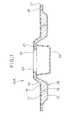
- Fig. 1 is a cross-sectional view of a ceiling member for an automobile interior according to the present invention.
- Fig. 2A and 2B are views illustrating how the ceiling member of Fig. 1 is made.
- Fig. 3 is a perspective view of the ceiling member.
- Fig. 4 is a graph showing the sound absorption coefficient of the ceiling member.
- Fig. 5A shows a ventilation test apparatus for use in evaluating ventilation characteristics of samples while Fig. 5B and 5C illustrate the samples set within the apparatus of Fig. 5A for evaluation of the ventilation characteristics.
- Fig. 6 is a cross-sectional view of an alternative to the ceiling member of Fig. 1.
- Fig. 7 is a cross-sectional view of a conventional ceiling member.
- Fig. 8 is a cross-sectional view of the ceiling member of Fig. 8 having formed therein an opening for attachment of an interior roof lamp.
- a ceiling member 10A for an automobile interior comprises a laminate 16 including a substrate 11, a covering material 13 applied to a surface 12 of the substrate 11, and an unventilated film 15 applied to a back surface 14 of the substrate 11 positioned opposite from the surface 12.
- the substrate 11, the covering material 13, and the unventilated film 15 are laminated together to provide the ceiling member 10A.
- Formed in the ceiling member 10A is an opening 23 for an interior roof lamp (not shown).
- An edge 17 of the substrate 11 is rendered unventilated in a manner as will be described later to there by provide a compressed hermetic portion 18.
- the substrate 11 also has an unventilated edge 19 defining the opening 23.
- the unventilated edge 19 is a compressed hermetic portion 21, as is the unventilated edge 17.
- Reference numeral 22 denotes a cover for the interior roof lamp.
- the substrate 11 is both ventilative and sound absorptive.
- the substrate 11 can be formed of, for example, a mixture of glass fibers and polypropylene resin.
- the covering material 13 is ventilative.
- the covering material 13 can be made of, for example, tricot or nonwoven fabric.
- the unventilated film 15 is a resinous film which prevents air from passing therethrough.
- glass fibers and polypropylene resin are mixed together to prepare the substrate 11, after which the unventilated film 15 is applied onto the back surface 14 of the substrate 11.
- the substrate 11 having the film 15 applied thereto is then heated to expand the glass fibers.
- the substrate 11 is thus expanded.
- the substrate 11 thus arranged is subsequently cooled.
- adhesive 24 is applied to the covering material 13.
- the substrate 11 having the film 15 applied thereto and the covering material 13 having the adhesive 24 applied thereto are set within the mold assembly 25, as shown in Fig. 2A.
- the mold assembly 25 includes an upper mold 26 and a lower mold 27.
- the mold assembly 25 can perform trimming, punching, and machining operations on the substrate 11 and the covering material 13 set therewithin.
- the mold assembly 25 is operated to raise the lower mold 27, as shown by an arrow 1 ⁇ of Fig. 2A.
- the upper and lower molds 26, 27 compress the covering material 13 and the substrate 11 together, such that the covering material 13 is applied to the substrate 11.
- part 28 of the substrate 11 is compressed to provide a hermetic part.
- the hermetic part is then punched to define the opening 23 (see Fig. 3). Accordingly, the unventilated edge 19 defining the opening 23 is formed.
- An edge (not shown) of the substrate 11 is also compressed using the mold assembly 25, thereby providing the hermetic portion 18. Namely, the unventilated edge 17 (see Fig. 1) is molded.
- the ceiling member 10A includes the substrate 11, the covering material 13 applied to the surface 12 of the substrate 11, and the unventilated film 15 applied onto the back surface 14.
- the unventilated edge 19 of the substrate 11 is the hermetic portion 21, as stated above. More specifically, the unventilated edge 19 of the substrate 11 contains glass fibers held or compressed together in such a manner as to provide no spaces therebetween. Provision of the hermetic portion 21 is advantageous because air 32, which has passed from passenger compartment 31 through the covering material 13 into the substrate 11, does not flow through the hermetic portion 21. It is to be understood that the hermetic portion 18 prevents the flow of air therethrough as does the hermetic portion 21.
- the covering material 13 is applied to the surface 12 of the substrate 11 while the unventilated film 15 is applied onto the back surface 14 of the substrate 11, sound produced within the passenger compartment 31 passes directly into the substrate 11. Little sound 35 passes out of the ceiling member 10A.
- Fig. 4 graphically shows the sound absorption coefficient of the ceiling member 10A.
- the axis of ordinates indicates the sound absorption coefficient of the ceiling member while the axis of abscissas indicates the frequency of the sound wave.
- a ceiling member having any part that is not yet rendered unventilated also exhibits the sound absorption coefficient as shown in Fig. 4.
- the sound absorption coefficient does not depend upon whether or not the ceiling member includes hermetic portions containing glass fibers held or compressed together in such a manner as to provide no spaces formed therebetween.
- Ventilation characteristics of ceiling members 50, 60 shown in Figs. 5B and 5C, respectively, were evaluated using a ventilation test apparatus 40 as shown in Fig. 5A.
- the apparatus 40 includes a mounting portion 42 to which a sample 41 (i.e., either of the ceiling members 50, 60) to be evaluated is attached, and a fan 44.
- the apparatus 40 is connected to a device 43 for drawing air out of the apparatus 40.
- the device 43 With the sample 41 mounted to the mounting portion 42, the device 43 is operated to draw air out of the apparatus 40 while the fan 44 is operated to raise dust 45, as shown in Fig. 5A. Under such a condition, a judge visually checks whether a surface 46 of the sample 41 is dirtied. More specifically, she checks to see if the dust 45 clings to the surface 46. If the dust 45 clings to the surface 45, she considers the sample 41 to have the ventilation characteristic. In other words, the sample 41 is considered to be ventilative.
- the ceiling member 50 has an edge 51 of thickness t1.
- the thickness t1 is 5mm.
- a portion 52 other than the edge 51 also has a thickness t2 of 5mm.
- the edge 51 is ventilative.
- a 100- ⁇ m-thick film 55 of polypropylene (PP) was initially applied to a back surface 54 of a substrate 53 containing 50 % by weight of glass fibers.
- the substrate 53 thus arranged was then heated to a temperature of 200 °C.
- the substrate 53 was held at 200 °C for 120 seconds to expand the glass fibers.
- the substrate 53 was thus expanded.
- the substrate 53 was subsequently cooled, after which adhesive was applied to a surface 56 of the substrate 53 positioned opposite from the back surface 54.
- a covering material 57 and the substrate 53 were set within a mold. The mold is operated such that the covering material 57 adheres to the surface 56 to thereby provide the ceiling member 50.
- the ceiling member 50 is punched to provide the edge 51.
- the ceiling member 50 was then set within the apparatus 40 for evaluation of the ventilation characteristic.
- the covering material 57 was found to be dirty. That is, the dust 45 clung to the covering material 57.
- the result indicates that the air passes through the covering material 57 into the substrate 53 and flows out of the edge 51, as shown by arrows 2 ⁇ , 3 ⁇ of Fig. 5B.
- the ceiling member 60 provided in accordance with the present invention has an unventilated edge 61 of thickness t3.
- the thickness t3 is 2.5mm.
- a portion 62 other than the edge 61 has a thickness t4 of 5mm.
- the unventilated edge 61 is formed in the manner as described above. Except that the edge 61 is rendered unventilated, the ceiling member 60 is molded in the same manner as the ceiling member 50.
- the ceiling member 60 was set within the apparatus 40 for evaluation of the ventilation characteristic. As a result, it was found that the covering material 57 was not dirtied. Namely, the covering material 57 had no dust 45 clung thereto. The result shows that air, which has passed through the covering material 57, is prevented from flowing through the substrate 53, as shown by an arrow 4 ⁇ of Fig. 5C. This means that harmful flow of air through the substrate 53 is not produced.
- FIG. 6 shows an alternative to the ceiling member 10A.
- a ceiling member 10B is comprised of the laminate 16 including the substrate 11, the covering material 13 applied to the surface 12, and the unventilated film 15 applied to the back surface 14.
- the substrate 11 includes unventilated edges 71, 72. More specifically, the edges 71, 72 are rendered unventilated because they are coated or otherwise impregnated with resins 73, 74. With this arrangement, air is not permitted to flow through the edges 71, 72.
- Provision of the unventilated edges 71, 72 makes it possible to stop the harmful flow of air through the substrate 11 without requiring any major change to the design of the ceiling member.
- the present invention has been described as being applied to the ceiling member having the opening 23 for the interior roof lamp, however, it may be altered such that the ceiling member has an opening for a sunroof.
- the substrate 11, the covering material 13, and the unventilated film 15 may be formed of a variety of other materials to provide their respective characteristics as stated above.
- a ceiling member (10) includes a ventilative and sound absorptive substrate (11), a ventilative covering material (13) applied to a surface (12) of the substrate (11), and an unventilated film (15) applied to a back surface (14) of the substrate (11).
- the ceiling member (10) has unventilated edges (17, 19).
- the unventilated edges (17, 19) are compressed hermetic portions (18, 21). The unventilated edges (17, 19) prevent air from passing therethrough.
Landscapes
- Engineering & Computer Science (AREA)
- Mechanical Engineering (AREA)
- Physics & Mathematics (AREA)
- Acoustics & Sound (AREA)
- Multimedia (AREA)
- Vehicle Interior And Exterior Ornaments, Soundproofing, And Insulation (AREA)
- Soundproofing, Sound Blocking, And Sound Damping (AREA)
Abstract
Description
- The present invention relates to a ceiling member for an automobile interior.
- Ceiling members for automobile interiors are known in the art. One example of such ceiling members is known from Japanese Utility Model Post-Exam Publication No. HEI 3-46996 entitled "VEHICLE INTERIOR MEMBER".
- With respect to Fig. 7 and Fig. 8 hereof, there is illustrated a
ceiling member 100 as disclosed in the publication. Theceiling member 100 includes a coveringmaterial 101 facing towards or exposed to a passenger compartment of an automobile, aventilative cushioning material 102 laminated to the coveringmaterial 101, aventilative foam 103 lying on thecushioning material 102, aresinous sheet 104 laid on thefoam 103, and alining material 105 applied to thesheet 104. The coveringmaterial 101 is made of a ventilative fabric. Thecushioning material 102 is formed of polyurethane slab. Thefoam 103 is made from such a ventilative and sound absorptive material as glass wool. Thesheet 104 is formed from an olefin-based material. Thesheet 104 prevents sound and air from passing therethrough. Thelining material 105 is made of nonwoven fabric which, when rubbed against the interior of an automobile body, produces no noise. - The
ceiling member 100 is advantageous because air, which has flowed from within the passenger compartment through the coveringmaterial 101 and thecushioning material 102 into thefoam 103, is prevented from passing through theresinous sheet 104, as shown by anarrow 7 ○ of Fig. 7. In other words, air does not flow through theceiling member 100. Therefore, no dust or the like clings to the covering 101. - Mounting an
interior roof lamp 106 to the interior of the automobile body requires forming anaperture 107 in theceiling member 100, as shown in Fig. 8. In such a case, however, harmful air could flow through thecushioning material 102 and anend surface 108 of theceiling member 100, as shown by anarrow 8 ○ of Fig. 8. This means that the harmful air undesirably passes through theceiling member 100. The thus arrangedceiling member 100 fails to exhibit a ventilation characteristic. - An object of the present invention is to provide a sound absorptive ceiling member for an automobile interior, which prevents harmful air from flowing therethrough.
- According to one aspect of the present invention, there is provided a ceiling member for an automobile interior, comprising: a ventilative and sound absorptive substrate; a ventilative covering material applied to a surface of the substrate; an unventilated film applied to a back surface of the substrate; and the substrate having edges unventilated.
- The unventilated edges of the substrate prevent air from passing therethrough. There is no longer harmful flow of air through the ceiling member.
- In a preferred form of the present invention, the edges are compressed hermetic portions.
- In a further preferred form of the present invention, the edges are impregnated with resins.
- The unventilated edges are the hermetic portions compressed such that the sound absorption coefficient of the substrate is maintained constant. Thus, the ceiling member maintains the sound absorption coefficient constant.
- The ceiling member is molded in such a manner that an edge of the substrate is compressed to provide the hermetic portion.
- During the molding of the ceiling member, the edge of the substrate is compressed to thereby provide the hermetic portion, and therefore there is no need for a particular process for compressing the edge of the substrate to provide the hermetic portion. The production cost of the ceiling member is maintained constant.
- Certain preferred embodiments of the present invention will be described in greater detail with reference to the accompanying sheets of drawings, in which;
- Fig. 1 is a cross-sectional view of a ceiling member for an automobile interior according to the present invention.
- Fig. 2A and 2B are views illustrating how the ceiling member of Fig. 1 is made.
- Fig. 3 is a perspective view of the ceiling member.
- Fig. 4 is a graph showing the sound absorption coefficient of the ceiling member.
- Fig. 5A shows a ventilation test apparatus for use in evaluating ventilation characteristics of samples while Fig. 5B and 5C illustrate the samples set within the apparatus of Fig. 5A for evaluation of the ventilation characteristics.
- Fig. 6 is a cross-sectional view of an alternative to the ceiling member of Fig. 1.
- Fig. 7 is a cross-sectional view of a conventional ceiling member.
- Fig. 8 is a cross-sectional view of the ceiling member of Fig. 8 having formed therein an opening for attachment of an interior roof lamp.
- The following description is merely exemplary in nature and is in no way intended to limit the invention, its application or uses.
- Referring now to drawings in which similar elements are numbered identically throughout, a description of preferred embodiments is provided.
- Referring to Fig. 1, a
ceiling member 10A for an automobile interior comprises alaminate 16 including asubstrate 11, a coveringmaterial 13 applied to asurface 12 of thesubstrate 11, and anunventilated film 15 applied to aback surface 14 of thesubstrate 11 positioned opposite from thesurface 12. In other words, thesubstrate 11, the coveringmaterial 13, and theunventilated film 15 are laminated together to provide theceiling member 10A. Formed in theceiling member 10A is an opening 23 for an interior roof lamp (not shown). Anedge 17 of thesubstrate 11 is rendered unventilated in a manner as will be described later to there by provide a compressedhermetic portion 18. Thesubstrate 11 also has anunventilated edge 19 defining theopening 23. Theunventilated edge 19 is a compressedhermetic portion 21, as is theunventilated edge 17.Reference numeral 22 denotes a cover for the interior roof lamp. - The
substrate 11 is both ventilative and sound absorptive. Thesubstrate 11 can be formed of, for example, a mixture of glass fibers and polypropylene resin. - The covering
material 13 is ventilative. The coveringmaterial 13 can be made of, for example, tricot or nonwoven fabric. - The
unventilated film 15 is a resinous film which prevents air from passing therethrough. - Discussion is made as to how the
ceiling member 10A is molded using amold assembly 25 as shown in Fig. 2A and Fig. 2B. - Initially, glass fibers and polypropylene resin are mixed together to prepare the
substrate 11, after which theunventilated film 15 is applied onto theback surface 14 of thesubstrate 11. Thesubstrate 11 having thefilm 15 applied thereto is then heated to expand the glass fibers. Thesubstrate 11 is thus expanded. Thesubstrate 11 thus arranged is subsequently cooled. Thereafter,adhesive 24 is applied to the coveringmaterial 13. Thesubstrate 11 having thefilm 15 applied thereto and the coveringmaterial 13 having the adhesive 24 applied thereto are set within themold assembly 25, as shown in Fig. 2A. - The
mold assembly 25 includes anupper mold 26 and alower mold 27. Themold assembly 25 can perform trimming, punching, and machining operations on thesubstrate 11 and the coveringmaterial 13 set therewithin. Themold assembly 25 is operated to raise thelower mold 27, as shown by an arrow 1 ○ of Fig. 2A. - The upper and
lower molds material 13 and thesubstrate 11 together, such that the coveringmaterial 13 is applied to thesubstrate 11. At the same time,part 28 of thesubstrate 11 is compressed to provide a hermetic part. The hermetic part is then punched to define the opening 23 (see Fig. 3). Accordingly, theunventilated edge 19 defining theopening 23 is formed. An edge (not shown) of thesubstrate 11 is also compressed using themold assembly 25, thereby providing thehermetic portion 18. Namely, the unventilated edge 17 (see Fig. 1) is molded. - Referring to Fig. 3, the
ceiling member 10A includes thesubstrate 11, the coveringmaterial 13 applied to thesurface 12 of thesubstrate 11, and theunventilated film 15 applied onto theback surface 14. Theunventilated edge 19 of thesubstrate 11 is thehermetic portion 21, as stated above. More specifically, theunventilated edge 19 of thesubstrate 11 contains glass fibers held or compressed together in such a manner as to provide no spaces therebetween. Provision of thehermetic portion 21 is advantageous becauseair 32, which has passed frompassenger compartment 31 through the coveringmaterial 13 into thesubstrate 11, does not flow through thehermetic portion 21. It is to be understood that thehermetic portion 18 prevents the flow of air therethrough as does thehermetic portion 21. - Since the covering
material 13 is applied to thesurface 12 of thesubstrate 11 while theunventilated film 15 is applied onto theback surface 14 of thesubstrate 11, sound produced within thepassenger compartment 31 passes directly into thesubstrate 11.Little sound 35 passes out of theceiling member 10A. This means that, with the sound absorption coefficient α maintained constant, thesubstrate 11 substantially absorbs the sound produced within thepassenger compartment 31. As used herein, the sound absorption coefficient α is expressed as follows:passenger compartment 31 and havingsound waves 33 arriving at thesubstrate 11 at a given angle of incidence and Sb is the loudness of sound havingsound waves 34 reflected by thesubstrate 11. - Fig. 4 graphically shows the sound absorption coefficient of the
ceiling member 10A. The axis of ordinates indicates the sound absorption coefficient of the ceiling member while the axis of abscissas indicates the frequency of the sound wave. A ceiling member having any part that is not yet rendered unventilated also exhibits the sound absorption coefficient as shown in Fig. 4. In other words, the sound absorption coefficient does not depend upon whether or not the ceiling member includes hermetic portions containing glass fibers held or compressed together in such a manner as to provide no spaces formed therebetween. - Ventilation characteristics of
ceiling members ventilation test apparatus 40 as shown in Fig. 5A. Theapparatus 40 includes a mountingportion 42 to which a sample 41 (i.e., either of theceiling members 50, 60) to be evaluated is attached, and afan 44. Theapparatus 40 is connected to adevice 43 for drawing air out of theapparatus 40. - With the
sample 41 mounted to the mountingportion 42, thedevice 43 is operated to draw air out of theapparatus 40 while thefan 44 is operated to raisedust 45, as shown in Fig. 5A. Under such a condition, a judge visually checks whether asurface 46 of thesample 41 is dirtied. More specifically, she checks to see if thedust 45 clings to thesurface 46. If thedust 45 clings to thesurface 45, she considers thesample 41 to have the ventilation characteristic. In other words, thesample 41 is considered to be ventilative. - In relation to Fig. 5B, the
ceiling member 50 has anedge 51 of thickness t1. The thickness t1 is 5mm. Aportion 52 other than theedge 51 also has a thickness t2 of 5mm. Theedge 51 is ventilative. - To mold the
ceiling member 50, a 100-µm-thick film 55 of polypropylene (PP) was initially applied to aback surface 54 of asubstrate 53 containing 50 % by weight of glass fibers. Thesubstrate 53 thus arranged was then heated to a temperature of 200 °C. Thesubstrate 53 was held at 200 °C for 120 seconds to expand the glass fibers. Thesubstrate 53 was thus expanded. Thesubstrate 53 was subsequently cooled, after which adhesive was applied to a surface 56 of thesubstrate 53 positioned opposite from theback surface 54. A coveringmaterial 57 and thesubstrate 53 were set within a mold. The mold is operated such that the coveringmaterial 57 adheres to the surface 56 to thereby provide theceiling member 50. Theceiling member 50 is punched to provide theedge 51. - The
ceiling member 50 was then set within theapparatus 40 for evaluation of the ventilation characteristic. As a result, the coveringmaterial 57 was found to be dirty. That is, thedust 45 clung to the coveringmaterial 57. The result indicates that the air passes through the coveringmaterial 57 into thesubstrate 53 and flows out of theedge 51, as shown byarrows 2 ○, 3 ○ of Fig. 5B. - As shown in Fig. 5C, the
ceiling member 60 provided in accordance with the present invention has anunventilated edge 61 of thickness t3. The thickness t3 is 2.5mm. Aportion 62 other than theedge 61 has a thickness t4 of 5mm. Theunventilated edge 61 is formed in the manner as described above. Except that theedge 61 is rendered unventilated, theceiling member 60 is molded in the same manner as theceiling member 50. - The
ceiling member 60 was set within theapparatus 40 for evaluation of the ventilation characteristic. As a result, it was found that the coveringmaterial 57 was not dirtied. Namely, the coveringmaterial 57 had nodust 45 clung thereto. The result shows that air, which has passed through the coveringmaterial 57, is prevented from flowing through thesubstrate 53, as shown by anarrow 4 ○ of Fig. 5C. This means that harmful flow of air through thesubstrate 53 is not produced. - Fig. 6 shows an alternative to the
ceiling member 10A. Aceiling member 10B is comprised of the laminate 16 including thesubstrate 11, the coveringmaterial 13 applied to thesurface 12, and theunventilated film 15 applied to theback surface 14. Thesubstrate 11 includesunventilated edges edges resins edges - Provision of the
unventilated edges substrate 11 without requiring any major change to the design of the ceiling member. - The present invention has been described as being applied to the ceiling member having the
opening 23 for the interior roof lamp, however, it may be altered such that the ceiling member has an opening for a sunroof. - The
substrate 11, the coveringmaterial 13, and theunventilated film 15 may be formed of a variety of other materials to provide their respective characteristics as stated above. - A ceiling member (10) includes a ventilative and sound absorptive substrate (11), a ventilative covering material (13) applied to a surface (12) of the substrate (11), and an unventilated film (15) applied to a back surface (14) of the substrate (11). The ceiling member (10) has unventilated edges (17, 19). The unventilated edges (17, 19) are compressed hermetic portions (18, 21). The unventilated edges (17, 19) prevent air from passing therethrough.
Claims (3)
- A ceiling member (10) for an automobile interior, comprising:a ventilative and sound absorptive substrate (11);a ventilative covering material (13) applied to a surface (12) of said substrate (11);an unventilated film (15) applied to a back surface (14) of said substrate (11); andsaid substrate (11) having edges (17, 19, 71, 72) unventilated.
- A ceiling member for an automobile interior as claimed in claim 1, wherein said edges (17, 19) are compressed hermetic portions (18, 21).
- A ceiling member for an automobile interior as claimed in claim 1, wherein said edges (71, 72) are impregnated with resins (73, 74).
Applications Claiming Priority (2)
| Application Number | Priority Date | Filing Date | Title |
|---|---|---|---|
| JP2000209648 | 2000-07-11 | ||
| JP2000209648A JP3929683B2 (en) | 2000-07-11 | 2000-07-11 | Car interior ceiling material |
Publications (2)
| Publication Number | Publication Date |
|---|---|
| EP1172200A1 true EP1172200A1 (en) | 2002-01-16 |
| EP1172200B1 EP1172200B1 (en) | 2007-06-13 |
Family
ID=18706022
Family Applications (1)
| Application Number | Title | Priority Date | Filing Date |
|---|---|---|---|
| EP01116866A Expired - Lifetime EP1172200B1 (en) | 2000-07-11 | 2001-07-10 | Ceiling member for automobile interior |
Country Status (3)
| Country | Link |
|---|---|
| EP (1) | EP1172200B1 (en) |
| JP (1) | JP3929683B2 (en) |
| DE (1) | DE60128864T2 (en) |
Families Citing this family (1)
| Publication number | Priority date | Publication date | Assignee | Title |
|---|---|---|---|---|
| JP2016203944A (en) * | 2015-04-28 | 2016-12-08 | 三和工業株式会社 | Molded ceiling material of vehicle and vehicle roof structure using the same |
Citations (5)
| Publication number | Priority date | Publication date | Assignee | Title |
|---|---|---|---|---|
| US4630707A (en) * | 1985-08-30 | 1986-12-23 | Nissan Motor Company, Limited | Sound-absorbing structure in vehicular compartment |
| JPH0434054A (en) * | 1990-05-24 | 1992-02-05 | Sekisui Chem Co Ltd | Production of porous composite material |
| DE4126884A1 (en) * | 1991-08-14 | 1993-02-18 | Perstorp Haeussling Gmbh | Mfg. sound-insulating laminate, useful esp. as interior lining for car - by heating glass mat-reinforced polypropylene@ sheet to form porous expanded layer, and laminating with nonwoven polypropylene@ fabric |
| JPH05170033A (en) * | 1991-12-26 | 1993-07-09 | Sekisui Chem Co Ltd | Ceiling material for automobile |
| GB2265569A (en) * | 1992-04-04 | 1993-10-06 | Daimler Benz Ag | A cowling for internal-combustion engines of motor vehicles |
-
2000
- 2000-07-11 JP JP2000209648A patent/JP3929683B2/en not_active Expired - Fee Related
-
2001
- 2001-07-10 DE DE60128864T patent/DE60128864T2/en not_active Expired - Fee Related
- 2001-07-10 EP EP01116866A patent/EP1172200B1/en not_active Expired - Lifetime
Patent Citations (5)
| Publication number | Priority date | Publication date | Assignee | Title |
|---|---|---|---|---|
| US4630707A (en) * | 1985-08-30 | 1986-12-23 | Nissan Motor Company, Limited | Sound-absorbing structure in vehicular compartment |
| JPH0434054A (en) * | 1990-05-24 | 1992-02-05 | Sekisui Chem Co Ltd | Production of porous composite material |
| DE4126884A1 (en) * | 1991-08-14 | 1993-02-18 | Perstorp Haeussling Gmbh | Mfg. sound-insulating laminate, useful esp. as interior lining for car - by heating glass mat-reinforced polypropylene@ sheet to form porous expanded layer, and laminating with nonwoven polypropylene@ fabric |
| JPH05170033A (en) * | 1991-12-26 | 1993-07-09 | Sekisui Chem Co Ltd | Ceiling material for automobile |
| GB2265569A (en) * | 1992-04-04 | 1993-10-06 | Daimler Benz Ag | A cowling for internal-combustion engines of motor vehicles |
Non-Patent Citations (2)
| Title |
|---|
| DATABASE WPI Section Ch Week 199212, Derwent World Patents Index; Class A32, AN 1992-091809, XP002181261 * |
| DATABASE WPI Section Ch Week 199332, Derwent World Patents Index; Class A17, AN 1993-252421, XP002181260 * |
Also Published As
| Publication number | Publication date |
|---|---|
| JP2002019536A (en) | 2002-01-23 |
| DE60128864D1 (en) | 2007-07-26 |
| EP1172200B1 (en) | 2007-06-13 |
| JP3929683B2 (en) | 2007-06-13 |
| DE60128864T2 (en) | 2008-06-26 |
Similar Documents
| Publication | Publication Date | Title |
|---|---|---|
| US4476183A (en) | Thermoformable laminate structure with improved acoustical absorption | |
| US4432580A (en) | Interior lining for motor vehicles | |
| KR910008871B1 (en) | Headliner with improved sound-absorbing properties | |
| US6204209B1 (en) | Acoustical composite headliner | |
| US7070848B2 (en) | Vehicle acoustic barrier | |
| US5504282A (en) | Sound transmission and absorption control media | |
| US4729917A (en) | Method and laminate for thermoforming automobile headliners and like three dimensional objects | |
| US6898901B2 (en) | Sound-absorbing composites and shield devices employing same | |
| US20030124940A1 (en) | Tunable or adjustable liner for selectively absorbing sound energy and related methods | |
| KR100620635B1 (en) | Roof lining of vehicles and production method thereof | |
| US20160307555A1 (en) | Acoustic insulator mat with liquid applied sprayable coating and method for making the same | |
| MX2007009627A (en) | Sound-absorbent lining for motor vehicles, more particularly engine bonnet lining. | |
| US6572976B1 (en) | Shield for water and sound | |
| EP1172200A1 (en) | Ceiling member for automobile interior | |
| JP3703130B2 (en) | Sound insulation for vehicles | |
| JP2002215169A (en) | Acoustic material for vehicle | |
| JPH09251295A (en) | Sound absorbing material and sound insulation cover | |
| KR100493758B1 (en) | Cover for Automobile sunroof | |
| JP2002220009A (en) | Insulator for automobile | |
| JP3188592B2 (en) | Prevention of dirt on sound absorbing material | |
| JPH06156054A (en) | Duct structure for low noise air conditioning | |
| JP7564612B2 (en) | Vehicle soundproofing materials | |
| JPH0516505U (en) | Interior materials for vehicles | |
| JPH06344486A (en) | Sound insulation structure and manufacturing method thereof | |
| JP2006069256A (en) | Interior material for automobile |
Legal Events
| Date | Code | Title | Description |
|---|---|---|---|
| PUAI | Public reference made under article 153(3) epc to a published international application that has entered the european phase |
Free format text: ORIGINAL CODE: 0009012 |
|
| AK | Designated contracting states |
Kind code of ref document: A1 Designated state(s): DE GB Kind code of ref document: A1 Designated state(s): AT BE CH CY DE DK ES FI FR GB GR IE IT LI LU MC NL PT SE TR |
|
| AX | Request for extension of the european patent |
Free format text: AL;LT;LV;MK;RO;SI |
|
| 17P | Request for examination filed |
Effective date: 20020604 |
|
| 17Q | First examination report despatched |
Effective date: 20020805 |
|
| AKX | Designation fees paid |
Free format text: DE GB |
|
| 17Q | First examination report despatched |
Effective date: 20020805 |
|
| GRAP | Despatch of communication of intention to grant a patent |
Free format text: ORIGINAL CODE: EPIDOSNIGR1 |
|
| GRAS | Grant fee paid |
Free format text: ORIGINAL CODE: EPIDOSNIGR3 |
|
| GRAA | (expected) grant |
Free format text: ORIGINAL CODE: 0009210 |
|
| AK | Designated contracting states |
Kind code of ref document: B1 Designated state(s): DE GB |
|
| REG | Reference to a national code |
Ref country code: GB Ref legal event code: FG4D |
|
| REF | Corresponds to: |
Ref document number: 60128864 Country of ref document: DE Date of ref document: 20070726 Kind code of ref document: P |
|
| PLBE | No opposition filed within time limit |
Free format text: ORIGINAL CODE: 0009261 |
|
| STAA | Information on the status of an ep patent application or granted ep patent |
Free format text: STATUS: NO OPPOSITION FILED WITHIN TIME LIMIT |
|
| 26N | No opposition filed |
Effective date: 20080314 |
|
| PGFP | Annual fee paid to national office [announced via postgrant information from national office to epo] |
Ref country code: DE Payment date: 20080717 Year of fee payment: 8 |
|
| PGFP | Annual fee paid to national office [announced via postgrant information from national office to epo] |
Ref country code: GB Payment date: 20080716 Year of fee payment: 8 |
|
| GBPC | Gb: european patent ceased through non-payment of renewal fee |
Effective date: 20090710 |
|
| PG25 | Lapsed in a contracting state [announced via postgrant information from national office to epo] |
Ref country code: GB Free format text: LAPSE BECAUSE OF NON-PAYMENT OF DUE FEES Effective date: 20090710 |
|
| PG25 | Lapsed in a contracting state [announced via postgrant information from national office to epo] |
Ref country code: DE Free format text: LAPSE BECAUSE OF NON-PAYMENT OF DUE FEES Effective date: 20100202 |