EP1170490A2 - Verbrennungsmotor - Google Patents
Verbrennungsmotor Download PDFInfo
- Publication number
- EP1170490A2 EP1170490A2 EP01116276A EP01116276A EP1170490A2 EP 1170490 A2 EP1170490 A2 EP 1170490A2 EP 01116276 A EP01116276 A EP 01116276A EP 01116276 A EP01116276 A EP 01116276A EP 1170490 A2 EP1170490 A2 EP 1170490A2
- Authority
- EP
- European Patent Office
- Prior art keywords
- valve
- combustion engine
- blow
- pressure
- internal combustion
- Prior art date
- Legal status (The legal status is an assumption and is not a legal conclusion. Google has not performed a legal analysis and makes no representation as to the accuracy of the status listed.)
- Withdrawn
Links
- 238000002485 combustion reaction Methods 0.000 title claims description 16
- 239000000203 mixture Substances 0.000 claims description 14
- 230000001105 regulatory effect Effects 0.000 claims description 10
- 230000001276 controlling effect Effects 0.000 claims 1
- 230000006399 behavior Effects 0.000 description 2
- 230000006870 function Effects 0.000 description 2
- 238000005259 measurement Methods 0.000 description 2
- 230000002411 adverse Effects 0.000 description 1
- 238000007664 blowing Methods 0.000 description 1
- 238000000034 method Methods 0.000 description 1
- 238000005086 pumping Methods 0.000 description 1
- 238000010561 standard procedure Methods 0.000 description 1
Images
Classifications
-
- F—MECHANICAL ENGINEERING; LIGHTING; HEATING; WEAPONS; BLASTING
- F02—COMBUSTION ENGINES; HOT-GAS OR COMBUSTION-PRODUCT ENGINE PLANTS
- F02D—CONTROLLING COMBUSTION ENGINES
- F02D23/00—Controlling engines characterised by their being supercharged
- F02D23/02—Controlling engines characterised by their being supercharged the engines being of fuel-injection type
-
- F—MECHANICAL ENGINEERING; LIGHTING; HEATING; WEAPONS; BLASTING
- F02—COMBUSTION ENGINES; HOT-GAS OR COMBUSTION-PRODUCT ENGINE PLANTS
- F02D—CONTROLLING COMBUSTION ENGINES
- F02D41/00—Electrical control of supply of combustible mixture or its constituents
- F02D41/0002—Controlling intake air
- F02D41/0007—Controlling intake air for control of turbo-charged or super-charged engines
-
- F—MECHANICAL ENGINEERING; LIGHTING; HEATING; WEAPONS; BLASTING
- F02—COMBUSTION ENGINES; HOT-GAS OR COMBUSTION-PRODUCT ENGINE PLANTS
- F02D—CONTROLLING COMBUSTION ENGINES
- F02D2200/00—Input parameters for engine control
- F02D2200/02—Input parameters for engine control the parameters being related to the engine
- F02D2200/04—Engine intake system parameters
- F02D2200/0406—Intake manifold pressure
-
- Y—GENERAL TAGGING OF NEW TECHNOLOGICAL DEVELOPMENTS; GENERAL TAGGING OF CROSS-SECTIONAL TECHNOLOGIES SPANNING OVER SEVERAL SECTIONS OF THE IPC; TECHNICAL SUBJECTS COVERED BY FORMER USPC CROSS-REFERENCE ART COLLECTIONS [XRACs] AND DIGESTS
- Y02—TECHNOLOGIES OR APPLICATIONS FOR MITIGATION OR ADAPTATION AGAINST CLIMATE CHANGE
- Y02T—CLIMATE CHANGE MITIGATION TECHNOLOGIES RELATED TO TRANSPORTATION
- Y02T10/00—Road transport of goods or passengers
- Y02T10/10—Internal combustion engine [ICE] based vehicles
- Y02T10/12—Improving ICE efficiencies
Definitions
- the invention relates to an internal combustion engine, in particular a stationary gas engine a compressor arranged in the intake tract, in particular an exhaust gas turbocharger, with a downstream of the compressor electrically controllable blow-off valve and with a Pressure sensor for recording the actual pressure value of the mixture in the range of Blowoff valve.
- US 5,526,645 shows an air pressure control system for a diesel gas internal combustion engine or for a spark-ignited gas internal combustion engine, in which an air discharge valve is arranged in a bypass line, air being connected to the bypass line led around a turbocharger or air through the bypass line and turbocharger is blown over.
- the aim of this arrangement is to inject the air pressure behind the turbocharger To regulate dependency of various measured engine state parameters.
- This concept can for generic internal combustion engines, which primarily have a Throttle valve are regulated, not to improve the load cut-off behavior can be used because, among other things, the blowing of air-gas mixture through a Turbocharger and a bypass line the mixing ratio of the air-gas mixture would adversely affect and is therefore not practicable.
- the object of the invention is to provide an internal combustion engine of the type mentioned a reliable control for the relief valve, especially to avoid the Turbocharger pumps to provide.
- the invention assumes that at a certain combustion gas-air ratio of the mixture (and at a certain temperature) a predetermined relationship there is between the engine power and the mixture pressure in the intake tract.
- This Context is used according to the invention to a pressure-controlled control for the Blow-off valve to create.
- the relationship between the engine power and the pressure setpoint can be determined either empirically or from measurements. Then he can for example as a formula with certain parameters or as an assignment table can be saved.
- this facility is capable of actually measured engine power and a corrective incoming temperature value a pressure setpoint to achieve.
- the blow-off valve is now regulated until the actual pressure value reaches the pressure setpoint. in the generally one will get this pressure setpoint above which the relief valve opens set a small amount (e.g. 0.2 to 0.3 bar) higher than this empirical and measured relationship between the quantities involved in a Engine without blow-off valve. So you conveniently hold one with the blow-off valve Safety distance with regard to the regulated pressure point, so that is a normal one Engine control, which acts on the throttle valve, is still sufficiently effective Has influence. When the throttle valve is fully open, the engine speed can not yet be intercepted, albeit a large part of the "excess performance" via the Blow-off valve is discharged. The actual reduction of the overspeed must then over the mentioned throttle control. However, the throttle valve must now the low pressure does not close very far to keep the engine power below to lower the given load.
- a small amount e.g. 0.2 to 0.3 bar
- the blow-off valve becomes closed, which causes as much mass flow to the engine and also to Turbine arrives. This allows the engine power as well as the turbocharger speed on one are kept sufficiently high so that the engine speed does not drop too much.
- a device for detecting the Speed of the motor is provided, with a comparison device, the relief valve regardless of the signal from the control device closes if the speed is below a Predefinable setpoint lies or falls.
- the regulation according to the invention remains a pressure-controlled regulation.
- the speed signal is independent of this pressure-led Regulation used to close the relief valve when the speed is below one Setpoint falls.
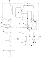
- the figure shows an internal combustion engine according to the invention using a Embodiment.
- the internal combustion engine M in particular a multi-cylinder gas engine, has an air-gas mixer 2 in its intake tract 1.
- the mixture is over the Turbocharger compresses and reaches the inlet valves of the throttle valve 4 Internal combustion engine M.
- a possible mixture cooler is not shown here.
- the turbine 6 of the turbocharger is in the exhaust tract 5 of the engine M in a manner known per se arranged.
- Blow-off valve 7 In the intake tract 1 of the internal combustion engine M there is an electrically controllable one Blow-off valve 7, the regulation of which is the subject of the present invention.
- the Blow-off valve can be controlled via a control line 8 in its degree of opening or closing.
- the previously saved relationship between engine power and pressure setpoint is in the figure schematically represented by a characteristic curve.
- This characteristic can be empirical or can be determined by measurements. You can, for example, in the form of a formula stored parameters or be stored as an assignment table. As a correction value the mixture temperature T can also be taken into account for the relationship a temperature sensor 12 is detected.
- the device shown now works as follows: The engine power N currently recorded and the mixture temperature T are supplied to the device 10. This then determines a set value for the mixture pressure. By opening and closing the blow-off valve 7 then regulates the regulating device 11 thereon Mixture pressure, the actual pressure value in the range of Blow-off valve 7 is detected.
- the speed n of the motor is detected via a device 14.
- a comparison device 15 detects this engine power N and in any case closes the blow-off valve 7 when the actual speed falls below the predetermined target speed n MIN . This also happens if the pressure-controlled control would open the blow-off valve via the control device 11.
Landscapes
- Engineering & Computer Science (AREA)
- Chemical & Material Sciences (AREA)
- Combustion & Propulsion (AREA)
- Mechanical Engineering (AREA)
- General Engineering & Computer Science (AREA)
- Supercharger (AREA)
- Output Control And Ontrol Of Special Type Engine (AREA)
- Lubrication Details And Ventilation Of Internal Combustion Engines (AREA)
Abstract
Description
- eine Einrichtung zum Erfassen der Motorleistung,
- eine Einrichtung zum Errechnen eines Druck-Sollwertes in Abhängigkeit von der erfaßten Motorleistung und von einem in einem Speicher vorab gespeicherten Zusammenhang zwischen Motorleistung und Druck-Sollwert, und
- eine Regeleinrichtung zum Regeln des Abblasventils, bis der Druck-Istwert den errechneten Druck-Sollwert erreicht.
- eine Einrichtung 9 zum Erfassen der Motorleistung N,
- eine Einrichtung 10 zum Errechnen eines Druck-Sollwertes Psoll in Abhängigkeit von der erfaßten Motorleistung N und von einem im Speicher vorab gespeicherten Zusammenhang zwischen Motorleistung N und Druck-Sollwert Psoll, und
- eine Regeleinrichtung 11 zum Regeln des Abblasventiles 7, bis der Druck-Istwert Pist (Sensor 13) den errechneten Druck-Sollwert erreicht.
Claims (4)
- Verbrennungsmotor, insbesondere stationärer Gasmotor, mit einem im Ansaugtrakt angeordnetem Verdichter, insbesondere Abgasturbolader, mit einem dem Verdichter nachgeschalteten elektrisch ansteuerbaren Abblasventil und mit einem Druckaufnehmer zum Erfassen des Druck-Istwertes des Gemisches im Bereich des Abblasventils, gekennzeichnet durcheine Einrichtung (9) zum Erfassen der Motorleistung (N),eine Einrichtung (10) zum Errechnen eines Druck-Sollwertes in Abhängigkeit von der erfaßten Motorleistung und von einem in einem Speicher vorab gespeicherten Zusammenhang zwischen Motorleistung (N) und Druck-Sollwert (Psoll), undeine Regeleinrichtung (11) zum Regeln des Abblasventils (7), bis der Druck-Istwert (Pist) den errechneten Druck-Sollwert (Psoll) erreicht.
- Verbrennungsmotor nach Anspruch 1, dadurch gekennzeichnet, daß weiters ein Temperatursensor (12) zum Erfassen der Gemischtemperatur (T) vor den Einlaßventilen vorgesehen ist, wobei die Einrichtung (10) zum Errechnen des Druck-Sollwertes neben der Motorleistung (N) auch die erfaßte Gemischtemperatur (T) gemäß einem vorab gespeicherten Zusammenhang berücksichtigt.
- Verbrennungsmotor nach Anspruch 1 oder 2, dadurch gekennzeichnet, daß das Abblasventil (7) zwischen dem Verdichter (3) und einer Drosselklappe (4) im Ansaugtrakt (1) angeordnet ist.
- Verbrennungsmotor nach einem der Ansprüche 1 bis 3, dadurch gekennzeichnet, daß weiters eine Einrichtung (14) zum Erfassen der Drehzahl (n) des Motors (M) vorgesehen ist, wobei eine Vergleichseinrichtung (15) das Abblasventil (7) unabhängig vom Signal aus der Regeleinrichtung (11) schließt, wenn die Drehzahl (n) unter einem vorgebbaren Sollwert (nMIN) liegt bzw. fällt.
Applications Claiming Priority (2)
| Application Number | Priority Date | Filing Date | Title |
|---|---|---|---|
| AT0116300A AT412805B (de) | 2000-07-07 | 2000-07-07 | Verbrennungsmotor |
| AT116300 | 2000-07-07 |
Publications (2)
| Publication Number | Publication Date |
|---|---|
| EP1170490A2 true EP1170490A2 (de) | 2002-01-09 |
| EP1170490A3 EP1170490A3 (de) | 2005-08-10 |
Family
ID=3686406
Family Applications (1)
| Application Number | Title | Priority Date | Filing Date |
|---|---|---|---|
| EP01116276A Withdrawn EP1170490A3 (de) | 2000-07-07 | 2001-07-05 | Verbrennungsmotor |
Country Status (3)
| Country | Link |
|---|---|
| US (1) | US6457312B2 (de) |
| EP (1) | EP1170490A3 (de) |
| AT (1) | AT412805B (de) |
Cited By (2)
| Publication number | Priority date | Publication date | Assignee | Title |
|---|---|---|---|---|
| US7240669B2 (en) | 2003-08-29 | 2007-07-10 | Daimlerchrysler Ag | Method of operating an internal combustion engine with a dual fuel injection system |
| EP3399172A4 (de) * | 2015-12-28 | 2019-08-28 | Kawasaki Jukogyo Kabushiki Kaisha | Gasmotorsystem |
Families Citing this family (8)
| Publication number | Priority date | Publication date | Assignee | Title |
|---|---|---|---|---|
| US7086230B2 (en) * | 2000-08-21 | 2006-08-08 | Brp-Rotax Gmbh & Co. Kg | Pop-off valve for an aircraft engine having a turbocharger control system and propeller control system by stepper motor |
| DE10062391A1 (de) * | 2000-12-14 | 2002-06-20 | Opel Adam Ag | Mit verschiedenen Kraftstoffen wahlweise betreibbare Brennkraftmaschine, insbesondere für einen Kraftfahrzeugantrieb |
| NZ521672A (en) * | 2002-09-30 | 2004-02-27 | John Adrian | Blow-off Valve |
| GB0323982D0 (en) * | 2003-10-13 | 2003-11-19 | Microgen Energy Ltd | Improvements relating to the operation of an engine |
| US6990814B2 (en) * | 2003-12-18 | 2006-01-31 | Caterpillar Inc. | Engine turbocharger control management system |
| US7010914B1 (en) * | 2005-03-04 | 2006-03-14 | Southwest Research Institute | Method for controlling boost pressure in a turbocharged diesel engine |
| EP2014894B1 (de) * | 2007-07-09 | 2010-10-13 | Magneti Marelli S.p.A. | Verfahren zur Steuerung einer durch einen Turbolader aufgeladenen Brennkraftmaschine |
| US8136357B2 (en) * | 2008-08-27 | 2012-03-20 | Honda Motor Co., Ltd. | Turbocharged engine using an air bypass valve |
Citations (1)
| Publication number | Priority date | Publication date | Assignee | Title |
|---|---|---|---|---|
| US5526645A (en) | 1995-07-26 | 1996-06-18 | Powerhouse Diesel Services, Inc. | Dual-fuel and spark ignited gas internal combustion engine excess air control system and method |
Family Cites Families (16)
| Publication number | Priority date | Publication date | Assignee | Title |
|---|---|---|---|---|
| DE1751061C3 (de) * | 1968-03-27 | 1974-07-04 | Michael Dipl.-Ing. Rolle May (Schweiz) | Mittels Abgasturbolader aufgeladene, fremdgezündete Brennkraftmaschine |
| DE2441804A1 (de) * | 1974-08-31 | 1976-03-11 | Daimler Benz Ag | Insbesondere nach dem otto-verfahren arbeitende brennkraftmaschine, vorzugsweise kraftfahrzeug-brennkraftmaschinen |
| DE3011203C2 (de) * | 1980-03-22 | 1986-06-19 | Dr.Ing.H.C. F. Porsche Ag, 7000 Stuttgart | Aufgeladene Brennkraftmaschine für Kraftfahrzeuge |
| DE3118501A1 (de) * | 1981-05-09 | 1982-12-02 | Bayerische Motoren Werke AG, 8000 München | Sicherheitsvorrichtung fuer eine diesel-einspritz-brennkraftmaschine mit abgasturbolader |
| US4691521A (en) * | 1984-04-25 | 1987-09-08 | Nissan Motor Co., Ltd. | Supercharger pressure control system for internal combustion engine with turbocharger |
| JPS6165020A (ja) * | 1984-09-05 | 1986-04-03 | Nissan Motor Co Ltd | タ−ボチヤ−ジヤの過給圧制御装置 |
| DE3623541A1 (de) * | 1986-07-12 | 1988-02-11 | Porsche Ag | Brennkraftmaschine mit wenigstens einem turbolader |
| JPS63108662A (ja) | 1986-10-24 | 1988-05-13 | Sanyo Electric Co Ltd | 薄型電池 |
| JP2579936B2 (ja) * | 1987-04-02 | 1997-02-12 | マツダ株式会社 | 過給機付エンジンの空燃比制御装置 |
| JPH01280635A (ja) * | 1988-04-30 | 1989-11-10 | Suzuki Motor Co Ltd | 内燃機関の過給圧制御装置 |
| JPH02227522A (ja) * | 1989-02-28 | 1990-09-10 | Fuji Heavy Ind Ltd | 過給圧制御装置 |
| EP0450787A3 (en) * | 1990-04-04 | 1992-09-09 | Lucas Industries Public Limited Company | Engine control system and method |
| DE19502150C1 (de) * | 1995-01-25 | 1996-05-23 | Bosch Gmbh Robert | System zur Regelung der Aufladung einer Brennkraftmaschine |
| DE59608240D1 (de) * | 1995-08-04 | 2002-01-03 | Jenbacher Ag Jenbach | Einrichtung zum Regeln einer Motorgrösse, insbesondere der Leistung oder der Drehzahl eines Verbrennungsmotors |
| DE19620778C1 (de) * | 1996-05-23 | 1997-08-21 | Daimler Benz Ag | Verfahren zur Regelung des Druckes im Ansaugkanal einer Brennkraftmaschine und Vorrichtung zur Durchführung des Verfahrens |
| JP3828209B2 (ja) * | 1996-09-10 | 2006-10-04 | 有限会社日高エンジニアリング | 過給式エンジンの吸気装置 |
-
2000
- 2000-07-07 AT AT0116300A patent/AT412805B/de not_active IP Right Cessation
-
2001
- 2001-07-05 EP EP01116276A patent/EP1170490A3/de not_active Withdrawn
- 2001-07-06 US US09/900,665 patent/US6457312B2/en not_active Expired - Lifetime
Patent Citations (1)
| Publication number | Priority date | Publication date | Assignee | Title |
|---|---|---|---|---|
| US5526645A (en) | 1995-07-26 | 1996-06-18 | Powerhouse Diesel Services, Inc. | Dual-fuel and spark ignited gas internal combustion engine excess air control system and method |
Cited By (2)
| Publication number | Priority date | Publication date | Assignee | Title |
|---|---|---|---|---|
| US7240669B2 (en) | 2003-08-29 | 2007-07-10 | Daimlerchrysler Ag | Method of operating an internal combustion engine with a dual fuel injection system |
| EP3399172A4 (de) * | 2015-12-28 | 2019-08-28 | Kawasaki Jukogyo Kabushiki Kaisha | Gasmotorsystem |
Also Published As
| Publication number | Publication date |
|---|---|
| EP1170490A3 (de) | 2005-08-10 |
| AT412805B (de) | 2005-07-25 |
| US20020002826A1 (en) | 2002-01-10 |
| US6457312B2 (en) | 2002-10-01 |
| ATA11632000A (de) | 2004-12-15 |
Similar Documents
| Publication | Publication Date | Title |
|---|---|---|
| EP0084037B1 (de) | Einrichtung zum steueren des ladedrucks bei einer mit aufladung betriebenen brennkraftmaschine | |
| US6055810A (en) | Feedback control of direct injected engines by use of a smoke sensor | |
| DE69621793T2 (de) | Abgasrezirkulationssystem für brennkraftmaschine | |
| EP1179128B1 (de) | Verfahren und vorrichtung zur regelung des ladedrucks einer brennkraftmaschine | |
| EP2260193B1 (de) | Verfahren zur regelung einer gasturbine in einem kraftwerk und kraftwerk zur durchführung des verfahrens | |
| DE69528013T2 (de) | Verwaltungssystem zur Turboladerregelung | |
| EP1474595B1 (de) | Verfahren zum betrieb einer gasturbogruppe | |
| EP0757169B1 (de) | Einrichtung zum Regeln einer Motorgrösse, insbesondere der Leistung oder der Drehzahl eines Verbrennungsmotors | |
| DE102009055236B4 (de) | Verfahren und Vorrichtung zur Regelung eines Abgasturboladers | |
| DE7529221U (de) | Einrichtung zur aufladung eines verbrennungsmotors, insbesondere eines dieselmotors | |
| DE1751061B2 (de) | Mittels Abgasturbolader aufge ladene, fremdgezundete Brennkraft maschine | |
| DE69732884T2 (de) | Elektronisch steuerbares Abblaseventil | |
| DE10125335A1 (de) | Brennkammerdruckschutzvorrichtung und -verfahren für einen turboaufgeladenen Verbrennungsmotor | |
| DE102010051129A1 (de) | Zweischleifenregelsysteme und -verfahren für einen sequentiellen Turbolader | |
| US5307619A (en) | Automatic NOx control for a gas turbine | |
| AT412805B (de) | Verbrennungsmotor | |
| DE102021131487A1 (de) | Verfahren zum steuern eines turboladers | |
| DE3040139A1 (de) | Regelsystem fuer eine gasturbine | |
| DE19808829A1 (de) | Gasmotor | |
| DE68920640T2 (de) | Steuereinrichtung für einen Turbolader bei einem Verbrennungsmotor. | |
| EP3183446B1 (de) | Kompressoreinheit und verfahren zu deren betrieb | |
| DE60215903T2 (de) | Verfahren zur Steuerung eines Abgasturboladers mit verstellbarer Turbinengeometrie | |
| DE10007669B4 (de) | Verfahren zur Regelung eines Verdichters, insbesondere eines Verdichters im Ansaugtrakt einer Brennkraftmaschine | |
| DE19754353C2 (de) | Gasmotor | |
| DE112012005550T5 (de) | Kompressorführungsschaufel und Vorsteuerung für einen Gasturbinenmotor |
Legal Events
| Date | Code | Title | Description |
|---|---|---|---|
| PUAI | Public reference made under article 153(3) epc to a published international application that has entered the european phase |
Free format text: ORIGINAL CODE: 0009012 |
|
| AK | Designated contracting states |
Kind code of ref document: A2 Designated state(s): AT BE CH CY DE DK ES FI FR GB GR IE IT LI LU MC NL PT SE TR |
|
| AX | Request for extension of the european patent |
Free format text: AL;LT;LV;MK;RO;SI |
|
| PUAL | Search report despatched |
Free format text: ORIGINAL CODE: 0009013 |
|
| AK | Designated contracting states |
Kind code of ref document: A3 Designated state(s): AT BE CH CY DE DK ES FI FR GB GR IE IT LI LU MC NL PT SE TR |
|
| AX | Request for extension of the european patent |
Extension state: AL LT LV MK RO SI |
|
| AKX | Designation fees paid | ||
| REG | Reference to a national code |
Ref country code: DE Ref legal event code: 8566 |
|
| STAA | Information on the status of an ep patent application or granted ep patent |
Free format text: STATUS: THE APPLICATION IS DEEMED TO BE WITHDRAWN |
|
| 18D | Application deemed to be withdrawn |
Effective date: 20060214 |