EP1170246A1 - Capping of bottles - Google Patents
Capping of bottles Download PDFInfo
- Publication number
- EP1170246A1 EP1170246A1 EP00305589A EP00305589A EP1170246A1 EP 1170246 A1 EP1170246 A1 EP 1170246A1 EP 00305589 A EP00305589 A EP 00305589A EP 00305589 A EP00305589 A EP 00305589A EP 1170246 A1 EP1170246 A1 EP 1170246A1
- Authority
- EP
- European Patent Office
- Prior art keywords
- curl portion
- curl
- bottle
- capping
- crown closure
- Prior art date
- Legal status (The legal status is an assumption and is not a legal conclusion. Google has not performed a legal analysis and makes no representation as to the accuracy of the status listed.)
- Withdrawn
Links
- 239000011324 bead Substances 0.000 claims abstract description 22
- 239000000463 material Substances 0.000 claims abstract description 16
- 230000002093 peripheral effect Effects 0.000 claims abstract description 8
- 238000002407 reforming Methods 0.000 claims description 16
- 238000000034 method Methods 0.000 claims description 15
- 229910052751 metal Inorganic materials 0.000 claims description 3
- 239000002184 metal Substances 0.000 claims description 3
- 229910000831 Steel Inorganic materials 0.000 claims description 2
- 239000004411 aluminium Substances 0.000 claims description 2
- 229910052782 aluminium Inorganic materials 0.000 claims description 2
- XAGFODPZIPBFFR-UHFFFAOYSA-N aluminium Chemical compound [Al] XAGFODPZIPBFFR-UHFFFAOYSA-N 0.000 claims description 2
- 239000002861 polymer material Substances 0.000 claims description 2
- 239000010959 steel Substances 0.000 claims description 2
- JEIPFZHSYJVQDO-UHFFFAOYSA-N iron(III) oxide Inorganic materials O=[Fe]O[Fe]=O JEIPFZHSYJVQDO-UHFFFAOYSA-N 0.000 description 3
- 238000007789 sealing Methods 0.000 description 3
- ONBQEOIKXPHGMB-VBSBHUPXSA-N 1-[2-[(2s,3r,4s,5r)-3,4-dihydroxy-5-(hydroxymethyl)oxolan-2-yl]oxy-4,6-dihydroxyphenyl]-3-(4-hydroxyphenyl)propan-1-one Chemical compound O[C@@H]1[C@H](O)[C@@H](CO)O[C@H]1OC1=CC(O)=CC(O)=C1C(=O)CCC1=CC=C(O)C=C1 ONBQEOIKXPHGMB-VBSBHUPXSA-N 0.000 description 2
- 229940126142 compound 16 Drugs 0.000 description 2
- 239000002245 particle Substances 0.000 description 2
- 229920001944 Plastisol Polymers 0.000 description 1
- 239000011248 coating agent Substances 0.000 description 1
- 238000000576 coating method Methods 0.000 description 1
- 150000001875 compounds Chemical class 0.000 description 1
- 238000011109 contamination Methods 0.000 description 1
- 239000000428 dust Substances 0.000 description 1
- 238000010410 dusting Methods 0.000 description 1
- 239000011521 glass Substances 0.000 description 1
- 239000004033 plastic Substances 0.000 description 1
- 229920003023 plastic Polymers 0.000 description 1
- 239000004999 plastisol Substances 0.000 description 1
- 230000001737 promoting effect Effects 0.000 description 1
Images




Classifications
-
- B—PERFORMING OPERATIONS; TRANSPORTING
- B67—OPENING, CLOSING OR CLEANING BOTTLES, JARS OR SIMILAR CONTAINERS; LIQUID HANDLING
- B67B—APPLYING CLOSURE MEMBERS TO BOTTLES JARS, OR SIMILAR CONTAINERS; OPENING CLOSED CONTAINERS
- B67B3/00—Closing bottles, jars or similar containers by applying caps
- B67B3/02—Closing bottles, jars or similar containers by applying caps by applying flanged caps, e.g. crown caps, and securing by deformation of flanges
- B67B3/10—Capping heads for securing caps
- B67B3/12—Capping heads for securing caps characterised by being movable axially relative to cap to deform flanges thereof, e.g. to press projecting flange rims inwardly
-
- B—PERFORMING OPERATIONS; TRANSPORTING
- B65—CONVEYING; PACKING; STORING; HANDLING THIN OR FILAMENTARY MATERIAL
- B65D—CONTAINERS FOR STORAGE OR TRANSPORT OF ARTICLES OR MATERIALS, e.g. BAGS, BARRELS, BOTTLES, BOXES, CANS, CARTONS, CRATES, DRUMS, JARS, TANKS, HOPPERS, FORWARDING CONTAINERS; ACCESSORIES, CLOSURES, OR FITTINGS THEREFOR; PACKAGING ELEMENTS; PACKAGES
- B65D41/00—Caps, e.g. crown caps or crown seals, i.e. members having parts arranged for engagement with the external periphery of a neck or wall defining a pouring opening or discharge aperture; Protective cap-like covers for closure members, e.g. decorative covers of metal foil or paper
- B65D41/02—Caps or cap-like covers without lines of weakness, tearing strips, tags, or like opening or removal devices
- B65D41/10—Caps or cap-like covers adapted to be secured in position by permanent deformation of the wall-engaging parts
- B65D41/12—Caps or cap-like covers adapted to be secured in position by permanent deformation of the wall-engaging parts made of relatively stiff metallic materials, e.g. crown caps
-
- B—PERFORMING OPERATIONS; TRANSPORTING
- B65—CONVEYING; PACKING; STORING; HANDLING THIN OR FILAMENTARY MATERIAL
- B65D—CONTAINERS FOR STORAGE OR TRANSPORT OF ARTICLES OR MATERIALS, e.g. BAGS, BARRELS, BOTTLES, BOXES, CANS, CARTONS, CRATES, DRUMS, JARS, TANKS, HOPPERS, FORWARDING CONTAINERS; ACCESSORIES, CLOSURES, OR FITTINGS THEREFOR; PACKAGING ELEMENTS; PACKAGES
- B65D51/00—Closures not otherwise provided for
- B65D51/24—Closures not otherwise provided for combined or co-operating with auxiliary devices for non-closing purposes
- B65D51/245—Closures not otherwise provided for combined or co-operating with auxiliary devices for non-closing purposes provided with decoration, information or contents indicating devices, labels
-
- B—PERFORMING OPERATIONS; TRANSPORTING
- B67—OPENING, CLOSING OR CLEANING BOTTLES, JARS OR SIMILAR CONTAINERS; LIQUID HANDLING
- B67B—APPLYING CLOSURE MEMBERS TO BOTTLES JARS, OR SIMILAR CONTAINERS; OPENING CLOSED CONTAINERS
- B67B3/00—Closing bottles, jars or similar containers by applying caps
- B67B3/02—Closing bottles, jars or similar containers by applying caps by applying flanged caps, e.g. crown caps, and securing by deformation of flanges
-
- B—PERFORMING OPERATIONS; TRANSPORTING
- B67—OPENING, CLOSING OR CLEANING BOTTLES, JARS OR SIMILAR CONTAINERS; LIQUID HANDLING
- B67B—APPLYING CLOSURE MEMBERS TO BOTTLES JARS, OR SIMILAR CONTAINERS; OPENING CLOSED CONTAINERS
- B67B3/00—Closing bottles, jars or similar containers by applying caps
- B67B3/02—Closing bottles, jars or similar containers by applying caps by applying flanged caps, e.g. crown caps, and securing by deformation of flanges
- B67B3/10—Capping heads for securing caps
- B67B3/14—Capping heads for securing caps characterised by having movable elements, e.g. hinged fingers, for applying radial pressure to the flange of the cap
Definitions
- the present invention relates to the capping of bottles, and in particular to the use of crown closures.
- Such closures are long established for the capping of glass and, more recently, plastics bottles. They traditionally consist of a top panel lined with a sealing compound, and a peripheral skirt which is crimped onto the bottle to close it. The closure is removed with a traditional bottle opener, or in some cases can be twisted off of a threaded finish on the bottle.
- the present invention seeks to provide an improved method for the capping of bottles, and an improved closure for use therein.
- the above method results in a bottle closed with a crown closure which creates a distinctive appearance. Furthermore, the curl portion serves to maintain the cut edge of the metallic closure away from the surface of the bottle. Thus, even if rust starts to form on the edge of the closure, e.g in hot and humid climates such as the Far East, this rust is not deposited on to the bottle surface when the closure is removed.
- the crown closure is preferably provided with an outwardly facing curl portion, and preferably also comprising more than 360° of material when viewed in cross section.
- the reforming step acts to roll the curl portion downwardly with respect to the centre panel.
- the curl portion is partially unrolled during the reforming operation as it is moved under the capping bead.
- the reforming step acts to roll the curl portion such that there is still more than 270°, and preferably 360° of material when viewed in cross section, after the curl portion has been moved under the capping bead.
- the reforming step also acts to tighten the curl portion as it is moved.
- the reforming step moves the entire curl portion under the capping bead.
- the method preferably includes a reforming step comprising contacting the curl portion with an annular tool having a tapered infeed portion, and moving the annular tool downwardly to move the curl portion under the capping bead on the bottle.
- the tool has a generally conical shape, at least in respect of its curl contacting surface.
- the reforming step comprises contacting the curl portion with a tool having a plurality of projections thereon, and moving the projections with respect to the curl portion so as to form a fluted arrangement in which a plurality of sections of the curl portion are moved under the capping bead of the bottle.
- This arrangement is particularly suited for the capping of crown closures having significantly more than 360° of material in their curl portion.
- the invention further resides in a metallic crown closure including a centre panel, and a peripheral skirt portion depending downwardly therefrom, the distal end of the skirt portion being curled outwardly to form a curl portion, the curl portion comprising more than 360° of material when viewed in cross section.
- the metallic crown closure is conveniently formed of aluminium, steel, or of metal coated with a polymer material.
- the invention provides a crown closure with a distinctive appearance, and significant functional advantages.
- the curled skirt has several advantages over the conventional corrugated skirt, not least in that it provides less of a safety hazard if discarded inappropriately.
- the uncurled corrugated crown closures are prone to a problem known as 'dusting', in which closures contact each other during transit and the sharp edges of the crown closures chip off small particles of coating materials, producing dust particles which can cause contamination.
- the curled periphery of the crown closures of the present invention help to avoid this problem.
- the use of a curled portion which on application is moved under the capping bead may allow the use of thinner material.
- the curl adds strength to the closure, giving an opportunity for lightweighting.
- Another possible advantage is that, by providing a relatively plain skirt portion as opposed to the corrugated skirts used previously, the skirt portion may be used for printing decorative or promotional material.
- capping apparatus shown generally at 1 comprises a capping tool 2 reciprocal on a central shaft 3.
- the capping tool is generally cup shaped and comprises a cylindrical sidewall 4 depending from an upper end 5.
- a central hole 6 allows the shaft 3 to pass therethrough.
- the lower end of the tool is open, the opening 7 being provided with a tapered infeed section 8.
- the shaft 3 has a piston plate 9 at the lower end thereof and a spring 10 is constrained between the piston plate and the upper end 5 of the tool.
- a bottle shown generally at 11 is presented to the apparatus 1, with a crown closure 12 placed thereon.
- the crown closure comprises a centre panel 13 and a peripheral skirt 14 depending therefrom.
- the skirt 14 terminates in an outer curl 15 which, as shown in Fig.3, comprises a complete curl including at least 360° of material.
- a gasket of sealing compound 16, typically a plastisol material, is attached to the underside of the centre panel between the panel and an annular top surface 17 of the bottle.
- the bottle also includes an annular capping bead 18, and the outer curl 15 lies adjacent the capping bead 18.
- the piston plate 9 holds the closure in position, and the capping tool 2 is lowered on the central shaft from the position shown in Figs.1 and 3 to that shown in Figs. 2 and 4.
- the capping tool 2 is lowered, the tapered infeed section 8 progressively contacts the outer curl 15, moving it downwardly and inwardly to the position shown in Fig.4, in which it lies under the capping bead 18.
- the outer curl 15 is partially uncurled, but remains curled to the extent that at least 270° of material is contained within the curl.
- the crown closure 12 is attached to the bottle 11 having a distinctive slimline appearance.
- the cut edge 19 of the closure is hidden so as not to pose a danger to users, and yet it is also maintained in a position away from the surface of the bottle so that if rust starts to form on the cut edge 19, it is not in contact with the bottle 11.
- Figs.5 to 7 show an alternative embodiment of apparatus in which features similar to those in Figs. 1 to 4 are designated with like reference numerals.
- the apparatus is suitable for capping crown closures 12 in which the outer curl 15 is provided with substantially more than one turn of material, in this case approximately 11 ⁇ 2 turns of metal.
- the capping tool 2 differs from that described previously in that the tapered infeed section 8 is castellated, and has inwardly extending segments 20 separated by land portions 21. This tool is shown in Fig.6.
- the operation of the apparatus is similar to that previously described, with the capping tool 2 being lowered on the central shaft 3 as shown in Fig.7.
- the segments 20 contact the outer curl 15 so as to urge it under the capping bead 18 at those positions around its circumference in which contact is made.
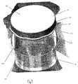
- the result is the petaloid structure of Fig.8, in which reformed areas 22 alternate with plain areas 23 around the circumference of the skirt 14.
- the crown closure 12 may be removed from the bottle 11 using a conventional bottle opener.
- the plain areas 23 provide particularly good sites on which the bottle opener can be employed.
- Figs. 9 & 10 show an alternative crown closure having a centre panel 13, peripheral skirt 14 and sealing compound 16 etc. as previously described.
- the skirt 14 is flared outwardly and the curl at the end thereof is an inwardly facing curl 24.
- the closure 12 is placed on a bottle 11 as before, and presented to apparatus as previously described with reference to Figs. 1 to 4.
- the capping tool moves downwardly reforming the skirt 14 into the position shown in Fig.10, in which the inner curl 24 is rolled under the capping bead 18 on the bottle 11, securing the crown closure on to the bottle as previously described.
Landscapes
- Engineering & Computer Science (AREA)
- Mechanical Engineering (AREA)
- Sealing Of Jars (AREA)
Abstract
A bottle (11) is capped with a metallic crown
closure (12) having a centre panel (13), a peripheral
skirt (14) and a curl portion (15) at the edge thereof.
A capping tool (2) moves the curl (15) under a capping
bead (18) on the bottle, to attach the closure thereto.
The curl (15) is typically an outwardly facing curl which
is partially unrolled by the capping tool (2) as it moves
the curl under the capping bead (18). Thus the curl may
be provided with more than 360° of material when viewed
in cross section, so that there is at least 270° of
material after the curl has been moved under the capping
bead (18).
Description
- The present invention relates to the capping of bottles, and in particular to the use of crown closures. Such closures are long established for the capping of glass and, more recently, plastics bottles. They traditionally consist of a top panel lined with a sealing compound, and a peripheral skirt which is crimped onto the bottle to close it. The closure is removed with a traditional bottle opener, or in some cases can be twisted off of a threaded finish on the bottle.
- The present invention seeks to provide an improved method for the capping of bottles, and an improved closure for use therein.
- Accordingly there is provided a method of capping a bottle comprising the steps of:
- i) providing a metallic crown closure including a centre panel, and a peripheral skirt portion depending downwardly therefrom, the distal end of the skirt portion being curled to form a curl portion;
- ii) locating the crown closure over the neck of a bottle, the neck of the bottle including an outwardly extending capping bead; and
- iii) reforming of the crown closure to move at least a part of the curl portion under the capping bead, thereby securing the crown closure onto the neck of the bottle.
-
- The above method results in a bottle closed with a crown closure which creates a distinctive appearance. Furthermore, the curl portion serves to maintain the cut edge of the metallic closure away from the surface of the bottle. Thus, even if rust starts to form on the edge of the closure, e.g in hot and humid climates such as the Far East, this rust is not deposited on to the bottle surface when the closure is removed.
- The crown closure is preferably provided with an outwardly facing curl portion, and preferably also comprising more than 360° of material when viewed in cross section. Typically the reforming step acts to roll the curl portion downwardly with respect to the centre panel. The curl portion is partially unrolled during the reforming operation as it is moved under the capping bead. Preferably the reforming step acts to roll the curl portion such that there is still more than 270°, and preferably 360° of material when viewed in cross section, after the curl portion has been moved under the capping bead. Optionally the reforming step also acts to tighten the curl portion as it is moved.
- According to one arrangement, the reforming step moves the entire curl portion under the capping bead. The method preferably includes a reforming step comprising contacting the curl portion with an annular tool having a tapered infeed portion, and moving the annular tool downwardly to move the curl portion under the capping bead on the bottle. Conceivably, the tool has a generally conical shape, at least in respect of its curl contacting surface.
- Alternatively the reforming step comprises contacting the curl portion with a tool having a plurality of projections thereon, and moving the projections with respect to the curl portion so as to form a fluted arrangement in which a plurality of sections of the curl portion are moved under the capping bead of the bottle. This arrangement is particularly suited for the capping of crown closures having significantly more than 360° of material in their curl portion.
- The invention further resides in a metallic crown closure including a centre panel, and a peripheral skirt portion depending downwardly therefrom, the distal end of the skirt portion being curled outwardly to form a curl portion, the curl portion comprising more than 360° of material when viewed in cross section. The metallic crown closure is conveniently formed of aluminium, steel, or of metal coated with a polymer material.
- The invention provides a crown closure with a distinctive appearance, and significant functional advantages. For example, the curled skirt has several advantages over the conventional corrugated skirt, not least in that it provides less of a safety hazard if discarded inappropriately. Furthermore, the uncurled corrugated crown closures are prone to a problem known as 'dusting', in which closures contact each other during transit and the sharp edges of the crown closures chip off small particles of coating materials, producing dust particles which can cause contamination. The curled periphery of the crown closures of the present invention help to avoid this problem.
- It is conceivable that the use of a curled portion which on application is moved under the capping bead, may allow the use of thinner material. The curl adds strength to the closure, giving an opportunity for lightweighting. Another possible advantage is that, by providing a relatively plain skirt portion as opposed to the corrugated skirts used previously, the skirt portion may be used for printing decorative or promotional material.
- The invention will now be further described by way of example only, with reference to the accompanying drawings, in which:-
- Fig.1 is a schematic sectional view of capping apparatus for carrying out the method of the present invention, shown in a first position;
- Fig.2 is a schematic sectional view of the apparatus of Fig.1, shown in a second position;
- Fig.3 is an enlarged view of a part of Fig.1;
- Fig.4 is an enlarged view of a part of Fig.2;
- Fig.5 is a schematic sectional view of apparatus for carrying out an alternative embodiment of the invention;
- Fig.6 is a perspective view of a capping tool for use in the apparatus of Fig.5;
- Fig.7 is a schematic sectional view of the apparatus of Fig.5, shown in a second position;
- Fig.8 is a perspective view of a crown closure affixed to a bottle using the apparatus of Figs.5 - 7;
- Fig.9 is a schematic sectional view of an alternative embodiment of the crown closure for use in accordance with the apparatus of Figs. 1 to 4; and
- Fig.10 is a schematic sectional view of the closure of Fig.9, shown after it has been sealed on to a bottle.
-
- Referring to Fig.1, capping apparatus shown generally at 1 comprises a
capping tool 2 reciprocal on acentral shaft 3. The capping tool is generally cup shaped and comprises acylindrical sidewall 4 depending from an upper end 5. Acentral hole 6 allows theshaft 3 to pass therethrough. The lower end of the tool is open, theopening 7 being provided with a tapered infeedsection 8. Theshaft 3 has apiston plate 9 at the lower end thereof and aspring 10 is constrained between the piston plate and the upper end 5 of the tool. - A bottle shown generally at 11 is presented to the apparatus 1, with a
crown closure 12 placed thereon. The crown closure comprises acentre panel 13 and aperipheral skirt 14 depending therefrom. Theskirt 14 terminates in anouter curl 15 which, as shown in Fig.3, comprises a complete curl including at least 360° of material. A gasket ofsealing compound 16, typically a plastisol material, is attached to the underside of the centre panel between the panel and anannular top surface 17 of the bottle. The bottle also includes anannular capping bead 18, and theouter curl 15 lies adjacent thecapping bead 18. - To attach the
crown closure 12 to the bottle 11, thepiston plate 9 holds the closure in position, and thecapping tool 2 is lowered on the central shaft from the position shown in Figs.1 and 3 to that shown in Figs. 2 and 4. As thecapping tool 2 is lowered, the tapered infeedsection 8 progressively contacts theouter curl 15, moving it downwardly and inwardly to the position shown in Fig.4, in which it lies under thecapping bead 18. During this movement theouter curl 15 is partially uncurled, but remains curled to the extent that at least 270° of material is contained within the curl. In this way thecrown closure 12 is attached to the bottle 11 having a distinctive slimline appearance. Furthermore, thecut edge 19 of the closure is hidden so as not to pose a danger to users, and yet it is also maintained in a position away from the surface of the bottle so that if rust starts to form on thecut edge 19, it is not in contact with the bottle 11. - Figs.5 to 7 show an alternative embodiment of apparatus in which features similar to those in Figs. 1 to 4 are designated with like reference numerals. The apparatus is suitable for capping
crown closures 12 in which theouter curl 15 is provided with substantially more than one turn of material, in this case approximately 1½ turns of metal. Thecapping tool 2 differs from that described previously in that the tapered infeedsection 8 is castellated, and has inwardly extendingsegments 20 separated byland portions 21. This tool is shown in Fig.6. - The operation of the apparatus is similar to that previously described, with the
capping tool 2 being lowered on thecentral shaft 3 as shown in Fig.7. Thesegments 20 contact theouter curl 15 so as to urge it under thecapping bead 18 at those positions around its circumference in which contact is made. The result is the petaloid structure of Fig.8, in which reformedareas 22 alternate withplain areas 23 around the circumference of theskirt 14. - In both of the above embodiments, the
crown closure 12 may be removed from the bottle 11 using a conventional bottle opener. In the arrangement of Fig.8, theplain areas 23 provide particularly good sites on which the bottle opener can be employed. - Figs. 9 & 10 show an alternative crown closure having a
centre panel 13,peripheral skirt 14 and sealingcompound 16 etc. as previously described. In the closure of Figs. 9 & 10, however, theskirt 14 is flared outwardly and the curl at the end thereof is an inwardly facingcurl 24. Theclosure 12 is placed on a bottle 11 as before, and presented to apparatus as previously described with reference to Figs. 1 to 4. The capping tool moves downwardly reforming theskirt 14 into the position shown in Fig.10, in which theinner curl 24 is rolled under the cappingbead 18 on the bottle 11, securing the crown closure on to the bottle as previously described.
Claims (15)
- A method of capping a bottle comprising the steps of:i) providing a metallic crown closure including a centre panel, and a peripheral skirt portion depending downwardly therefrom, the distal end of the skirt portion being curled to form a curl portion;ii) locating the crown closure over the neck of a bottle, the neck of the bottle including an outwardly extending capping bead; andiii) reforming of the crown closure to move at least a part of the curl portion under the capping bead, thereby securing the crown closure onto the neck of the bottle.
- A method according to claim 1, characterised in that the crown closure is provided with an outwardly facing curl portion.
- A method according to claim 1 or claim 2, characterised in that the crown closure is provided with a curl portion comprising more than 360° of material when viewed in cross section.
- A method according to any of claims 1 to 3, characterised in that the reforming step acts to roll the curl portion downwardly with respect to the centre panel.
- A method according to claim 4, characterised in that the reforming step acts to tighten the curl portion as it is moved.
- A method according to claim 4 or claim 5, characterised in that the reforming step acts to roll the curl portion such that there is still more than 270° of material when viewed in cross section, after the curl portion has been moved under the capping bead.
- A method according to any preceding claim, characterised in that the reforming step moves the entire curl portion under the capping bead.
- A method according to claim 7, characterised in that the reforming step comprises contacting the curl portion with an annular tool having a tapered infeed portion, and moving the annular tool downwardly to move the curl portion under the capping bead on the bottle.
- A method according to any of claims 1 to 6, characterised in that the reforming step comprises contacting the curl portion with a tool having a plurality of projections thereon, and moving the projections with respect to the curl portion so as to form a fluted arrangement in which a plurality of sections of the curl portion are moved under the capping bead of the bottle.
- A metallic crown closure for use in the method of any of claims 1 to 9.
- A metallic crown closure including a centre panel, and a peripheral skirt portion depending downwardly therefrom, the distal end of the skirt portion being curled to form a curl portion, the curl portion comprising more than 360° of material when viewed in cross section.
- A metallic crown closure according to claim 11, characterised in that the curl portion is an outwardly facing curl portion.
- A metallic crown closure according to claim 11 or 12, characterised in that it is formed of aluminium.
- A metallic crown closure according to claim 11 or 12, characterised in that it is formed of steel.
- A metallic crown closure according to claim 13 or claim 14, characterised in that it is formed of metal coated with a polymer material.
Priority Applications (1)
| Application Number | Priority Date | Filing Date | Title |
|---|---|---|---|
| EP00305589A EP1170246A1 (en) | 2000-07-03 | 2000-07-03 | Capping of bottles |
Applications Claiming Priority (1)
| Application Number | Priority Date | Filing Date | Title |
|---|---|---|---|
| EP00305589A EP1170246A1 (en) | 2000-07-03 | 2000-07-03 | Capping of bottles |
Publications (1)
| Publication Number | Publication Date |
|---|---|
| EP1170246A1 true EP1170246A1 (en) | 2002-01-09 |
Family
ID=8173096
Family Applications (1)
| Application Number | Title | Priority Date | Filing Date |
|---|---|---|---|
| EP00305589A Withdrawn EP1170246A1 (en) | 2000-07-03 | 2000-07-03 | Capping of bottles |
Country Status (1)
| Country | Link |
|---|---|
| EP (1) | EP1170246A1 (en) |
Cited By (5)
| Publication number | Priority date | Publication date | Assignee | Title |
|---|---|---|---|---|
| WO2005118398A1 (en) | 2004-06-02 | 2005-12-15 | Shikoku Kakoki Co., Ltd. | Filling/packaging machine |
| CN103626093A (en) * | 2013-11-18 | 2014-03-12 | 江苏华宇飞凌包装机械有限公司 | Glass bottle screwing cap capping die adjustable in pressure |
| JP2016190648A (en) * | 2015-03-31 | 2016-11-10 | 日本クロージャー株式会社 | Method and device for mounting container lid on neck of container |
| IT201900003503A1 (en) | 2019-03-11 | 2020-09-11 | Sacmi | CLOSURE FOR CONTAINERS |
| CN112551461A (en) * | 2019-09-25 | 2021-03-26 | 佩里科尼股份公司 | Capping head, system and method |
Citations (4)
| Publication number | Priority date | Publication date | Assignee | Title |
|---|---|---|---|---|
| FR812508A (en) * | 1936-10-24 | 1937-05-12 | New metal capsule; method and apparatus for attaching it to a bottle or the like | |
| CH473003A (en) * | 1966-08-29 | 1969-05-31 | Hunter Thomas Ltd | Method for attaching a closure lid to a container, container manufactured according to the method with closure lid and device for carrying out the method |
| US3633781A (en) * | 1968-12-16 | 1972-01-11 | Lapata Ind Inc | Crown-type closure with double removable liner unit enclosing trapped indicia |
| DE2926675A1 (en) * | 1978-09-04 | 1980-03-13 | Cerveceria Cuauhtemoc S A | Cap for fragile containers - has cylindrical projection ends in circumferential flange held in bottom part |
-
2000
- 2000-07-03 EP EP00305589A patent/EP1170246A1/en not_active Withdrawn
Patent Citations (4)
| Publication number | Priority date | Publication date | Assignee | Title |
|---|---|---|---|---|
| FR812508A (en) * | 1936-10-24 | 1937-05-12 | New metal capsule; method and apparatus for attaching it to a bottle or the like | |
| CH473003A (en) * | 1966-08-29 | 1969-05-31 | Hunter Thomas Ltd | Method for attaching a closure lid to a container, container manufactured according to the method with closure lid and device for carrying out the method |
| US3633781A (en) * | 1968-12-16 | 1972-01-11 | Lapata Ind Inc | Crown-type closure with double removable liner unit enclosing trapped indicia |
| DE2926675A1 (en) * | 1978-09-04 | 1980-03-13 | Cerveceria Cuauhtemoc S A | Cap for fragile containers - has cylindrical projection ends in circumferential flange held in bottom part |
Cited By (8)
| Publication number | Priority date | Publication date | Assignee | Title |
|---|---|---|---|---|
| WO2005118398A1 (en) | 2004-06-02 | 2005-12-15 | Shikoku Kakoki Co., Ltd. | Filling/packaging machine |
| EP1759996A4 (en) * | 2004-06-02 | 2012-11-21 | Shikoku Kakoki Co Ltd | FILLING / PACKING MACHINE |
| CN103626093A (en) * | 2013-11-18 | 2014-03-12 | 江苏华宇飞凌包装机械有限公司 | Glass bottle screwing cap capping die adjustable in pressure |
| CN103626093B (en) * | 2013-11-18 | 2015-12-23 | 江苏华宇飞凌包装机械有限公司 | The Die for pressing cap of glass bottle spiral cover pressure adjustable |
| JP2016190648A (en) * | 2015-03-31 | 2016-11-10 | 日本クロージャー株式会社 | Method and device for mounting container lid on neck of container |
| IT201900003503A1 (en) | 2019-03-11 | 2020-09-11 | Sacmi | CLOSURE FOR CONTAINERS |
| CN112551461A (en) * | 2019-09-25 | 2021-03-26 | 佩里科尼股份公司 | Capping head, system and method |
| CN112551461B (en) * | 2019-09-25 | 2024-05-03 | 佩里科尼股份公司 | Capping head, system and method |
Similar Documents
| Publication | Publication Date | Title |
|---|---|---|
| EP1238917A1 (en) | Crown closure with curled lower edge | |
| EP2746184B1 (en) | Low gauge crown cap | |
| US6779677B2 (en) | Aluminum receptacle with threaded outsert | |
| US3281001A (en) | Crown cap | |
| EP1500598B1 (en) | Opening curled part of metal container and method of forming the opening curled part | |
| US20100003109A1 (en) | Method for producing such a metal closure with seperate disc and ring from a single closure blank | |
| CN107567359B (en) | Ringless metal can and method | |
| US4823537A (en) | Method of forming a pilferproof closure | |
| CA2075437A1 (en) | Container with curled tamper-evident band to retain closure | |
| CA1180685A (en) | Closure cap and method of making | |
| EP0096582A2 (en) | Composite closure | |
| EP2011737B1 (en) | Can container | |
| WO2014060800A2 (en) | Second generation low gauge crown cap | |
| US1956217A (en) | Container closure | |
| US20240327075A1 (en) | Bottle Cap | |
| US4679697A (en) | Bottle top | |
| GB1588105A (en) | Method and apparatus for applying closures to containers | |
| AU3015800A (en) | Lined closure for containers of differing finish configurations | |
| CA1244360A (en) | Container finish for resealing with pt closure | |
| GB2103174A (en) | Easy open can end | |
| CA2174039A1 (en) | Smooth edge twist crown closure |
Legal Events
| Date | Code | Title | Description |
|---|---|---|---|
| PUAI | Public reference made under article 153(3) epc to a published international application that has entered the european phase |
Free format text: ORIGINAL CODE: 0009012 |
|
| AK | Designated contracting states |
Kind code of ref document: A1 Designated state(s): AT BE CH CY DE DK ES FI FR GB GR IE IT LI LU MC NL PT SE |
|
| AX | Request for extension of the european patent |
Free format text: AL;LT;LV;MK;RO;SI |
|
| STAA | Information on the status of an ep patent application or granted ep patent |
Free format text: STATUS: THE APPLICATION IS DEEMED TO BE WITHDRAWN |
|
| 18D | Application deemed to be withdrawn |
Effective date: 20011114 |