EP1170101A1 - Barrique de bois, son procédé de fabrication et dispositif pour sa mise en oeuvre - Google Patents
Barrique de bois, son procédé de fabrication et dispositif pour sa mise en oeuvre Download PDFInfo
- Publication number
- EP1170101A1 EP1170101A1 EP01401072A EP01401072A EP1170101A1 EP 1170101 A1 EP1170101 A1 EP 1170101A1 EP 01401072 A EP01401072 A EP 01401072A EP 01401072 A EP01401072 A EP 01401072A EP 1170101 A1 EP1170101 A1 EP 1170101A1
- Authority
- EP
- European Patent Office
- Prior art keywords
- slats
- profile
- faces
- barrel
- slat
- Prior art date
- Legal status (The legal status is an assumption and is not a legal conclusion. Google has not performed a legal analysis and makes no representation as to the accuracy of the status listed.)
- Granted
Links
- 238000004519 manufacturing process Methods 0.000 title claims description 14
- 238000000034 method Methods 0.000 title claims description 9
- 230000000295 complement effect Effects 0.000 claims abstract description 22
- 238000003825 pressing Methods 0.000 claims description 15
- 238000003754 machining Methods 0.000 claims description 13
- 238000005520 cutting process Methods 0.000 claims description 5
- 235000015096 spirit Nutrition 0.000 claims description 3
- 230000003213 activating effect Effects 0.000 claims 1
- 235000015115 caffè latte Nutrition 0.000 description 20
- 241000219492 Quercus Species 0.000 description 11
- 230000000712 assembly Effects 0.000 description 5
- 238000000429 assembly Methods 0.000 description 5
- 239000002023 wood Substances 0.000 description 5
- 241000220479 Acacia Species 0.000 description 4
- 235000010643 Leucaena leucocephala Nutrition 0.000 description 4
- 238000007789 sealing Methods 0.000 description 4
- 239000007788 liquid Substances 0.000 description 3
- 238000011144 upstream manufacturing Methods 0.000 description 3
- 241000735470 Juncus Species 0.000 description 2
- 230000004075 alteration Effects 0.000 description 2
- 230000006837 decompression Effects 0.000 description 2
- 238000005304 joining Methods 0.000 description 2
- 241001644893 Entandrophragma utile Species 0.000 description 1
- LFQSCWFLJHTTHZ-UHFFFAOYSA-N Ethanol Chemical compound CCO LFQSCWFLJHTTHZ-UHFFFAOYSA-N 0.000 description 1
- 229920002522 Wood fibre Polymers 0.000 description 1
- 230000004913 activation Effects 0.000 description 1
- 239000000853 adhesive Substances 0.000 description 1
- 230000001070 adhesive effect Effects 0.000 description 1
- 230000032683 aging Effects 0.000 description 1
- 238000004891 communication Methods 0.000 description 1
- 238000010586 diagram Methods 0.000 description 1
- 230000000694 effects Effects 0.000 description 1
- 239000012467 final product Substances 0.000 description 1
- 235000013305 food Nutrition 0.000 description 1
- 239000003292 glue Substances 0.000 description 1
- 238000002955 isolation Methods 0.000 description 1
- 239000002184 metal Substances 0.000 description 1
- 230000000813 microbial effect Effects 0.000 description 1
- 210000000056 organ Anatomy 0.000 description 1
- 239000000047 product Substances 0.000 description 1
- 241000894007 species Species 0.000 description 1
- 239000000126 substance Substances 0.000 description 1
- 230000008961 swelling Effects 0.000 description 1
- 239000002025 wood fiber Substances 0.000 description 1
Images


Classifications
-
- B—PERFORMING OPERATIONS; TRANSPORTING
- B27—WORKING OR PRESERVING WOOD OR SIMILAR MATERIAL; NAILING OR STAPLING MACHINES IN GENERAL
- B27H—BENDING WOOD OR SIMILAR MATERIAL; COOPERAGE; MAKING WHEELS FROM WOOD OR SIMILAR MATERIAL
- B27H3/00—Manufacture of constructional elements of tubes, coops, or barrels
- B27H3/04—Manufacture of barrel heads or casings
-
- B—PERFORMING OPERATIONS; TRANSPORTING
- B27—WORKING OR PRESERVING WOOD OR SIMILAR MATERIAL; NAILING OR STAPLING MACHINES IN GENERAL
- B27H—BENDING WOOD OR SIMILAR MATERIAL; COOPERAGE; MAKING WHEELS FROM WOOD OR SIMILAR MATERIAL
- B27H5/00—Manufacture of tubes, coops, or barrels
-
- B—PERFORMING OPERATIONS; TRANSPORTING
- B27—WORKING OR PRESERVING WOOD OR SIMILAR MATERIAL; NAILING OR STAPLING MACHINES IN GENERAL
- B27M—WORKING OF WOOD NOT PROVIDED FOR IN SUBCLASSES B27B - B27L; MANUFACTURE OF SPECIFIC WOODEN ARTICLES
- B27M3/00—Manufacture or reconditioning of specific semi-finished or finished articles
- B27M3/0013—Manufacture or reconditioning of specific semi-finished or finished articles of composite or compound articles
- B27M3/0066—Manufacture or reconditioning of specific semi-finished or finished articles of composite or compound articles characterised by tongue and groove or tap hole connections
-
- B—PERFORMING OPERATIONS; TRANSPORTING
- B65—CONVEYING; PACKING; STORING; HANDLING THIN OR FILAMENTARY MATERIAL
- B65D—CONTAINERS FOR STORAGE OR TRANSPORT OF ARTICLES OR MATERIALS, e.g. BAGS, BARRELS, BOTTLES, BOXES, CANS, CARTONS, CRATES, DRUMS, JARS, TANKS, HOPPERS, FORWARDING CONTAINERS; ACCESSORIES, CLOSURES, OR FITTINGS THEREFOR; PACKAGING ELEMENTS; PACKAGES
- B65D9/00—Containers having bodies formed by interconnecting or uniting two or more rigid, or substantially rigid, components made wholly or mainly of wood or substitutes therefor
- B65D9/02—Containers of curved cross-section, e.g. cylindrical boxes
- B65D9/04—Containers of curved cross-section, e.g. cylindrical boxes made up of staves, e.g. barrels for liquids
-
- Y—GENERAL TAGGING OF NEW TECHNOLOGICAL DEVELOPMENTS; GENERAL TAGGING OF CROSS-SECTIONAL TECHNOLOGIES SPANNING OVER SEVERAL SECTIONS OF THE IPC; TECHNICAL SUBJECTS COVERED BY FORMER USPC CROSS-REFERENCE ART COLLECTIONS [XRACs] AND DIGESTS
- Y02—TECHNOLOGIES OR APPLICATIONS FOR MITIGATION OR ADAPTATION AGAINST CLIMATE CHANGE
- Y02A—TECHNOLOGIES FOR ADAPTATION TO CLIMATE CHANGE
- Y02A40/00—Adaptation technologies in agriculture, forestry, livestock or agroalimentary production
- Y02A40/90—Adaptation technologies in agriculture, forestry, livestock or agroalimentary production in food processing or handling, e.g. food conservation
Definitions
- the present invention relates to a wooden barrel particularly for the production of wine and spirits, a process of manufacture of a base for such a barrel, and a device for the implementation of such a method.
- a barrel typically has a body in the form of curved cylinder closed at its two ends by two bottoms of barrel, also in oak wood. Such a background must satisfy essentially two criteria, watertightness and the ability to withstand pressure of two bars on its inner face.
- the object of the present invention is to provide such wooden barrel, the bottom of which is cheaper to produce, due to the absence of acacia studs and sealing rod in its manufacturing. Another object is to increase the solidity and / or the tightness by compared to a background obtained by the traditional method described above.
- the invention relates to a wooden barrel in particular for the production of wine and spirits, comprising a body closed by two bottoms, each barrel bottom comprising a set of substantially straight slats of cross section substantially rectangular assembled parallel to each other by opposite side faces, characterized in that the two adjacent side faces of two of said assembled slats are in substantially sealed contact, said two lateral faces having in a plane perpendicular to the longitudinal direction of said slats two substantially complementary longitudinal profiles able to be press fit into each other, a first of said profiles comprising a first part inclined relative to the direction of thickness of said slats and a first female part extending towards the inside of the thickness of the slat in its transverse direction, and the second of said profiles comprising a second part inclined by relative to the thickness direction of the slat substantially parallel to said first inclined part and a second male part substantially complementary to said first female part.
- each female part forms a groove rectangular, the bottom of which is substantially parallel to said direction thick.
- said first profile includes a first male part extending towards the outside of the slat in its direction transverse, and the second profile has a second female part substantially complementary.
- said first profile has successively from one of its ends said first part inclined, said first male part and said first female part.
- said first profile has a third inclined portion extending from said first male part, said third inclined part being inclined to the thickness direction of the slat and ending at the other end of said first profile, and the second profile has a fourth inclined part substantially complementary to said third part inclined.
- said first and third parts inclined of said first profile are substantially parallel to each other.
- said first profile has a longitudinal axis of symmetry located halfway along the profile section connecting the bottom of said first female part to the top of said first male part.
- each inclined part makes an angle of about 30 degrees from said thickness direction.
- said machining step allows machining simultaneous said two opposite side faces of said slat using at least two separate or identical cutting tools.
- said nesting step comprises successively the arrangement of said batch of slats to be assembled by their useful surfaces on a support surface, the positioning of a holding member for exerting pressure on the free working face of all the slats of said batch in the direction of said support surface, and activation of at least one movable pressing member substantially perpendicular to said side faces, between said surface of support and said holding member.
- Another object of the present invention is a device for the implementation of the process described above, characterized by fact that it includes a press for performing said nesting step, said press comprising said support surface for supporting the pressing parts, said holding member which comprises a surface for substantially flat support at one of its ends and is capable of exerting pressure from said holding surface towards said surface of support, and said at least one pressing member located near a end of said support surface, each pressing member having a bearing face and being capable of exerting a force to moving said bearing face in a direction parallel to said surface support, said holding member being movable between a position handling in which said holding surface is offset by relative to said support surface and a holding position in which said retaining surface covers at least part central of said support surface.
- said press comprises two organs of pressing whose bearing faces are arranged face to face on the side and on the other of said central part of the support surface.
- said holding member comprises an arm movable in rotation about an axis located at one end of said support surface, a free end of said arm carrying said surface holding.
- the barrel according to the invention generally comprises a body (not shown) substantially in the shape of a curved cylinder, with a central part with a diameter greater than that of its ends, closed at the said ends by two cut wooden barrel bottoms disc-shaped.
- the bottom 1 of the barrel according to the invention visible in FIG. 3, comprises a set of oak wooden slats 2, called bottom pieces, which are assembled parallel to each other to others by force fitting by their side faces 3.
- the manufacturing method according to the invention includes a step where a lot 4 of bottom pieces 2 is selected, so that the length and width of the meeting of the slats 2 of lot 4 are sufficient for a barrel base to be cut there later, after assembly of the slats 2.
- Lot 4 includes several slats 2 of different lengths and widths, arranged parallel to each other, the slats 2 of greater length being preferably arranged in the middle of lot 4.
- a slat 2 a for example, a thickness of around 25 mm, a width of around 4 to 13 cm and a length of the order of 45 to 85 cm.
- the longitudinal direction A of the bottom pieces 2 is generally parallel wood fibers.
- the lateral assembly faces 3 of the slats 2 of the batch 4 carry a profile which has been previously machined there, and which will be described lower, able to allow their assembly by force fitting and self-tightening.
- the useful faces 5 and 15 of the slats 2 are regular and noticeably flat.
- the slats 2 of a lot 4 are then forced into place by their side faces 3.
- the step fitting 2 using a clamping press will be described below.
- the assembly of slats 6, visible at the Figure 2 shows a useful face 5 substantially planar and sealed.
- the next step is to cut into assembly 6 a disc, for example with a diameter of about 50 cm, to form the barrel bottom 1, visible in Figure 3.
- each slat 2 of the assembly 6 is fitted by their side faces 3.
- the side faces of which 7 are not necessarily machined each slat 2 of the assembly 6 has its two lateral faces 3 machined according to two profiles transverse 8 and 9, complementary to each other, invariant in the longitudinal direction A of the slats 2.
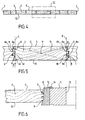
- the transverse profile 8 of a lateral assembly face 3 of a batten 2 successively comprises in the thickness direction E of the slat to from the useful face 5: an inclined part 8a, with an angle of substantially 30 ° for example, towards the inside of the slat 2 relative to to said thickness direction E, a male part, in the form of a tongue with rectangular section 8b with apex parallel to said direction of thickness E, a female part, in the form of a section groove rectangular bottom 8c parallel to said thickness direction E, and a part 8d inclined towards the outside of the slat 2 at an angle with respect to said thickness direction E to the useful face opposite 15.
- the rectangular section tab 8b and the groove at rectangular section 8c are substantially the same width, substantially equal to 4.4 mm for example.
- the transverse profile 9 is complementary to the profile transverse 8 and comprises successively, in said direction of thickness E of the batten, from the same useful face 5: a part 9a inclined at the same angle, for example substantially 30 °, towards the outside of the slat 2 relative to said thickness direction E, a female part, in the form of a groove with rectangular section 9b at the bottom parallel to said thickness direction E of the slat 2, a male part, tongue-shaped rectangular section 9c with apex parallel to said thickness direction E of the slat 2, and an inclined part 9d of the same angle, of substantially 30 ° for example, towards the inside of the batten 2 with respect to said thickness direction E.
- edges transversely external with respect to the slat 2 of the parts 8a and 8d of profile 8 are substantially aligned with the top of the tongue 8b (respectively 9c).
- the transversely internal edges with respect to to the slat 2 of the inclined parts 8a and 8d of the profile 8 are substantially aligned with the bottom of the groove 8c (respectively 9b).
- the profile 8 of a side face 3 is fitted in profile 9 of side face 3 adjacent to the neighboring slat, the inclined parts 8a and 9a are in contact, the tongue 8b is engaged in the groove 9b, the tongue 9c is engaged in the groove 8c, and the inclined parts 8d and 9d are in contact.
- the assembly 6 is maintained by self-tightening, it does not include no glue, stud, or other means of attachment. Contact between adjacent assembly side faces 3 is substantially sealed. The swelling of the wood can further improve the sealing of assembly 6.
- the angles and are substantially equal, so that the parts of the profile 8 inclined inwards and outwards respectively 8a and 8d are substantially parallel.
- the 8th segment joining the bottom of the groove 8c at the top of the tongue 8b is located substantially at the half the thickness of the slat, and the longitudinal axis passing through the midpoint C of this segment 8e is substantially axis of symmetry of the transverse profile 8.
- the complementary transverse profiles 8 and 9 are the image of each other by a central symmetry.
- Each slat 2 can then have a central symmetry with respect to an axis longitudinal median passing through point M located at the intersection of diagonals D of a cross section of said slat, as visible at Figure 5.
- a batch 4 of slats is made from a reserve of base pieces 2 with the side faces already machined.
- the machining of the lateral assembly faces 3 can be carried out after selection of lot 4.
- the machining of lateral assembly faces 3 of a slat 2 is produced using a rotary cutting tool, comprising a mandrel 11 at the periphery from which are fixed profiled plates 12, the outer side of which mandrel 11 carries the complementary profile of the profile to be machined. So, a plate 12 for machining the profile 8 carries the profile 9, and reciprocally.
- the mandrel 11 with a profiled insert 12 has a total diameter for example of the order of 140 mm and a height in the aforementioned thickness direction E of the order of 35 mm for example. he has a central bore 13 for example of substantially 50 mm diameter, to mount it on a shaft of a rotating machine (not shown).
- An adjustment screw 14 makes it possible to adjust the position of the profiled plate 12 in the thickness direction E of the batten 2. From preferably, the machining of the two lateral faces 3 as well as the regularization of the useful faces 5 and 15 of the slat 2 is carried out in a single passage of the bottom piece 2 in a four-sided planer (not shown).
- Such a device comprises two mandrels 11 for machining simultaneously the two opposite lateral faces 3 of a slat 2. Because the symmetry of profiles 8 and 9, identical profiled plates 12 can be mounted on these two mandrels 11, the plates 12 mounted on one of said two mandrels 11 being arranged in a inverted position compared to those mounted on the other.
- the invention also relates to a clamping press to fit the bottom pieces 2 of a lot 4, visible in Figure 1, and form an assembly 6, visible in FIG. 2.
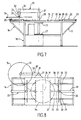
- the clamping press according to the invention will now be described, with reference to Figures 7 to 9.
- the clamping press according to the invention comprises a table metal support 16 comprising a horizontal plate 19 connected to four vertical feet 18. At each of the two ends longitudinal of the support table 16, buttresses 17 come obliquely connect the cantilever ends of said plate horizontal 19 to a horizontal link bar (not shown) joining two feet 18 to about half their height.
- the surface free plane of the plate 19 has the function of supporting a batch 4 of slats 2 to fit.
- the support table 16 has, for example, a height of about 85 cm, a length of about 225 cm and a width of around 100 cm.
- the support table 16 also carries at its ends longitudinal on both sides of the plate 19 two press members each comprising a set of piston-cylinder cylinders 22, the cylinder 23 is rigidly assembled to table 16 and the end of which free of the piston rod 20 is fixed perpendicular to a bar support 21.
- the bar 21 is also linked perpendicularly to two rods guide 24 parallel to said piston rod 20 and located on either side else of it.
- the guide rods 24 are movable in translation in guide sleeves 25 linked to table 16.
- the piston-cylinder 22 sets are double effect, to move the two grab bars 21 in both directions between a rest position close to the longitudinal end of the plate 19, this position being shown in Figure 8 in solid lines, and a pressing position close to a central part 26 of the plate 19, shown in Figure 8 in phantom.
- the piston rods 20 are substantially returned to the cylinders 23 in the rest position of the grab bars 21, and substantially extended from cylinders 23 in position for pressing the support bars 21.
- Each support bar 21 has a face support 36 substantially perpendicular to the plate 19 of length around 80 cm, so that you can press evenly over the entire length of said slats 2, the axis A of which is disposed parallel to the length of the bars 21.
- a longitudinal edge of the table 16 also has two vertically spaced 27 horizontal stirrups extending towards the outside of the table 16 substantially at mid-length thereof.
- the stirrups 27 support a vertical axis 28 which extends, for example up to about 45 cm, above the level of the plate 19, and on which a holding member 29 is rotatably mounted.
- the holding member 29 includes an arm 30 extending substantially horizontally above of table 16, linked perpendicularly to one of its ends to a tube 31 fitted on the vertical axis 28 to form a connection pivot with it and at the other end to a set of piston-cylinder 32 extending towards the table 16 substantially parallel to the vertical axis 28, including the lower free end of the piston rod 33 is linked to a rigid holding disc 34 parallel to the plate 19.
- the disc 34 is for example metallic.
- the holding member 29 is movable in rotation about the axis 28 between a handling position in which the arm 30 is substantially parallel to the longitudinal edge of the plate 19, the holding disc 34 being laterally offset by relative to the plate 19, and a holding position, in which the arm 30 is substantially perpendicular to said longitudinal edge of the table 16, the holding disc 34 being perpendicular to the central part 26 of the plate 19.
- the piston-cylinder cylinder assembly 32 is double-acting to move the holding disc 34 in both directions between, one part, a high position in which, the piston rod 33 being retracted in the cylinder 35, the holding disc 34 is located above the tray 19, for example about 15 cm, the holding member 29 can then be freely moved around its axis, and on the other hand, a low position in which the piston rod 33 having come out of the cylinder 35, the holding disc 34 is supported on the plate 19 or on the surface of the slats 2 placed on the plate 19.
- the clamping press comprises a control system which will now be described with reference to FIG. 9.
- the system 36 comprises a reservoir 37 containing a liquid at a low pressure, for example substantially equal to atmospheric pressure, for supply the system 36.
- the tank 37 has for example a capacity of 55 liters.
- the control system 36 also includes a pump 39 driven by an electric motor 40 to send high pressure liquid in a high pressure circuit 38.
- the motor 40 has for example a power of the order of 4 kW.
- the upper circuit pressure 38 passes through a calibrated non-return valve 41 and divides from a branch 42 in a first branch 45 to supply the two sets of piston-cylinder 22 through a distributor pressing 43, a second branch 46 to supply the assembly of piston-cylinder cylinder 32 through a holding distributor 44, and a third branch 47 to empty the circuit through a vacuum distributor 48.
- the high pressure circuit 38 is connected to a pressure gauge 49 through a isolation valve 50.
- the pressure gauge 49 makes it possible to control the pressure in circuit 38 in operation, which is for example equal to around 150 bar.
- System 36 also includes a low circuit pressure 51 which, starting from the reservoir 37, passes through a filter 52, and is divides into a first branch 54 which can be connected to the two sets of piston-cylinder cylinders 22 through the distributor pressing 43, a second branch 55 which can be connected to the assembly piston-cylinder cylinder 32 through the holding distributor 44, and a third branch 53 to empty the circuit by the vacuum distributor 48.
- the high pressure circuit 38 is also connected to low pressure circuit 51 to through a pressure relief valve 58 in series with a calibrated non-return valve return 59. If the pressure in the high pressure circuit 38 exceeds a prescribed safety threshold value, the pressure relief valve 58 empties directly into the tank 37.
- the vacuum distributor 48 has two positions: a vacuum position, shown in Figure 9, in which it connects the third branch 47 of the circuit high pressure 38 with the third branch 53 of the low pressure circuit 51, so that the high pressure circuit 38 can be emptied into the reservoir 37 until it is at the same pressure as the latter; and an pressurized position in which it obstructs the third branch 47 of the high pressure circuit 38, so that a high pressure greater than that of the liquid stored in the reservoir 37 can be established in circuit 38.
- the vacuum distributor 48 includes an electromechanical control 57 to actuate it in its position pressurizing and a return spring 56 which exerts a force to return it to its vacuum position.
- the distributor 48 can thus fulfill a general switch function of the system 36, its vacuum position corresponding to a system shutdown state 36 and its pressurizing position corresponding to a state system ignition 36.
- supply 60 and 61 of the piston-cylinder 22 sets are linked the two compartments of the cylinders 23 respectively.
- supply 60 is divided into two branches 60a and 60b linked respectively to the compartment of each of the two cylinders 23 outside relative to the plate 19.
- the supply line 61 is divides into two branches 61a and 61b linked respectively to compartment of each of the two cylinders 23 inside relative to the tray 19.
- the two branches 60a and 60b pass through a divider of flow 62, which imposes an equal flow in each of them, so that the piston rods 20 of the two sets of piston-cylinder cylinder 22 can only move together and at the same distance, both in the direction of tightening and in the direction of loosening.
- the supply line 60 is connected to a pressure limiter 63, which allows the pipe supply 60 to empty if the pressure there exceeds a value of prescribed operating threshold. It therefore adjusts the pressure maximum operating in line 60 during tightening.
- the movements of the pistons of the cylinder assemblies piston-cylinder 22 are controlled by the distributor 43 which comprises three positions: a stop position in which the two lines 60 and 61 are blocked, so that the pistons of the piston-cylinder cylinder assemblies 22 are immobilized; a position clamp in which the supply line 60 is connected to the branch 45 of the high pressure circuit and the supply line 61 is connected to branch 54 of the low pressure circuit, so that the rods piston 20 are moved in the direction of pressing towards the center of the plate 19; and a release position in which the pipe supply 60 is connected to branch 54 of the low pressure circuit and the supply line 61 is connected to the branch 45 of the upper circuit pressure, so that the piston rods 20 are moved in the direction loosening towards the ends of the plate 19.
- the distributor 43 has two electromechanical controls 65 to move it respectively towards its clamping position and its loosening position, against two return springs 66 whose effort is exerted to return the distributor 43 to its central position, which is its position Stop.
- two supply lines 67 and 68 of the piston-cylinder cylinder assembly 32 are linked respectively to the upper and lower compartments of the cylinder 35.
- the supply line 67 is connected to a pressure relief valve 69, which allows it to empty if the pressure exceeds a value operating threshold. It therefore adjusts the maximum operating pressure in line 67 when tightening of the holding disc 34 in the low position.
- the movements of the piston-cylinder cylinder assembly 32 are controlled by the distributor 44 which also includes three positions: a decompression position in which both supply lines 67 and 68 are put in communication with the branch 55 of the low pressure circuit so as to decompress them, so that the piston in the piston-cylinder cylinder assembly 32 can then be freely moved in the cylinder 35; a position of tightening in which the supply line 67 is connected to the branch 46 of the high pressure circuit and the supply line 68 is connected to branch 55 of the low pressure circuit, so that the rod piston 33 is moved in the pressing direction, in which the disc holding 34 is moved to the plate 19; and a position of loosening in which the supply line 67 is connected to the branch 55 of the low pressure circuit and the supply line 68 is connected to branch 46 of the high pressure circuit, so that the rod piston 33 is moved in the loosening direction, in which the disc holding 34 is moved to its upper position.
- Distributor 44 has two electromechanical controls 70 for moving it respectively towards its clamping position and its loosening position, against two return
- the hydraulic control system 36 allows independently control the movements of the cylinder assembly to piston-cylinder 32 via the distributor 44, and the movements of the two sets of piston-cylinder cylinder 22, by through the independent distributor 43, in order to carry out the step fitting described below.
- the step of fitting the slats 2 takes place in the manner next.
- the holding member 29 is in the position of handling, the holding disc 34 being in the high position.
- the grab bars 21 are in the rest position, close to the ends longitudinal of the plate 19.
- the vacuum distributor 48 is positioned in pressurized position to allow use of the press.
- the bottom pieces 2 of a lot 4 with their two faces side 3 previously machined in accordance with the description above, are extended by hand on the central part 26 of the plate 19, in the order in which they must be assembled, their faces lateral assembly 3 parallel to the bearing faces 36 of the bars 21.
- the holding member 29 is then brought into the position of holding with the holding disc 34 plumb with the slats 2 to to assemble.
- the distributor 44 being actuated in the clamping position, the piston-cylinder cylinder assembly 32 causes the lowering of the disc 34 until exerting a holding pressure on the useful face free of the slats 2.
- the distributor 43 then being actuated also in clamping position, piston-cylinder cylinder assemblies 22 cause the support bars 21 to move towards their position of Tightening. The support bars 21 move until they come into contact with the outer lateral faces 7 of the set of slats 2 and exert a pressure which causes the interlocking of the side faces 3 adjacent slats 2.
- the support bars 21 have a lower height to the thickness of the slats 2, in order to be able to pass under the disc of hold during tightening, as visible in phantom in Figure 8.
- the holding disc 34 must also exert sufficient holding pressure to prevent these to shift vertically.
- the distributor 43 When the fitting is completed, the distributor 43 is brought to the release position and the piston-cylinder actuator assemblies 22 are thus actuated to bring back the support bars 21 towards their rest position.
- the distributor 44 is in turn brought in loosening position and the cylinder-piston cylinder assembly 32 is actuated to raise the disc 34.
- the holding member 29 can then be returned to its handling position to allow the manual unloading of assembly 6 obtained.
- the barrel bottom 1 according to the invention can then be cut from the assembly of slats 6.
Landscapes
- Engineering & Computer Science (AREA)
- Life Sciences & Earth Sciences (AREA)
- Wood Science & Technology (AREA)
- Manufacturing & Machinery (AREA)
- Mechanical Engineering (AREA)
- Forests & Forestry (AREA)
- Automatic Assembly (AREA)
- Rigid Containers With Two Or More Constituent Elements (AREA)
- Press Drives And Press Lines (AREA)
- Optical Couplings Of Light Guides (AREA)
- Closures For Containers (AREA)
Abstract
Description
- des lattes de chêne, appelées pièces de fond, sont régularisées par usinage de leurs quatre faces (deux faces utiles, et deux faces latérales d'assemblage) ;
- elles sont ensuite triées, en fonction de leur largeur et de leur longueur, et placées les unes à côté des autres de façon à ce qu'un fond, en forme de disque, puisse y être taillé ;
- chacune des lattes de chêne est percée de deux à trois trous sur ses deux faces latérales d'assemblage, dénommées les joints ;
- des goujons en acacia sont placés dans chacun des trous d'une des faces latérales ;
- un demi-brin de jonc est disposé à plat sur chaque joint, ce qui assurera l'étanchéité entre deux pièces de fonds assemblées ;
- les lattes de chêne sont assemblées par leurs faces latérales, chaque goujon étant engagé dans deux trous en vis à vis de deux lattes pour les maintenir en emprisonnant entre elles le jonc ;
- les pièces assemblées sont ensuite taillées pour former le fond de barrique.
- la figure 1 est une vue de dessus d'un ensemble de lattes à assembler ;
- la figure 2 est une vue de dessus du même ensemble de lattes qu'à la figure 1, après assemblage ;
- la figure 3 est une vue de dessus du fond de barrique selon l'invention découpé dans l'ensemble de lattes de la figure 2 ;
- la figure 4 est une vue de côté selon la flèche IV de la figure 2 ;
- la figure 5 est un détail selon le cadre V de la figure 4 ;
- la figure 6 est une vue en coupe partielle d'un dispositif tournant pour usiner la face latérale d'une latte ;
- la figure 7 est une vue en élévation et de face d'une presse selon l'invention ;
- la figure 8 est une vue de dessus de la presse de la figure 7, dans différentes positions de fonctionnement ;
- la figure 9 est un schéma de fonctionnement du système de commande d'une presse selon l'invention.
Claims (14)
- Barrique de bois notamment pour la production de vin et d'eaux-de-vie, comportant un corps fermé par deux fonds, chaque fond de barrique (1) comportant un ensemble (6) de lattes (2) sensiblement droites de section transverse sensiblement rectangulaire assemblées parallèlement les unes aux autres par des faces latérales (3) opposées, caractérisée par le fait que les deux faces latérales (3) adjacentes de deux desdites lattes (2) assemblées sont en contact sensiblement étanche, lesdites deux faces latérales (3) présentant dans un plan perpendiculaire à la direction longitudinale (A) desdites lattes deux profils longitudinaux (8, 9) sensiblement complémentaires apte à être emboítés à force l'un dans l'autre, un premier desdits profils (8) comportant une première partie inclinée (8a) par rapport à la direction d'épaisseur (E) desdites lattes et une première partie femelle (8c) s'étendant vers l'intérieur de l'épaisseur de la latte dans sa direction transversale, et le second desdits profils (9) comportant une seconde partie inclinée (9a) par rapport à la direction d'épaisseur (E) de la latte sensiblement parallèlement à ladite première partie inclinée (8a) et une seconde partie mâle (9c) sensiblement complémentaire de ladite première partie femelle (8c).
- Barrique selon la revendication 1, caractérisée par le fait que chaque partie femelle (8c) forme une rainure rectangulaire dont le fond est sensiblement parallèle à ladite direction d'épaisseur.
- Barrique selon l'une des revendications 1 ou 2, caractérisée par le fait que ledit premier profil (8) comporte une première partie mâle (8b) s'étendant vers l'extérieur de la latte dans sa direction transversale, et le second profil (9) comporte une seconde partie femelle (9b) sensiblement complémentaire.
- Barrique selon la revendication 3, caractérisée par le fait que ledit premier profil (8) présente successivement à partir d'une de ses extrémités ladite première partie inclinée (8a), ladite première partie mâle (8b) et ladite première partie femelle (8c).
- Barrique selon la revendication 4, caractérisée par le fait que ledit premier profil (8) comporte une troisième partie inclinée (8d) s'étendant à partir de ladite première partie mâle (8c), ladite troisième partie inclinée (8d) étant inclinée par rapport à la direction d'épaisseur (E) de la latte et se terminant à l'autre extrémité dudit premier profil (8), et le second profil (9) comporte une quatrième partie inclinée (9d) sensiblement complémentaire de ladite troisième partie inclinée (8d).
- Barrique selon la revendication 5, caractérisée par le fait que lesdites première et troisième parties inclinées (8a,8d) dudit premier profil (8) sont sensiblement parallèles entre elles.
- Barrique selon la revendication 6, caractérisée par le fait que ledit premier profil (8) possède un axe longitudinal de symétrie (C) situé à mi-longueur du tronçon de profil (8e) reliant le fond de ladite première partie femelle (8c) au sommet de ladite première partie mâle (8b).
- Barrique selon l'une des revendications 1 à 7, caractérisée par le fait que chaque partie inclinée (8a,9a,8d,9d) fait un angle de l'ordre de 30 degrés par rapport à ladite direction d'épaisseur (E).
- Procédé de fabrication d'un fond de barrique, caractérisé par le fait qu'il comporte :(a) une étape d'usinage de chacune d'une pluralité de lattes (2), selon deux faces latérales (3) opposées parallèles à la direction longitudinale (A) de ladite latte, pour usiner suivant respectivement deux profils sensiblement complémentaires (8, 9) lesdites deux faces opposées (3) de chacune desdites lattes (2), de manière invariante sur la longueur de ladite latte (2), un premier desdits profils (8) comportant une première partie inclinée (8a) par rapport à la direction d'épaisseur (E) de ladite latte (2) et une première partie femelle (8c) s'étendant vers l'intérieur de l'épaisseur de la latte dans sa direction transversale et le second desdits profils (9) comportant une seconde partie inclinée (9a) par rapport à la direction d'épaisseur (E) de la latte (2) sensiblement parallèlement à ladite première partie inclinée (8a) et une seconde partie mâle (9c) sensiblement complémentaire de ladite première partie femelle (8c) ;(b) une étape de sélection d'un lot de lattes (4) parmi ladite pluralité, ledit lot (4) étant sélectionné de façon que la surface utile (5,15) de la réunion des lattes (2) dudit lot (4), lorsqu'elles seront juxtaposées parallèlement les unes aux autres avec lesdites faces latérales (3) opposées emboítées, est apte à contenir un disque de diamètre supérieur ou égal à celui dudit fond de barrique (1) ;(c) une étape d'emboítage à force dudit lot (4) de lattes (2) par lesdites faces (3) opposées, pour provoquer l'emboítement des paires de faces latérales (3) adjacentes des lattes (2) dudit lot (4), chaque paire comportant deux faces latérales (3) usinées suivant respectivement lesdits deux profils (8,9) sensiblement complémentaires, le contact entre lesdites faces latérales (3) étant, à l'issue de ladite étape d'emboítement, sensiblement étanche et rigidement maintenu par l'autoserrage desdits deux profils (8,9) sensiblement complémentaires ;(d) une étape de découpe dudit fond de barrique (1) dans ledit lot de lattes emboítées (6).
- Procédé selon la revendication 9, caractérisé par le fait que ladite étape d'usinage permet l'usinage simultané desdites deux faces latérales (3) opposées de ladite latte (2) à l'aide d'au moins deux outils de coupe (12) distincts ou identiques.
- Procédé selon l'une des revendications 9 ou 10, caractérisé par le fait que ladite étape d'emboítage comprend successivement la disposition dudit lot (4) de lattes à assembler par leurs surfaces utiles (15) sur une surface de support (19), le positionnement d'un organe de maintien (28-35) pour exercer une pression sur la face utile libre de toutes les lattes dudit lot (4) en direction de ladite surface de support (19), et l'activation d'au moins un organe de pressage (20, 21) mobile sensiblement perpendiculairement auxdites faces latérales (3), entre ladite surface de support (19) et ledit organe de maintien (28-35).
- Dispositif pour la mise en oeuvre du procédé selon la revendication 11, caractérisé par le fait qu'il comprend une presse pour effectuer ladite étape d'emboítage, ladite presse comportant ladite surface de support (19) pour supporter les pièces à presser, ledit organe de maintien (28-35) qui comprend une surface de maintien (34) sensiblement plane à une de ses extrémités et est apte à exercer une pression de ladite surface de maintien (34) vers ladite surface de support (19), et ledit au moins un organe de pressage (20-23) situé près d'une extrémité de ladite surface de support (19), chaque organe de pressage comportant une face d'appui (36) et étant apte à exercer une force pour déplacer ladite face d'appui (36) dans une direction parallèle à ladite surface de support (19), ledit organe de maintien (28-35) étant déplaçable entre une position de manutention dans laquelle ladite surface de maintien (34) est décalée par rapport à ladite surface de support (19) et une position de maintien dans laquelle ladite surface de maintien (34) recouvre au moins une partie centrale (26) de ladite surface de support (19).
- Dispositif selon la revendication 12, caractérisé par le fait que ladite presse comporte deux organes de pressage (20-23) dont les faces d'appui (36) sont agencées face à face de part et d'autre de ladite partie centrale (26) de la surface de support (19).
- Dispositif selon l'une des revendications 11 ou 12, caractérisé par le fait que ledit organe de maintien (28-35) comporte un bras (30) mobile en rotation autour d'un axe (28) situé à une extrémité de ladite surface de support (19), une extrémité libre dudit bras (30) portant ladite surface de maintien (34).
Applications Claiming Priority (2)
| Application Number | Priority Date | Filing Date | Title |
|---|---|---|---|
| FR0007395A FR2796587B1 (fr) | 2000-06-09 | 2000-06-09 | Barrique de bois, son procede de fabrication et dispositif pour sa mise en oeuvre |
| FR0007395 | 2000-06-09 |
Publications (3)
| Publication Number | Publication Date |
|---|---|
| EP1170101A1 true EP1170101A1 (fr) | 2002-01-09 |
| EP1170101B1 EP1170101B1 (fr) | 2005-04-06 |
| EP1170101B2 EP1170101B2 (fr) | 2013-10-23 |
Family
ID=8851132
Family Applications (1)
| Application Number | Title | Priority Date | Filing Date |
|---|---|---|---|
| EP01401072.2A Expired - Lifetime EP1170101B2 (fr) | 2000-06-09 | 2001-04-26 | Barrique de bois, son procédé de fabrication et dispositif pour sa mise en oeuvre |
Country Status (6)
| Country | Link |
|---|---|
| EP (1) | EP1170101B2 (fr) |
| AT (1) | ATE292546T1 (fr) |
| DE (1) | DE60109855T2 (fr) |
| ES (1) | ES2238402T5 (fr) |
| FR (1) | FR2796587B1 (fr) |
| PT (1) | PT1170101E (fr) |
Cited By (3)
| Publication number | Priority date | Publication date | Assignee | Title |
|---|---|---|---|---|
| FR2921290A1 (fr) * | 2007-09-26 | 2009-03-27 | Tonnellerie Taransaud Soc Par | Barrique de bois, procede de fabrication et machine pour mettre en oeuvre le procede. |
| RU2536185C2 (ru) * | 2008-11-12 | 2014-12-20 | Алкооль Де Томеллосо, С.А. | Деревянная кадка |
| CN113119264A (zh) * | 2019-12-31 | 2021-07-16 | 泰州市龙洋木业有限公司 | 一种家具行业用同步注胶注榫装置 |
Families Citing this family (4)
| Publication number | Priority date | Publication date | Assignee | Title |
|---|---|---|---|---|
| FR2796587B1 (fr) | 2000-06-09 | 2001-12-28 | Groupe Vicard | Barrique de bois, son procede de fabrication et dispositif pour sa mise en oeuvre |
| FR2885782B1 (fr) * | 2005-05-20 | 2007-07-13 | Idesta Sarl Internationnal Dev | Tub a douves verrouillees |
| FR2957015B1 (fr) * | 2010-03-04 | 2014-03-21 | Tonnellerie Taransaud | Contenant destine a contenir un liquide et procede de fabrication d'un fond |
| DE102019009022A1 (de) * | 2019-12-19 | 2021-06-24 | Michael Weinig Aktiengesellschaft | Fassdaube, Holzfass mit Fassdauben und Verfahren zur Herstellung von Fassdauben |
Citations (7)
| Publication number | Priority date | Publication date | Assignee | Title |
|---|---|---|---|---|
| DE116080C (fr) * | ||||
| DE50897C (de) * | A. FRÜHINSHOLZ in Nancy, Frankreich | Maschine zum Fügen von Fafsbodenstäben | ||
| DE535873C (de) * | 1931-03-24 | 1931-10-16 | Horst Gluehmann | Pressform fuer Fassboeden |
| GB384479A (en) * | 1932-02-11 | 1932-12-08 | Algernon Frank Clarke | Improvements in or relating to copper and like lids or covers, and other battened art |
| US2736353A (en) * | 1953-01-02 | 1956-02-28 | Kemper N Moseley | Method of making a tobacco hogshead head |
| US4093111A (en) * | 1974-07-04 | 1978-06-06 | Suntory Ltd. | Automated apparatus for joining wood plates in side-by-side relation |
| FR2796587B1 (fr) | 2000-06-09 | 2001-12-28 | Groupe Vicard | Barrique de bois, son procede de fabrication et dispositif pour sa mise en oeuvre |
-
2000
- 2000-06-09 FR FR0007395A patent/FR2796587B1/fr not_active Expired - Lifetime
-
2001
- 2001-04-26 ES ES01401072.2T patent/ES2238402T5/es not_active Expired - Lifetime
- 2001-04-26 AT AT01401072T patent/ATE292546T1/de not_active IP Right Cessation
- 2001-04-26 EP EP01401072.2A patent/EP1170101B2/fr not_active Expired - Lifetime
- 2001-04-26 PT PT01401072T patent/PT1170101E/pt unknown
- 2001-04-26 DE DE60109855T patent/DE60109855T2/de not_active Expired - Fee Related
Patent Citations (7)
| Publication number | Priority date | Publication date | Assignee | Title |
|---|---|---|---|---|
| DE116080C (fr) * | ||||
| DE50897C (de) * | A. FRÜHINSHOLZ in Nancy, Frankreich | Maschine zum Fügen von Fafsbodenstäben | ||
| DE535873C (de) * | 1931-03-24 | 1931-10-16 | Horst Gluehmann | Pressform fuer Fassboeden |
| GB384479A (en) * | 1932-02-11 | 1932-12-08 | Algernon Frank Clarke | Improvements in or relating to copper and like lids or covers, and other battened art |
| US2736353A (en) * | 1953-01-02 | 1956-02-28 | Kemper N Moseley | Method of making a tobacco hogshead head |
| US4093111A (en) * | 1974-07-04 | 1978-06-06 | Suntory Ltd. | Automated apparatus for joining wood plates in side-by-side relation |
| FR2796587B1 (fr) | 2000-06-09 | 2001-12-28 | Groupe Vicard | Barrique de bois, son procede de fabrication et dispositif pour sa mise en oeuvre |
Cited By (6)
| Publication number | Priority date | Publication date | Assignee | Title |
|---|---|---|---|---|
| FR2921290A1 (fr) * | 2007-09-26 | 2009-03-27 | Tonnellerie Taransaud Soc Par | Barrique de bois, procede de fabrication et machine pour mettre en oeuvre le procede. |
| WO2009050370A1 (fr) * | 2007-09-26 | 2009-04-23 | Tonnellerie Taransaud | Barrique de bois, procede de fabrication et machine pour mettre en œuvre le procede |
| US8397928B2 (en) | 2007-09-26 | 2013-03-19 | Tonnellerie Taransaud | Wood barrel, production method thereof and machine for implementing same |
| CN101808786B (zh) * | 2007-09-26 | 2013-09-25 | 制桶塔兰索公司 | 木桶,木桶的制造方法和实施该方法的机器 |
| RU2536185C2 (ru) * | 2008-11-12 | 2014-12-20 | Алкооль Де Томеллосо, С.А. | Деревянная кадка |
| CN113119264A (zh) * | 2019-12-31 | 2021-07-16 | 泰州市龙洋木业有限公司 | 一种家具行业用同步注胶注榫装置 |
Also Published As
| Publication number | Publication date |
|---|---|
| EP1170101B1 (fr) | 2005-04-06 |
| ES2238402T5 (es) | 2014-01-28 |
| ES2238402T3 (es) | 2005-09-01 |
| DE60109855T2 (de) | 2006-01-19 |
| PT1170101E (pt) | 2005-08-31 |
| DE60109855D1 (de) | 2005-05-12 |
| FR2796587B1 (fr) | 2001-12-28 |
| FR2796587A1 (fr) | 2001-01-26 |
| EP1170101B2 (fr) | 2013-10-23 |
| ATE292546T1 (de) | 2005-04-15 |
Similar Documents
| Publication | Publication Date | Title |
|---|---|---|
| FR2631878A1 (fr) | Dispositif pour decouper un stratifie | |
| EP3377241B1 (fr) | Formage d'un coude dans une ondulation | |
| FR3043010A1 (fr) | Machine d'application de fibres avec systemes de coupe particuliers | |
| EP1170101B1 (fr) | Barrique de bois, son procédé de fabrication et dispositif pour sa mise en oeuvre | |
| FR2523483A1 (fr) | Outil de pliage a plat | |
| FR2509649A1 (fr) | Palette porte-ouvrages pour machine-outil | |
| FR2771319A1 (fr) | Dispositif de serrage d'un organe tubulaire notamment au moyen de mors mobiles | |
| FR2682056A1 (fr) | Dispositif de positionnement et de serrage modulaire. | |
| FR2643585A1 (fr) | Dispositif de fixation d'une forme d'usinage sur un cylindre porte-outil dans une machine rotative | |
| EP2200793A1 (fr) | Barrique de bois, procede de fabrication et machine pour mettre en uvre le procede | |
| EP0907432B1 (fr) | Machine a cintrage de toles a rouleaux presseurs decales | |
| FR2541562A1 (fr) | Procede de greffage automatique de la vigne et machine comportant application de ce procede | |
| WO2005095072A1 (fr) | Machine a fendre en buches des tronçons allonges de bois | |
| FR2487238A1 (fr) | Dispositif de blocage d'une piece lors d'une operation d'usinage, notamment de percage | |
| FR2765856A1 (fr) | Dispositif de remplissage de recipients d'emballages par un produit fluide, pateux ou renfermant des particules | |
| FR3023742A1 (fr) | Dispositif de mesurage de la position des bords lateraux d'un merrain pour la fabrication d'une douelle et machine d'usinage associee equipee dudit dispositif de mesurage | |
| FR2697463A1 (fr) | Dispositif pour rainurer les poutres destinées à être empilées lors de la construction des "chalets". | |
| FR2627761A1 (fr) | Installation de transfert de plaques munie de moyens de positionnement | |
| FR2661126A1 (fr) | Installation pour l'usinage en continu de bois allonges bruts de sciage. | |
| FR2458342A1 (fr) | Dispositif et procede de decoupage de bidons | |
| FR2765554A1 (fr) | Machine permettant d'ouvrir des boites en carton de maniere automatisee | |
| WO2004110731A1 (fr) | Procede et dispositif de moulage d’une lentille optique, en particulier une lentille ophtalmique | |
| EP0457659B1 (fr) | Procédé de fendage de quartiers de bois pour l'obtention de merrains et machine pour sa mise en oeuvre | |
| EP2033510A1 (fr) | Machine portative pour la fabrication de bouquets de fleurs | |
| FR2856329A1 (fr) | Machine pour l'usinage de douelle pour la fabrication de tonneaux |
Legal Events
| Date | Code | Title | Description |
|---|---|---|---|
| PUAI | Public reference made under article 153(3) epc to a published international application that has entered the european phase |
Free format text: ORIGINAL CODE: 0009012 |
|
| AK | Designated contracting states |
Kind code of ref document: A1 Designated state(s): AT BE CH CY DE DK ES FI FR GB GR IE IT LI LU MC NL PT SE TR |
|
| AX | Request for extension of the european patent |
Free format text: AL;LT;LV;MK;RO;SI |
|
| 17P | Request for examination filed |
Effective date: 20020122 |
|
| AKX | Designation fees paid |
Free format text: AT BE CH CY DE DK ES FI FR GB GR IE IT LI LU MC NL PT SE TR |
|
| RIC1 | Information provided on ipc code assigned before grant |
Free format text: 7B 27H 3/04 A, 7B 27H 5/00 B, 7B 65D 9/04 B |
|
| TPAD | Observations filed by third parties |
Free format text: ORIGINAL CODE: EPIDOS TIPA |
|
| GRAP | Despatch of communication of intention to grant a patent |
Free format text: ORIGINAL CODE: EPIDOSNIGR1 |
|
| GRAS | Grant fee paid |
Free format text: ORIGINAL CODE: EPIDOSNIGR3 |
|
| RBV | Designated contracting states (corrected) |
Designated state(s): AT BE CH CY DE DK ES FI GB GR IE IT LI LU MC NL PT SE TR |
|
| GRAA | (expected) grant |
Free format text: ORIGINAL CODE: 0009210 |
|
| AK | Designated contracting states |
Kind code of ref document: B1 Designated state(s): AT BE CH CY DE DK ES FI GB GR IE IT LI LU MC NL PT SE TR |
|
| PG25 | Lapsed in a contracting state [announced via postgrant information from national office to epo] |
Ref country code: FI Free format text: LAPSE BECAUSE OF FAILURE TO SUBMIT A TRANSLATION OF THE DESCRIPTION OR TO PAY THE FEE WITHIN THE PRESCRIBED TIME-LIMIT Effective date: 20050406 Ref country code: IE Free format text: LAPSE BECAUSE OF FAILURE TO SUBMIT A TRANSLATION OF THE DESCRIPTION OR TO PAY THE FEE WITHIN THE PRESCRIBED TIME-LIMIT Effective date: 20050406 |
|
| REG | Reference to a national code |
Ref country code: GB Ref legal event code: FG4D Free format text: NOT ENGLISH |
|
| RIC1 | Information provided on ipc code assigned before grant |
Ipc: 7B 27H 3/04 A Ipc: 7B 27H 5/00 B |
|
| REG | Reference to a national code |
Ref country code: CH Ref legal event code: EP |
|
| PGFP | Annual fee paid to national office [announced via postgrant information from national office to epo] |
Ref country code: CH Payment date: 20050428 Year of fee payment: 5 Ref country code: GR Payment date: 20050428 Year of fee payment: 5 |
|
| PGFP | Annual fee paid to national office [announced via postgrant information from national office to epo] |
Ref country code: DE Payment date: 20050429 Year of fee payment: 5 Ref country code: NL Payment date: 20050429 Year of fee payment: 5 |
|
| PG25 | Lapsed in a contracting state [announced via postgrant information from national office to epo] |
Ref country code: MC Free format text: LAPSE BECAUSE OF NON-PAYMENT OF DUE FEES Effective date: 20050430 |
|
| PGFP | Annual fee paid to national office [announced via postgrant information from national office to epo] |
Ref country code: AT Payment date: 20050430 Year of fee payment: 5 |
|
| REG | Reference to a national code |
Ref country code: IE Ref legal event code: FG4D Free format text: LANGUAGE OF EP DOCUMENT: FRENCH |
|
| REF | Corresponds to: |
Ref document number: 60109855 Country of ref document: DE Date of ref document: 20050512 Kind code of ref document: P |
|
| PGFP | Annual fee paid to national office [announced via postgrant information from national office to epo] |
Ref country code: BE Payment date: 20050513 Year of fee payment: 5 |
|
| PGFP | Annual fee paid to national office [announced via postgrant information from national office to epo] |
Ref country code: TR Payment date: 20050516 Year of fee payment: 5 |
|
| PGFP | Annual fee paid to national office [announced via postgrant information from national office to epo] |
Ref country code: GB Payment date: 20050518 Year of fee payment: 5 Ref country code: LU Payment date: 20050518 Year of fee payment: 5 |
|
| REG | Reference to a national code |
Ref country code: CH Ref legal event code: NV Representative=s name: KIRKER & CIE SA |
|
| PGFP | Annual fee paid to national office [announced via postgrant information from national office to epo] |
Ref country code: CY Payment date: 20050613 Year of fee payment: 5 |
|
| REG | Reference to a national code |
Ref country code: GR Ref legal event code: EP Ref document number: 20050401529 Country of ref document: GR |
|
| PG25 | Lapsed in a contracting state [announced via postgrant information from national office to epo] |
Ref country code: SE Free format text: LAPSE BECAUSE OF FAILURE TO SUBMIT A TRANSLATION OF THE DESCRIPTION OR TO PAY THE FEE WITHIN THE PRESCRIBED TIME-LIMIT Effective date: 20050706 Ref country code: DK Free format text: LAPSE BECAUSE OF FAILURE TO SUBMIT A TRANSLATION OF THE DESCRIPTION OR TO PAY THE FEE WITHIN THE PRESCRIBED TIME-LIMIT Effective date: 20050706 |
|
| GBT | Gb: translation of ep patent filed (gb section 77(6)(a)/1977) |
Effective date: 20050719 |
|
| REG | Reference to a national code |
Ref country code: PT Ref legal event code: SC4A Effective date: 20050616 |
|
| REG | Reference to a national code |
Ref country code: ES Ref legal event code: FG2A Ref document number: 2238402 Country of ref document: ES Kind code of ref document: T3 |
|
| REG | Reference to a national code |
Ref country code: IE Ref legal event code: FD4D |
|
| PLBI | Opposition filed |
Free format text: ORIGINAL CODE: 0009260 |
|
| PLAX | Notice of opposition and request to file observation + time limit sent |
Free format text: ORIGINAL CODE: EPIDOSNOBS2 |
|
| 26 | Opposition filed |
Opponent name: TONNELLERIE DEMPTOS Effective date: 20051223 Opponent name: TONNELLERIE LUDONNAISE Effective date: 20060103 |
|
| PG25 | Lapsed in a contracting state [announced via postgrant information from national office to epo] |
Ref country code: GB Free format text: LAPSE BECAUSE OF NON-PAYMENT OF DUE FEES Effective date: 20060426 Ref country code: CY Free format text: LAPSE BECAUSE OF NON-PAYMENT OF DUE FEES Effective date: 20060426 Ref country code: AT Free format text: LAPSE BECAUSE OF NON-PAYMENT OF DUE FEES Effective date: 20060426 |
|
| PG25 | Lapsed in a contracting state [announced via postgrant information from national office to epo] |
Ref country code: BE Free format text: LAPSE BECAUSE OF NON-PAYMENT OF DUE FEES Effective date: 20060430 Ref country code: LU Free format text: LAPSE BECAUSE OF NON-PAYMENT OF DUE FEES Effective date: 20060430 Ref country code: LI Free format text: LAPSE BECAUSE OF NON-PAYMENT OF DUE FEES Effective date: 20060430 Ref country code: CH Free format text: LAPSE BECAUSE OF NON-PAYMENT OF DUE FEES Effective date: 20060430 |
|
| NLR1 | Nl: opposition has been filed with the epo |
Opponent name: TONNELLERIE LUDONNAISE Opponent name: TONNELLERIE DEMPTOS |
|
| PLBB | Reply of patent proprietor to notice(s) of opposition received |
Free format text: ORIGINAL CODE: EPIDOSNOBS3 |
|
| PG25 | Lapsed in a contracting state [announced via postgrant information from national office to epo] |
Ref country code: DE Free format text: LAPSE BECAUSE OF NON-PAYMENT OF DUE FEES Effective date: 20061101 Ref country code: NL Free format text: LAPSE BECAUSE OF NON-PAYMENT OF DUE FEES Effective date: 20061101 |
|
| REG | Reference to a national code |
Ref country code: CH Ref legal event code: PL |
|
| GBPC | Gb: european patent ceased through non-payment of renewal fee |
Effective date: 20060426 |
|
| NLV4 | Nl: lapsed or anulled due to non-payment of the annual fee |
Effective date: 20061101 |
|
| BERE | Be: lapsed |
Owner name: *GROUPE VICARD Effective date: 20060430 |
|
| PLAB | Opposition data, opponent's data or that of the opponent's representative modified |
Free format text: ORIGINAL CODE: 0009299OPPO |
|
| PLBP | Opposition withdrawn |
Free format text: ORIGINAL CODE: 0009264 |
|
| PG25 | Lapsed in a contracting state [announced via postgrant information from national office to epo] |
Ref country code: GR Free format text: LAPSE BECAUSE OF NON-PAYMENT OF DUE FEES Effective date: 20061102 |
|
| PG25 | Lapsed in a contracting state [announced via postgrant information from national office to epo] |
Ref country code: TR Free format text: LAPSE BECAUSE OF FAILURE TO SUBMIT A TRANSLATION OF THE DESCRIPTION OR TO PAY THE FEE WITHIN THE PRESCRIBED TIME-LIMIT Effective date: 20050406 |
|
| APBM | Appeal reference recorded |
Free format text: ORIGINAL CODE: EPIDOSNREFNO |
|
| APBP | Date of receipt of notice of appeal recorded |
Free format text: ORIGINAL CODE: EPIDOSNNOA2O |
|
| APAH | Appeal reference modified |
Free format text: ORIGINAL CODE: EPIDOSCREFNO |
|
| APBQ | Date of receipt of statement of grounds of appeal recorded |
Free format text: ORIGINAL CODE: EPIDOSNNOA3O |
|
| APBU | Appeal procedure closed |
Free format text: ORIGINAL CODE: EPIDOSNNOA9O |
|
| PLBP | Opposition withdrawn |
Free format text: ORIGINAL CODE: 0009264 |
|
| PUAH | Patent maintained in amended form |
Free format text: ORIGINAL CODE: 0009272 |
|
| STAA | Information on the status of an ep patent application or granted ep patent |
Free format text: STATUS: PATENT MAINTAINED AS AMENDED |
|
| 27A | Patent maintained in amended form |
Effective date: 20131023 |
|
| AK | Designated contracting states |
Kind code of ref document: B2 Designated state(s): AT BE CH CY DE DK ES FI GB GR IE IT LI LU MC NL PT SE TR |
|
| REG | Reference to a national code |
Ref country code: DE Ref legal event code: R102 Ref document number: 60109855 Country of ref document: DE Effective date: 20131023 |
|
| REG | Reference to a national code |
Ref country code: ES Ref legal event code: DC2A Ref document number: 2238402 Country of ref document: ES Kind code of ref document: T5 Effective date: 20140128 |
|
| PGFP | Annual fee paid to national office [announced via postgrant information from national office to epo] |
Ref country code: PT Payment date: 20150316 Year of fee payment: 15 |
|
| PGFP | Annual fee paid to national office [announced via postgrant information from national office to epo] |
Ref country code: ES Payment date: 20150423 Year of fee payment: 15 |
|
| PGFP | Annual fee paid to national office [announced via postgrant information from national office to epo] |
Ref country code: IT Payment date: 20150424 Year of fee payment: 15 |
|
| PG25 | Lapsed in a contracting state [announced via postgrant information from national office to epo] |
Ref country code: GR Free format text: LAPSE BECAUSE OF FAILURE TO SUBMIT A TRANSLATION OF THE DESCRIPTION OR TO PAY THE FEE WITHIN THE PRESCRIBED TIME-LIMIT Effective date: 20140124 |
|
| PG25 | Lapsed in a contracting state [announced via postgrant information from national office to epo] |
Ref country code: IT Free format text: LAPSE BECAUSE OF NON-PAYMENT OF DUE FEES Effective date: 20160426 Ref country code: PT Free format text: LAPSE BECAUSE OF NON-PAYMENT OF DUE FEES Effective date: 20161026 |
|
| PG25 | Lapsed in a contracting state [announced via postgrant information from national office to epo] |
Ref country code: ES Free format text: LAPSE BECAUSE OF NON-PAYMENT OF DUE FEES Effective date: 20160427 |
|
| REG | Reference to a national code |
Ref country code: ES Ref legal event code: FD2A Effective date: 20181203 |